EP1962648B1 - Dispositif de suspension pour la presentation de produits - Google Patents
Dispositif de suspension pour la presentation de produits Download PDFInfo
- Publication number
- EP1962648B1 EP1962648B1 EP06804884.2A EP06804884A EP1962648B1 EP 1962648 B1 EP1962648 B1 EP 1962648B1 EP 06804884 A EP06804884 A EP 06804884A EP 1962648 B1 EP1962648 B1 EP 1962648B1
- Authority
- EP
- European Patent Office
- Prior art keywords
- plug
- channel
- contour
- section
- flange
- Prior art date
- Legal status (The legal status is an assumption and is not a legal conclusion. Google has not performed a legal analysis and makes no representation as to the accuracy of the status listed.)
- Active
Links
Images






Classifications
-
- A—HUMAN NECESSITIES
- A47—FURNITURE; DOMESTIC ARTICLES OR APPLIANCES; COFFEE MILLS; SPICE MILLS; SUCTION CLEANERS IN GENERAL
- A47B—TABLES; DESKS; OFFICE FURNITURE; CABINETS; DRAWERS; GENERAL DETAILS OF FURNITURE
- A47B96/00—Details of cabinets, racks or shelf units not covered by a single one of groups A47B43/00 - A47B95/00; General details of furniture
- A47B96/06—Brackets or similar supporting means for cabinets, racks or shelves
- A47B96/061—Cantilever brackets
-
- A—HUMAN NECESSITIES
- A47—FURNITURE; DOMESTIC ARTICLES OR APPLIANCES; COFFEE MILLS; SPICE MILLS; SUCTION CLEANERS IN GENERAL
- A47F—SPECIAL FURNITURE, FITTINGS, OR ACCESSORIES FOR SHOPS, STOREHOUSES, BARS, RESTAURANTS OR THE LIKE; PAYING COUNTERS
- A47F5/00—Show stands, hangers, or shelves characterised by their constructional features
- A47F5/08—Show stands, hangers, or shelves characterised by their constructional features secured to the wall, ceiling, or the like; Wall-bracket display devices
- A47F5/0807—Display panels, grids or rods used for suspending merchandise or cards supporting articles; Movable brackets therefor
- A47F5/0815—Panel constructions with apertures for article supports, e.g. hooks
- A47F5/0823—Article supports for peg-boards
Definitions
- the invention relates to a suspension device consisting of a sleeve received by a support structure and an arm insertable thereinto as a primary product carrier or for supporting a secondary product carrier - e.g. a tray - exists.
- the device is usable as a fitting; with several such devices, e.g. populate a presentation area in a commercial facility.
- support structure is e.g. a fixed or movable panel, a substructure or a vertical plate u.a. made of glass.
- Suspension devices with a sleeve received by a support structure and an arm which can be inserted into it are known, for example from: EP 1 061 837 B1 . WO 01/87 123 A1 . WO 2005/055774 A1 . DE 202 02 856 U1 . DE 203 19 266 U1 and DE 20 2004 004 783 U1 ,
- the invention has for its object to provide a different type of device, but does not require spring elements.
- the suspension device consists of a plug-in sleeve accommodated in a through-hole of a support structure and a support arm which can be inserted therein and which can be used as a direct, primary product support or to support a secondary goods support.
- the socket has a sleeve piece with a front entry into a channel, at least a first Arretierkontur, which adjoins the channel, and extending from the sleeve piece flange.
- a plug-in portion is provided, which is intended for insertion into the channel, ends at a plug end and has at least a first mating contour, which cooperates in the pushed-in end position of the support arm with the first Arretierkontur.
- the mating section is opposite a front end, which is intended to extend into free space.
- the first Arretierkontur is a protruding from above into the channel elevation, which is located away from the entrance to the channel.
- the first mating contour on the plug-in section is located on the top with an offset to the plug-in main hole.
- the channel has an extension behind its entry in the lower region and / or the lower portion of the plug section is reduced in its extension in cross-section downwards, so that the plug portion of the inserted in the inclined position in the channel support arm, before reaching its locked end position, free space in this deflection has.
- the support arm is round, oval, rectangular or square in cross-section and consists of pipe material.
- the first Arretierkontur is upstream in the direction of entry into the channel a start-up. Complementary to the start of the first counter contour in the direction of the front end is preceded by a contour extension.
- the start is formed in principle as an inclined plane to the first Arretierkontur.
- the contour extension is designed as a hole extension following the main hole.
- the extension in the socket is at least partially formed by a depth of insertion of the channel increasingly obliquely sloping wall, which can be connected to the sloping wall contributing to the extension wall opening.
- a second mating contour is present in addition to the first mating contour.
- a complementary to the second mating contour second locking contour may be present.
- the second mating contour is a groove opening at the underside of the plug-in section, at the plug-in end.
- the second locking contour is a protruding into the channel survey.
- the second locking contour rises from the inside of a back plate, which is to be attached to a back surface of the sleeve piece.
- a notch in the lower wall of the sleeve piece is present, which opens at the back surface and provides the partial recording of the second Arretierkontur place.
- the sleeve piece extends transversely a plate-like flange, which rises from the front flange of a front part of the sleeve piece in principle perpendicular and rises from the flange rear side of a rear portion of the sleeve piece in principle perpendicular.
- the flange has screw holes for attachment to the support structure.
- the front part has latching contours for receiving a cover ring, which serves to cover the edge of the through hole in the support structure.
- the flange can be used for placement with its front side on a panel rear side, wherein the front part comes to lie in a through hole, or with its rear side on a front surface of a support, wherein the rear part protrudes through a recess in the interior of the support.
- a flange preferably of annular shape, the sleeve piece is set in one piece and surrounds the entrance to the channel.
- the sleeve piece has an external thread, which cooperates with the internal thread of a union nut.
- the flange back comes in the assembled state on the front side of a support structure, preferably a vertical plate, e.g. made of glass, to lie.
- the union nut is screwed from the back of a support structure on the sleeve piece.
- the reduction of the extent in the lower cross-sectional area towards the plug end is axially uniform, graduated or, in principle, wedge-shaped.
- the exemplified presentation wall consists essentially of a panel 50, which fulfills the function of a support structure 5 , arranged in the grid sockets 1, in which support arms 2 can be inserted releasably again, which themselves serve as primary goods carrier or secondary goods carrier - eg in shape of trays 3 or crossbars 4 - support.
- the panel 50 is populated in five rows and two rows of receptacles 1 , where currently two rows are without support arms.
- the panel 50 is placed vertically, wherein the sockets 1 are mounted from the panel back 501 , while the support arms 2 and the rest of the product carrier 3.4 protrude from the panel front 500 in the free space and so are facing customers.
- the horizontally mounted trays 3 are usually supported by at least two support arms 2 .
- the support arms 2 may be straight, in principle horizontally extend into the room or other typical shapes, such as angled or stepped or provided with boom 29 , have.
- a combined structure is attached, in which two support arms 2 positioned next to each other support a tray 3 and are provided with downwardly extending arms 29 , which carry a crossbar 4 .
- the free support arms 2 and the cross bar 4 are available for direct attachment of goods and the trays 3 are used for hanging goods.
- the support arms 2 can be rearranged within the grid of receptacles 1 , so that a changed design image is created.
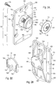
- the plug sleeve 1 of the first variant structured in the in-plane perpendicular flange 10 and this horizontally projecting through sleeve piece 11, so that the front end of the Flanschfrontseite 100 110 of the sleeve piece 11 and the flange back 101, the rear portion 111 of the sleeve piece 11 extends.
- the flange 10 is provided with a plurality of first and second screw holes 104,105 to attach screws 19 .
- the position of the sleeve piece 11 divides the flange 10 into an upper part 102 and an underlying longer lower part 103, with support ribs 106 running on the rear part 111 on the flange rear side 101 .
- the end of the rear part 111 is formed by an annular back surface 118 within which the channel 115 emerges, which has its entrance to the front part 110 .
- a fastened by screws 139 back plate 13 is arranged, which closes the outlet of the channel 115 .
- blind hole threads 119 are provided in the back surface 118 .
- the outer side 130 of the back plate 13 is in principle smooth, on the inner side 131, however, a nose-like protruding second locking contour 134 is present at the bottom center.
- both sides of the locking contour 134 are each a hole 132 for the passage of the screws 139 and a vertical edge web 133 for lateral enclosure an edge zone of the rear part 111 of the sleeve piece 11, lower center a notch 117 in the rear portion 111 extends into the back surface 118 so that in the mounted back plate 13, the second arresting 134 in the notch 117 fits proportionately.
- a direction mark 107 on the flange rear side 101 indicates the prescribed orientation of the receptacle 1 during assembly.
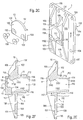
- the front portion 110 of the sleeve piece 11 terminates at the front with a collar 116, which terminates with a ring surface lying in the vertical plane 114 and surrounds a basically circular opening, which forms the entrance of a channel 115 , which changes in geometry through the entire interior of the sleeve piece 11 extends axially.
- a to the back surface 118 protrudes from above a first locking contour 1150 in the channel 115 into it.
- the arresting contour 1150 is preceded by a start 1151 in the manner of an inclined plane.
- the collar 116 merges into an annular shoulder 112 which extends parallel to the annular surface 114 .
- the front part 110 continues in the outer diameter extended to the confluence on the Flanschfrontseite 100 and has a plurality of radially uniformly distributed locking contours 113.
- a cover ring 12 is provided, the disc part 120 comes to rest in the mounted state on the panel front side 500 and its webs 121 engage with their inside locking surface 122 in the latching contours 113 and thereby hold the cover ring 12 in position.
- the straight designed as support arm 2 consists essentially of a round cross-section pipe section, which extends between a male end 20 and a front end 22 .
- the male section 21 On the side of the male end 20 is the male section 21, while the front end 22 is provided with a closure 28 and typically has an upwardly projecting retaining pin 27 , which prevents the sliding down of attached objects, in particular hangers.
- Within the plug portion 21 is in the upper region, with an offset b to the mating end 20, a hole 23, the keyhole-like merges into a hole extension 24 , which expands axially in the direction of the front end 22 .
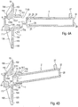
- This sequence of figures illustrates the principle of operation of the existing plug-in sleeve 1 and 2 Tagarm suspension device based on the four characteristic phases when mounting the support arm 2 in the socket 1.
- the removal of a locked in the end position in the socket 1 with its plug portion 21 seated support arm 2 is done in retrograde order ,
- FIG. 4A (first suspension phase)
- the channel 115 of the receptacle 1 with the upper game 1153, the first Arretierkontur 1150 and the upstream start 1151 and the extension 1152 and the second Arretierkontur 134 is initially unoccupied, the entry into the channel 115 so far freely opens into the room. If you intend to introduce a support arm 2 in the receptacle 1 , the support arm 2 to the channel 115 axially aligned and with the mating end 20 facing, be successively approximated.
- the combination of the holes 23,24 above and the groove 25 have to be positioned vertically below.
- FIG. 4B (second hanging phase)
- the plug-in portion 21 is first introduced into the entrance of the channel 115 , wherein the support arm 2 may still be approximately in horizontal alignment or is already looking ahead with its front end 22 is inclined. The inclination is made possible by the upper game 1153 .
- the hole combination 23,24 on the support arm 2 is still completely out of engagement with the first Arresting contour 1150 and their start 1152 in the socket 1, at the same time the groove 25 on the plug portion 21 and the second locking contour 134 of the receptacle 1 are still away from each other.
- a largely still horizontally oriented support arm 2 would meet with the upper portion of its plug portion 21 on the start 1151 and thereby increasingly be moved in tilted position.
- FIG. 4C (third hanging phase)
- the plug portion 21 reaches the maximum possible insertion depth into the channel 115 until the plug end 20 abuts on the inside 131 of the back plate 13 , the second Arretierkontur 134 is retracted into the groove 25 and the first Arretierkontur 1150 with the start 1151 congruent over the hole combination 23,24 stands.
- FIG. 4D (fourth hanging phase)
- the second Arretierkontur 134 passes more completely into the groove 25 and the first Arretierkontur 1150 with the start 1151 drive into the hole combination 23,24 , wherein the upper portion of the plug portion 21 abuts against the ceiling surface in the channel 115 .
- the extension 1152 now forms a quasi-wedge-shaped air gap.
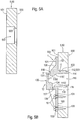
- FIGS. 5A to 5D are identical to FIGS. 5A to 5D
- a panel 50 is used as support structure 5 , which has a through hole 502 first variant for receiving the receptacle 1 , ie near the panel front 500 , the through hole 502 has an annular shoulder 503, before the diameter of the hole 502 is reduced.
- the annular shoulder 112 of the sleeve piece 11 strikes against the annular shoulder 503 , the entire front part 110 being inserted in the through hole 502 .
- the frontal annular surface 114 is in principle at the level of the panel front 500 to lie.
- the flange front 100 is seated on the panel back 501 , wherein the flange 10 is screwed by means of screws 19 through the screw holes 104 and / or 105 with the panel 50 .
- the front part 110 of the sleeve piece 11 with the annular shoulder 112 and the collar 116 is positively and in principle without a gap in the complementarily shaped through hole 502.
- An inserted support arm 2 is encompassed by the annular surface 114 and protrudes freely into the room so that it - in the Function as primary goods carrier - can directly attach goods or support secondary goods carriers, eg trays 3 .
- FIGS. 6A to 6D are identical to FIGS. 6A to 6D
- a panel 50 is used as the support structure 5 , but now for receiving the receptacle 1 has a through hole 502 second variant , which is cylindrical throughout, unchanged in diameter. In the installed state remains before the annular shoulder 112, a collar 116 circumferential, annular gap in the through hole 502, which is visible from the panel front 500 .
- the penetration of a simple through-hole 502 second variant is less expensive than such a first variant.
- the webs 121 engage in the latching contours 113 on the front portion 110 of the sleeve piece 11 .
- the disk part 120 of the cover ring 12 closes the annular gap and is seated on the annular surface 114 and the edge surrounding the mouth of the through-hole 502 on the panel front side 500 .
- the cover ring 12 can be produced as a plastic injection molded part. Visually, an inserted support arm 2 is now surrounded by the cover ring 12 .
- a substructure 51 is used as the support structure 5 for receiving the receptacles 1 , which is constructed, for example, of three vertical supports 510 set up in a plane and in front of a rear background H at systematic intervals.
- a plurality of transverse connectors 518 are inserted between adjacent vertical supports 510 and a plurality of angular brackets 517 serve as a connection between the vertical supports 510 and the background H.
- feet 519 are arranged at the bottom of the vertical supports 510 .
- a vertical support 510 is preferably a hollow square in cross section and has a first forwardly oriented outer surface 511, the adjacent thereto second side outer surface 512, the rearwardly directed third outer surface 513 and the adjacent to the other side directed fourth outer surface 514th Die
- Cross connectors 518 are respectively attached to the second and fourth outer surfaces 512, 544 of adjacent vertical supports 510 .
- the cross connector 518 serve to stabilize the frame structure and ensure compliance with a planned distance between the vertical supports 510.
- the brackets 517 are advantageously mounted on the one hand on the fourth outer surfaces 514 and on the other hand on the background H.
- a plurality of recesses 515 arranged in a grid of, in principle, rectangular blank are provided. These recesses 515 provide access to the internal cavity of the vertical support 510. From the single recess 515 , a plurality of slots extend and, besides, screw holes 516 are provided. In the recesses 515 can insert sleeves 1 , the flange backs 101 come to rest on the first outer surfaces 511 and the rear portions 111 of the sleeve pieces 11 protrude through the recesses 515 in the vertical supports 510 . The support ribs 106 on the flange rear side 101 find their place in the slots extending from the recess 515 .
- the receptacle 1 ' has vorderst designed as a circular flange 10, on the front side 100 of the channel 115 enters. From the flange backside 101 , the entire sleeve piece 11 extends , which is provided with a radially encircling external thread 1110 and has an outer flattening 1111 at the top, the position of which indicates the intended rotational position of the plug-in sleeve 1 ' during assembly. Opposite the flattening 1111 , the sleeve piece 11 is open.
- the sleeve piece 11 closes again with the back surface 118 and internally the same first locking contour 1150 with the start 1151 are present.
- the extension 1152 then follows the flange 10 and then likewise sloping at an angle, and then results in the direction of the back surface 118 through the area open at the bottom on the sleeve piece 11.
- a cap-like union nut 14 is provided which has a bottom 145 and internally an internal thread 144 , the Interaction with the external thread 1110 is determined. Opposite the bottom 145 , the union nut 14 ends with an annular shoulder 143.
- the ring segments 162 of the two sleeves 16 come to lie on the front and back 520, 521 of the vertical plate 52 , while the cylinder segments 163 of the sleeves 16 project into the through hole 522 facing each other.
- the flange 10 is positioned on the front side 520 and the sleeve piece 11 penetrates the through hole 522 and projects beyond the rear side 521.
- the union nut 14 screwed onto the sleeve piece 11 engages the external thread 1110 with its thread 144 and the annular shoulder 143 sits on the ring segment 162 of the adjacent cuff 16 .
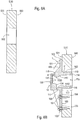
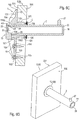
- FIGS. 9A to 9D are identical to FIGS. 9A to 9D.
Landscapes
- Supports Or Holders For Household Use (AREA)
- Display Racks (AREA)
- Pinball Game Machines (AREA)
Claims (11)
- Dispositif de suspension, constitué d'une douille (1, 1') logée dans un trou de passage (502, 515; 522) d'une structure de support (5) et d'un bras de support (2) pouvant être enfoncé dans celle-ci, pouvant être utilisé comme support de produits direct principal ou pour supporter un support de produits secondaire (3,4), dans lequela) la douille (1, 1') présente :aa) une pièce de douille (11) avec une entrée du côté avant dans un canal (115) ;ab) au moins un premier contour de blocage (1150), qui est adjacent au canal (115) ; etac) une bride (10) s'étendant depuis la pièce de douille (11) ;b) le bras de support (2) présente :ba) une partie de fiche (21), qui est destinée à être insérée dans le canal (115), qui se termine au niveau d'une extrémité de fiche (20) et qui présente au moins un premier contour conjugué (23), qui coopère avec le premier contour de blocage (1150) dans la position finale enfoncée du bras de support (2) ; etbb) en face de la partie de fiche (21) se trouve une extrémité avant (22), qui est destinée à s'étendre dans l'espace libre, dans lequelc) le premier contour de blocage (1150) est un rehaussement saillant depuis le dessus à l'intérieur du canal (115), qui est espacé de l'entrée dans le canal (115) ;d) le premier contour conjugué (23) au niveau de la partie de fiche (21) est un trou principal (23) disposé sur le côté supérieur avec un déport (b) par rapport à l'extrémité de fiche (20) ; ete) le canal (115) présente, derrière son entrée dans la partie inférieure, un élargissement (1152) et/ou la partie inférieure de la partie de fiche (21) est réduite en section transversale vers le bas, de telle sorte que la partie de fiche (21) du bras de support (2) enfoncé dans le canal (115) dans la position oblique soulevée, dispose dans cette orientation d'un espace libre avant d'atteindre sa position finale bloquée caractérisé en ce quef) le bras de support (2) présente une section transversale ronde, ovale, rectangulaire ou carrée et est constitué d'un matériau tubulaire.
- Dispositif de suspension selon la revendication 1, caractérisé en ce quea) une admission (1151) est située en amont dans le canal (115) dans la direction de l'entrée par rapport au premier contour de blocage (1150) ; etb) de façon complémentaire à l'admission (1151), un prolongement de contour (24) est situé en amont dans la direction de l'extrémité avant (22) par rapport au premier contour conjugué (23).
- Dispositif de suspension selon la revendication 2, caractérisé en ce quea) l'admission (1151) est formée en principe comme un plan incliné jusqu'au premier contour de blocage (1150) ; etb) le prolongement de contour (24) est conçu comme un élargissement (24) se raccordant au trou principal (23).
- Dispositif de suspension selon au moins l'une des revendications 1 à 3, caractérisé en ce que l'élargissement (1152) est formé dans la douille (1, 1'), au moins en partie à partir d'une paroi pentue de plus en plus oblique dans la profondeur d'emboîtement du canal (115), dans lequel une ouverture de paroi peut être raccordée à la paroi pentue de manière oblique contribuant à l'élargissement (1152).
- Dispositif de suspension selon au moins l'une des revendications 1 à 4, caractérisé en ce que,a) au niveau de la partie de fiche (21) du bras de support (2), en plus du premier contour conjugué (23) se trouve un second contour conjugué (25) ; etb) dans le canal (115), un second contour de blocage (134) complémentaire du second contour conjugué (25), peut être présent.
- Dispositif de suspension selon la revendication 5, caractérisé en ce quea) le second contour conjugué (25) est une rainure (20) débouchant au niveau du côté inférieur de la partie de fiche (21) et au niveau de l'extrémité de fiche (20) ; etb) le second contour de blocage (134) est un rehaussement (134) faisant saillie dans le canal (115).
- Dispositif de suspension selon au moins l'une des revendications 5 et 6, caractérisé en ce quea) le second contour de blocage (134) s'élève depuis le côté interne (131) d'une plaque arrière (13), qui doit être fixer à une surface arrière (118) de la pièce de douille (11) ; etb) une encoche (117) est prévue dans la paroi inférieure de la pièce de douille (11), qui débouche au niveau de la surface arrière (118) et qui fait de la place pour la réception partielle du second contour de blocage (134).
- Dispositif de suspension selon au moins l'une des revendications 1 à 7, caractérisé en ce quea) une bride (10) en forme de plaque s'étend transversalement à travers la pièce de douille (11) ;b) une partie avant (110) de la pièce de douille (11) s'élève en principe verticalement depuis le côté avant de la bride (100) ;c) une partie arrière (111) de la pièce de douille (11) s'élève en principe verticalement depuis le côté arrière de la bride (101) ;d) la bride (10), pour fixation sur la structure de support (5), présente des trous de vis (104, 105) ; ete) la partie avant (110) possède des contours d'encliquetage (113) pour la réception d'une bague de couverture (12), qui sert à recouvrir le bord du trou de passage (502) dans la structure de support (5).
- Dispositif de suspension selon au moins l'une des revendications 1 à 8, caractérisé en ce que la bride (10) peut être utilisée pour :a) être posée, avec son côté avant (100), sur un côté arrière de panneau (501), la partie avant (110) venant reposer dans un trou de passage (502) ; oub) être posée, avec son côté arrière (101), sur une surface avant (511) d'un support (510), la partie arrière (111), à travers un évidement (515), faisant saillie dans l'intérieur du support (510).
- Dispositif de suspension selon au moins l'une des revendications 1 à 7, caractérisé en ce quea) la pièce de douille (11) est munie d'une bride (10), ayant de préférence une forme annulaire, d'un seul tenant et entourant l'entrée dans le canal (115) ;b) la pièce de douille (11) présente un filet externe (1110), qui coopère avec le filet interne (144) d'un écrou-raccord (14) ;c) le côté arrière de la bride (101), dans l'état monté, vient reposer sur le côté avant (520) d'une structure de support (5), de préférence une plaque verticale (52), par exemple, en verre ; etd) l'écrou-raccord (14) est vissé depuis le côté arrière (521) d'une structure de support (5) sur la pièce de douille (11).
- Dispositif de suspension selon la revendication 1, caractérisé en ce que , au niveau de la partie de fiche (21) du bras de support (2), la réduction de l'étendue, dans la zone de section transversale inférieure vers l'extrémité de fiche (20), est axialement uniforme, échelonnée, ou formée en principe en forme de coin.
Applications Claiming Priority (2)
| Application Number | Priority Date | Filing Date | Title |
|---|---|---|---|
| DE202005019809U DE202005019809U1 (de) | 2005-12-19 | 2005-12-19 | Aufhängevorrichtung zur Warenpräsentation |
| PCT/CH2006/000659 WO2007071079A1 (fr) | 2005-12-19 | 2006-11-24 | Dispositif de suspension pour la presentation de produits |
Publications (2)
| Publication Number | Publication Date |
|---|---|
| EP1962648A1 EP1962648A1 (fr) | 2008-09-03 |
| EP1962648B1 true EP1962648B1 (fr) | 2018-03-07 |
Family
ID=36002160
Family Applications (1)
| Application Number | Title | Priority Date | Filing Date |
|---|---|---|---|
| EP06804884.2A Active EP1962648B1 (fr) | 2005-12-19 | 2006-11-24 | Dispositif de suspension pour la presentation de produits |
Country Status (6)
| Country | Link |
|---|---|
| US (1) | US8128043B2 (fr) |
| EP (1) | EP1962648B1 (fr) |
| JP (1) | JP5305920B2 (fr) |
| CN (1) | CN101330852B (fr) |
| DE (1) | DE202005019809U1 (fr) |
| WO (1) | WO2007071079A1 (fr) |
Families Citing this family (27)
| Publication number | Priority date | Publication date | Assignee | Title |
|---|---|---|---|---|
| AU2008232304B2 (en) * | 2007-03-23 | 2013-09-05 | Gesswein, Andreas Klaus | Support arm system |
| US20090173853A1 (en) * | 2008-01-07 | 2009-07-09 | Invue Security Products, Inc. | Universal mounting bracket for merchandise display hooks |
| WO2009154805A1 (fr) * | 2008-06-20 | 2009-12-23 | Hunter Douglas Industries B. V. | Ensembles attache à profil bas, systèmes de montage de panneau et procédés associés |
| DE202009001247U1 (de) * | 2009-02-02 | 2009-04-16 | Visplay International Ag | Vorrichtung zum Aufhängen von Artikeln oder zur Halterung einer Ablage |
| US20110186531A1 (en) * | 2010-02-02 | 2011-08-04 | Nancy Adam | Door and wall suspended caddy for supporting embroidery stabilizer rolls |
| TW201210546A (en) * | 2010-06-25 | 2012-03-16 | Marlite Inc | Merchandise display system |
| DE202010009767U1 (de) | 2010-07-02 | 2010-10-14 | Visplay International Ag | Vorrichtung zur Präsentation von Artikeln |
| WO2012113089A1 (fr) | 2011-02-26 | 2012-08-30 | Visplay International Ag | Dispositif de présentation d'articles |
| US8602227B1 (en) * | 2011-06-08 | 2013-12-10 | Megawall, Inc. | Slatwall panel |
| CA2839317C (fr) * | 2011-07-07 | 2019-01-08 | Andrew Keith Maclaren-Taylor | Systeme de montage |
| US8348210B1 (en) * | 2011-11-29 | 2013-01-08 | Chia-Hung Lee | Positioning device for shelves |
| DE202012008735U1 (de) | 2012-09-12 | 2012-10-18 | Visplay International Ag | Aufhängevorrichtung zur Warenpräsentation mit einem an einer Tragstruktur montierbaren Halter darin einhängbarem Primärträger |
| WO2015031960A1 (fr) * | 2013-09-09 | 2015-03-12 | Lock & Load Shelving Systems Pty Ltd | Système d'étagères flottantes réglables |
| US10119651B2 (en) * | 2015-02-24 | 2018-11-06 | Giorgio Piovan | Upright column stand |
| US9625086B2 (en) * | 2015-04-24 | 2017-04-18 | Michael Chau-Lun CHANG | Fixing device |
| CA2996214A1 (fr) * | 2015-10-23 | 2017-04-27 | The Hillman Group, Inc. | Systeme de stockage mural et composants et procedes associes |
| CN106343832A (zh) * | 2016-10-18 | 2017-01-25 | 芜湖仓实农业装备制造有限公司 | 一种用于旋耕机样机展示的货架 |
| DE102016121435B3 (de) | 2016-11-09 | 2018-03-15 | Juvema Ag | Elektrifiziertes steckhülsenbasiertes Trägersystem |
| FR3060284B1 (fr) * | 2016-12-21 | 2019-07-19 | Hmy Group | Tablette metallique configuree pour equiper un dispositif de presentation d'articles de marchandise, notamment une gondole |
| US11186995B2 (en) * | 2017-09-12 | 2021-11-30 | 9220-6820 Quebec Inc. | Handrail wall mount adapter |
| DE202018103454U1 (de) * | 2018-06-19 | 2018-06-26 | SieMatic Möbelwerke GmbH & Co. KG | Möbelsystem |
| CN110360433B (zh) * | 2019-07-17 | 2024-08-09 | 乐歌人体工学科技股份有限公司 | 显示器支架及其安装方法 |
| US11241106B2 (en) | 2020-03-04 | 2022-02-08 | Qualserv Solutions Llc | System to support cantilevered members from a vertical panel |
| US11559139B2 (en) * | 2020-09-30 | 2023-01-24 | Todd ERVIN | Wine rack apparatus |
| WO2022271643A1 (fr) * | 2021-06-23 | 2022-12-29 | Winehive, Inc. | Système de casier à bouteilles modulaire et composant de casier associé |
| US20240008645A1 (en) * | 2023-04-04 | 2024-01-11 | Robert Bradford | Wall-mounted shelf hanger |
| WO2024258471A1 (fr) * | 2023-06-12 | 2024-12-19 | Sonoco Development, Inc. | Présentoir de point de vente durable comportant des composants pouvant être re-transformés en pâte à papier |
Family Cites Families (17)
| Publication number | Priority date | Publication date | Assignee | Title |
|---|---|---|---|---|
| GB8611689D0 (en) * | 1986-05-13 | 1986-06-18 | Phelps L G | Support system |
| US4770380A (en) * | 1987-06-22 | 1988-09-13 | Ultimate Support Systems, Inc. | Collapsible keyboard stand |
| WO1994002050A1 (fr) * | 1992-07-22 | 1994-02-03 | Crooymans Rene Wilhelm | Systeme de support d'etageres |
| AU693287B2 (en) * | 1994-12-13 | 1998-06-25 | Fehlbaum & Co. | Arrangement of supporting bars for hanging goods to be displayed or for supporting a goods display unit |
| EP0941680A1 (fr) * | 1998-03-13 | 1999-09-15 | Fehlbaum & Co. | Structure d'embase de barre de support pour services commerciaux et institutionnels |
| EP1061837B1 (fr) | 1998-03-13 | 2002-05-08 | Visplay IP AG | Systemes de barres de support pour etablissements de commerce et de service |
| DE29922163U1 (de) * | 1999-12-17 | 2000-02-17 | Fehlbaum & Co., Muttenz | Anordnung zum Aufhängen von Artikeln oder zur Halterung einer Ablage |
| DE20009028U1 (de) | 2000-05-19 | 2000-08-03 | Vitrashop Patente Ag, Muttenz | Tragstangenanordnung |
| ITRN20020003A1 (it) | 2002-01-18 | 2003-07-18 | Mep S P A | Apparato per ancorare rimovibilmente un braccio di supporto ad un relativo elemento di sostegno. |
| DE20202856U1 (de) | 2002-02-22 | 2002-05-23 | Visplay Ip Ag, Muttenz | Steckverbindung mit einem in eine Hülse einsteckbaren Tragarm |
| DE10207715A1 (de) * | 2002-02-23 | 2003-09-04 | Visplay Ip Ag Muttenz | Profilschiene und Zubehör als Aufhängevorrichtung |
| GB0222571D0 (en) | 2002-09-28 | 2002-11-06 | Window Fab & Fixing Supplies | Supporting device |
| DE20318266U1 (de) | 2003-11-26 | 2004-02-19 | Hella Kg Hueck & Co. | Vorrichtung zur Strommessung |
| DE20319266U1 (de) * | 2003-12-11 | 2004-03-11 | Visplay International Ag | Vorrichtung zum Aufhängen von Artikeln oder zur Halterung einer Ablage |
| DE202004004783U1 (de) | 2004-03-26 | 2004-06-09 | Visplay International Ag | Hülse und darin einsteckbarer Arm als Aufhängevorrichtung |
| DE202005002740U1 (de) * | 2005-02-19 | 2005-06-02 | Visplay International Ag | Vorrichtung zum Aufhängen von Artikeln oder zur Halterung einer Ablage und Aufbau damit |
| AU2008232304B2 (en) * | 2007-03-23 | 2013-09-05 | Gesswein, Andreas Klaus | Support arm system |
-
2005
- 2005-12-19 DE DE202005019809U patent/DE202005019809U1/de not_active Expired - Lifetime
-
2006
- 2006-11-24 US US12/086,381 patent/US8128043B2/en not_active Expired - Fee Related
- 2006-11-24 CN CN2006800476596A patent/CN101330852B/zh not_active Expired - Fee Related
- 2006-11-24 WO PCT/CH2006/000659 patent/WO2007071079A1/fr not_active Ceased
- 2006-11-24 JP JP2008544729A patent/JP5305920B2/ja active Active
- 2006-11-24 EP EP06804884.2A patent/EP1962648B1/fr active Active
Also Published As
| Publication number | Publication date |
|---|---|
| JP2009519734A (ja) | 2009-05-21 |
| CN101330852A (zh) | 2008-12-24 |
| WO2007071079A1 (fr) | 2007-06-28 |
| US20090166491A1 (en) | 2009-07-02 |
| US8128043B2 (en) | 2012-03-06 |
| CN101330852B (zh) | 2010-12-08 |
| DE202005019809U1 (de) | 2006-02-16 |
| JP5305920B2 (ja) | 2013-10-02 |
| EP1962648A1 (fr) | 2008-09-03 |
Similar Documents
| Publication | Publication Date | Title |
|---|---|---|
| EP1962648A1 (fr) | Dispositif de suspension pour la presentation de produits | |
| EP1152675B1 (fr) | Ensemble pour la suspension d'articles ou la fixation d'une etagere | |
| DE20314260U1 (de) | Profilschiene und damit erstellte Präsentationsvorrichtung | |
| WO1999016294A2 (fr) | Dispositif de presentation de marchandises | |
| WO1999020094A2 (fr) | Systemes de barres de support pour etablissements de commerce et de service | |
| DE202005002740U1 (de) | Vorrichtung zum Aufhängen von Artikeln oder zur Halterung einer Ablage und Aufbau damit | |
| DE20319266U1 (de) | Vorrichtung zum Aufhängen von Artikeln oder zur Halterung einer Ablage | |
| EP4093242A1 (fr) | Système de structure et rayonnage | |
| EP2544570B1 (fr) | Dispositif de suspension pour la présentation d'objets | |
| EP0716825B1 (fr) | Structure d'embase de crochet horizontal pour la présentation d'articles ou le support d'étagères | |
| EP2219498B1 (fr) | Dispositif de suspension destiné à la présentation d'objets | |
| EP2391244B1 (fr) | Dispositif pour présenter des articles suspendus ou posés à plat | |
| EP1196064A1 (fr) | Dispositif a barre de support | |
| EP2587969B1 (fr) | Dispositif pour présenter des articles | |
| WO2000024981A1 (fr) | Paroi fonctionnelle modulaire | |
| DE29921495U1 (de) | Tragstangenanordnung zum Aufhängen von Artikeln oder zur Halterung einer Ablage | |
| DE19818269A1 (de) | Diagonal-Einstecksystem | |
| EP3461963A1 (fr) | Système porteur et système d'éléments de connexion permettant la connexion des porteurs | |
| DE202005002739U1 (de) | Profil für ein Gestell zur Warenpräsentation und mit dem Profil aufgebautes Gestell | |
| DE202004004783U1 (de) | Hülse und darin einsteckbarer Arm als Aufhängevorrichtung | |
| WO2006086910A1 (fr) | Infrastructure pour bati utilise pour la presentation de marchandises | |
| DE19650815C2 (de) | Utensilienwand | |
| DE29923599U1 (de) | Tragstangenanordnung für Handels- und Dienstleistungseinrichtungen | |
| DE29914330U1 (de) | Gestell zur Präsentation und/oder Lagerung von Gegenständen oder als Raumteiler | |
| DE20301582U1 (de) | Präsentationsvorrichtung für elektronische Geräte |
Legal Events
| Date | Code | Title | Description |
|---|---|---|---|
| PUAI | Public reference made under article 153(3) epc to a published international application that has entered the european phase |
Free format text: ORIGINAL CODE: 0009012 |
|
| 17P | Request for examination filed |
Effective date: 20080601 |
|
| AK | Designated contracting states |
Kind code of ref document: A1 Designated state(s): AT BE BG CH CY CZ DE DK EE ES FI FR GB GR HU IE IS IT LI LT LU LV MC NL PL PT RO SE SI SK TR |
|
| DAX | Request for extension of the european patent (deleted) | ||
| 17Q | First examination report despatched |
Effective date: 20140428 |
|
| GRAP | Despatch of communication of intention to grant a patent |
Free format text: ORIGINAL CODE: EPIDOSNIGR1 |
|
| INTG | Intention to grant announced |
Effective date: 20171027 |
|
| GRAS | Grant fee paid |
Free format text: ORIGINAL CODE: EPIDOSNIGR3 |
|
| GRAA | (expected) grant |
Free format text: ORIGINAL CODE: 0009210 |
|
| AK | Designated contracting states |
Kind code of ref document: B1 Designated state(s): AT BE BG CH CY CZ DE DK EE ES FI FR GB GR HU IE IS IT LI LT LU LV MC NL PL PT RO SE SI SK TR |
|
| REG | Reference to a national code |
Ref country code: GB Ref legal event code: FG4D Free format text: NOT ENGLISH |
|
| REG | Reference to a national code |
Ref country code: CH Ref legal event code: EP Ref country code: AT Ref legal event code: REF Ref document number: 975606 Country of ref document: AT Kind code of ref document: T Effective date: 20180315 |
|
| REG | Reference to a national code |
Ref country code: IE Ref legal event code: FG4D Free format text: LANGUAGE OF EP DOCUMENT: GERMAN |
|
| REG | Reference to a national code |
Ref country code: DE Ref legal event code: R096 Ref document number: 502006015829 Country of ref document: DE |
|
| REG | Reference to a national code |
Ref country code: CH Ref legal event code: NV Representative=s name: LATSCHA SCHOELLHORN PARTNER AG, CH |
|
| REG | Reference to a national code |
Ref country code: NL Ref legal event code: MP Effective date: 20180307 |
|
| REG | Reference to a national code |
Ref country code: LT Ref legal event code: MG4D |
|
| PG25 | Lapsed in a contracting state [announced via postgrant information from national office to epo] |
Ref country code: FI Free format text: LAPSE BECAUSE OF FAILURE TO SUBMIT A TRANSLATION OF THE DESCRIPTION OR TO PAY THE FEE WITHIN THE PRESCRIBED TIME-LIMIT Effective date: 20180307 Ref country code: CY Free format text: LAPSE BECAUSE OF FAILURE TO SUBMIT A TRANSLATION OF THE DESCRIPTION OR TO PAY THE FEE WITHIN THE PRESCRIBED TIME-LIMIT Effective date: 20180307 Ref country code: ES Free format text: LAPSE BECAUSE OF FAILURE TO SUBMIT A TRANSLATION OF THE DESCRIPTION OR TO PAY THE FEE WITHIN THE PRESCRIBED TIME-LIMIT Effective date: 20180307 Ref country code: LT Free format text: LAPSE BECAUSE OF FAILURE TO SUBMIT A TRANSLATION OF THE DESCRIPTION OR TO PAY THE FEE WITHIN THE PRESCRIBED TIME-LIMIT Effective date: 20180307 |
|
| PG25 | Lapsed in a contracting state [announced via postgrant information from national office to epo] |
Ref country code: GR Free format text: LAPSE BECAUSE OF FAILURE TO SUBMIT A TRANSLATION OF THE DESCRIPTION OR TO PAY THE FEE WITHIN THE PRESCRIBED TIME-LIMIT Effective date: 20180608 Ref country code: BG Free format text: LAPSE BECAUSE OF FAILURE TO SUBMIT A TRANSLATION OF THE DESCRIPTION OR TO PAY THE FEE WITHIN THE PRESCRIBED TIME-LIMIT Effective date: 20180607 Ref country code: LV Free format text: LAPSE BECAUSE OF FAILURE TO SUBMIT A TRANSLATION OF THE DESCRIPTION OR TO PAY THE FEE WITHIN THE PRESCRIBED TIME-LIMIT Effective date: 20180307 Ref country code: SE Free format text: LAPSE BECAUSE OF FAILURE TO SUBMIT A TRANSLATION OF THE DESCRIPTION OR TO PAY THE FEE WITHIN THE PRESCRIBED TIME-LIMIT Effective date: 20180307 |
|
| PG25 | Lapsed in a contracting state [announced via postgrant information from national office to epo] |
Ref country code: NL Free format text: LAPSE BECAUSE OF FAILURE TO SUBMIT A TRANSLATION OF THE DESCRIPTION OR TO PAY THE FEE WITHIN THE PRESCRIBED TIME-LIMIT Effective date: 20180307 Ref country code: RO Free format text: LAPSE BECAUSE OF FAILURE TO SUBMIT A TRANSLATION OF THE DESCRIPTION OR TO PAY THE FEE WITHIN THE PRESCRIBED TIME-LIMIT Effective date: 20180307 Ref country code: IT Free format text: LAPSE BECAUSE OF FAILURE TO SUBMIT A TRANSLATION OF THE DESCRIPTION OR TO PAY THE FEE WITHIN THE PRESCRIBED TIME-LIMIT Effective date: 20180307 Ref country code: EE Free format text: LAPSE BECAUSE OF FAILURE TO SUBMIT A TRANSLATION OF THE DESCRIPTION OR TO PAY THE FEE WITHIN THE PRESCRIBED TIME-LIMIT Effective date: 20180307 Ref country code: PL Free format text: LAPSE BECAUSE OF FAILURE TO SUBMIT A TRANSLATION OF THE DESCRIPTION OR TO PAY THE FEE WITHIN THE PRESCRIBED TIME-LIMIT Effective date: 20180307 |
|
| REG | Reference to a national code |
Ref country code: CH Ref legal event code: PCAR Free format text: NEW ADDRESS: GRELLINGERSTRASSE 60, 4052 BASEL (CH) |
|
| PG25 | Lapsed in a contracting state [announced via postgrant information from national office to epo] |
Ref country code: SK Free format text: LAPSE BECAUSE OF FAILURE TO SUBMIT A TRANSLATION OF THE DESCRIPTION OR TO PAY THE FEE WITHIN THE PRESCRIBED TIME-LIMIT Effective date: 20180307 Ref country code: CZ Free format text: LAPSE BECAUSE OF FAILURE TO SUBMIT A TRANSLATION OF THE DESCRIPTION OR TO PAY THE FEE WITHIN THE PRESCRIBED TIME-LIMIT Effective date: 20180307 |
|
| REG | Reference to a national code |
Ref country code: DE Ref legal event code: R097 Ref document number: 502006015829 Country of ref document: DE |
|
| PG25 | Lapsed in a contracting state [announced via postgrant information from national office to epo] |
Ref country code: PT Free format text: LAPSE BECAUSE OF FAILURE TO SUBMIT A TRANSLATION OF THE DESCRIPTION OR TO PAY THE FEE WITHIN THE PRESCRIBED TIME-LIMIT Effective date: 20180709 |
|
| PLBE | No opposition filed within time limit |
Free format text: ORIGINAL CODE: 0009261 |
|
| STAA | Information on the status of an ep patent application or granted ep patent |
Free format text: STATUS: NO OPPOSITION FILED WITHIN TIME LIMIT |
|
| PG25 | Lapsed in a contracting state [announced via postgrant information from national office to epo] |
Ref country code: DK Free format text: LAPSE BECAUSE OF FAILURE TO SUBMIT A TRANSLATION OF THE DESCRIPTION OR TO PAY THE FEE WITHIN THE PRESCRIBED TIME-LIMIT Effective date: 20180307 |
|
| 26N | No opposition filed |
Effective date: 20181210 |
|
| PG25 | Lapsed in a contracting state [announced via postgrant information from national office to epo] |
Ref country code: SI Free format text: LAPSE BECAUSE OF FAILURE TO SUBMIT A TRANSLATION OF THE DESCRIPTION OR TO PAY THE FEE WITHIN THE PRESCRIBED TIME-LIMIT Effective date: 20180307 |
|
| PG25 | Lapsed in a contracting state [announced via postgrant information from national office to epo] |
Ref country code: LU Free format text: LAPSE BECAUSE OF NON-PAYMENT OF DUE FEES Effective date: 20181124 Ref country code: MC Free format text: LAPSE BECAUSE OF FAILURE TO SUBMIT A TRANSLATION OF THE DESCRIPTION OR TO PAY THE FEE WITHIN THE PRESCRIBED TIME-LIMIT Effective date: 20180307 |
|
| REG | Reference to a national code |
Ref country code: BE Ref legal event code: MM Effective date: 20181130 |
|
| REG | Reference to a national code |
Ref country code: IE Ref legal event code: MM4A |
|
| PG25 | Lapsed in a contracting state [announced via postgrant information from national office to epo] |
Ref country code: IE Free format text: LAPSE BECAUSE OF NON-PAYMENT OF DUE FEES Effective date: 20181124 Ref country code: FR Free format text: LAPSE BECAUSE OF NON-PAYMENT OF DUE FEES Effective date: 20181130 |
|
| PG25 | Lapsed in a contracting state [announced via postgrant information from national office to epo] |
Ref country code: BE Free format text: LAPSE BECAUSE OF NON-PAYMENT OF DUE FEES Effective date: 20181130 |
|
| REG | Reference to a national code |
Ref country code: AT Ref legal event code: MM01 Ref document number: 975606 Country of ref document: AT Kind code of ref document: T Effective date: 20181124 |
|
| PG25 | Lapsed in a contracting state [announced via postgrant information from national office to epo] |
Ref country code: AT Free format text: LAPSE BECAUSE OF NON-PAYMENT OF DUE FEES Effective date: 20181124 |
|
| PG25 | Lapsed in a contracting state [announced via postgrant information from national office to epo] |
Ref country code: TR Free format text: LAPSE BECAUSE OF FAILURE TO SUBMIT A TRANSLATION OF THE DESCRIPTION OR TO PAY THE FEE WITHIN THE PRESCRIBED TIME-LIMIT Effective date: 20180307 |
|
| PG25 | Lapsed in a contracting state [announced via postgrant information from national office to epo] |
Ref country code: HU Free format text: LAPSE BECAUSE OF FAILURE TO SUBMIT A TRANSLATION OF THE DESCRIPTION OR TO PAY THE FEE WITHIN THE PRESCRIBED TIME-LIMIT; INVALID AB INITIO Effective date: 20061124 |
|
| PG25 | Lapsed in a contracting state [announced via postgrant information from national office to epo] |
Ref country code: IS Free format text: LAPSE BECAUSE OF FAILURE TO SUBMIT A TRANSLATION OF THE DESCRIPTION OR TO PAY THE FEE WITHIN THE PRESCRIBED TIME-LIMIT Effective date: 20180707 |
|
| REG | Reference to a national code |
Ref country code: DE Ref legal event code: R081 Ref document number: 502006015829 Country of ref document: DE Owner name: VISPLAY GMBH, DE Free format text: FORMER OWNER: VISPLAY INTERNATIONAL AG, MUTTENZ, CH |
|
| REG | Reference to a national code |
Ref country code: GB Ref legal event code: 732E Free format text: REGISTERED BETWEEN 20220113 AND 20220119 |
|
| PGFP | Annual fee paid to national office [announced via postgrant information from national office to epo] |
Ref country code: GB Payment date: 20221122 Year of fee payment: 17 |
|
| PGFP | Annual fee paid to national office [announced via postgrant information from national office to epo] |
Ref country code: CH Payment date: 20231201 Year of fee payment: 18 |
|
| GBPC | Gb: european patent ceased through non-payment of renewal fee |
Effective date: 20231124 |
|
| PG25 | Lapsed in a contracting state [announced via postgrant information from national office to epo] |
Ref country code: GB Free format text: LAPSE BECAUSE OF NON-PAYMENT OF DUE FEES Effective date: 20231124 |
|
| PG25 | Lapsed in a contracting state [announced via postgrant information from national office to epo] |
Ref country code: GB Free format text: LAPSE BECAUSE OF NON-PAYMENT OF DUE FEES Effective date: 20231124 |
|
| REG | Reference to a national code |
Ref country code: CH Ref legal event code: PL |
|
| REG | Reference to a national code |
Ref country code: CH Ref legal event code: PL |
|
| PG25 | Lapsed in a contracting state [announced via postgrant information from national office to epo] |
Ref country code: CH Free format text: LAPSE BECAUSE OF NON-PAYMENT OF DUE FEES Effective date: 20241130 |
|
| PGFP | Annual fee paid to national office [announced via postgrant information from national office to epo] |
Ref country code: DE Payment date: 20251119 Year of fee payment: 20 |