EP1962995B2 - Apparatus for mixing a fluid with a large gas stream, especially for introducing a reducing agent into a flue gas comprising nitrogen oxides - Google Patents
Apparatus for mixing a fluid with a large gas stream, especially for introducing a reducing agent into a flue gas comprising nitrogen oxides Download PDFInfo
- Publication number
- EP1962995B2 EP1962995B2 EP06829637.5A EP06829637A EP1962995B2 EP 1962995 B2 EP1962995 B2 EP 1962995B2 EP 06829637 A EP06829637 A EP 06829637A EP 1962995 B2 EP1962995 B2 EP 1962995B2
- Authority
- EP
- European Patent Office
- Prior art keywords
- flow
- nozzles
- angle
- gas stream
- atomizer
- Prior art date
- Legal status (The legal status is an assumption and is not a legal conclusion. Google has not performed a legal analysis and makes no representation as to the accuracy of the status listed.)
- Active
Links
Images

Classifications
-
- B—PERFORMING OPERATIONS; TRANSPORTING
- B01—PHYSICAL OR CHEMICAL PROCESSES OR APPARATUS IN GENERAL
- B01D—SEPARATION
- B01D53/00—Separation of gases or vapours; Recovering vapours of volatile solvents from gases; Chemical or biological purification of waste gases, e.g. engine exhaust gases, smoke, fumes, flue gases, aerosols
- B01D53/34—Chemical or biological purification of waste gases
- B01D53/74—General processes for purification of waste gases; Apparatus or devices specially adapted therefor
- B01D53/86—Catalytic processes
- B01D53/90—Injecting reactants
-
- B—PERFORMING OPERATIONS; TRANSPORTING
- B01—PHYSICAL OR CHEMICAL PROCESSES OR APPARATUS IN GENERAL
- B01D—SEPARATION
- B01D53/00—Separation of gases or vapours; Recovering vapours of volatile solvents from gases; Chemical or biological purification of waste gases, e.g. engine exhaust gases, smoke, fumes, flue gases, aerosols
- B01D53/34—Chemical or biological purification of waste gases
- B01D53/74—General processes for purification of waste gases; Apparatus or devices specially adapted therefor
- B01D53/77—Liquid phase processes
- B01D53/79—Injecting reactants
-
- B—PERFORMING OPERATIONS; TRANSPORTING
- B01—PHYSICAL OR CHEMICAL PROCESSES OR APPARATUS IN GENERAL
- B01D—SEPARATION
- B01D53/00—Separation of gases or vapours; Recovering vapours of volatile solvents from gases; Chemical or biological purification of waste gases, e.g. engine exhaust gases, smoke, fumes, flue gases, aerosols
- B01D53/34—Chemical or biological purification of waste gases
- B01D53/74—General processes for purification of waste gases; Apparatus or devices specially adapted therefor
- B01D53/86—Catalytic processes
- B01D53/8621—Removing nitrogen compounds
- B01D53/8625—Nitrogen oxides
- B01D53/8631—Processes characterised by a specific device
-
- B—PERFORMING OPERATIONS; TRANSPORTING
- B01—PHYSICAL OR CHEMICAL PROCESSES OR APPARATUS IN GENERAL
- B01F—MIXING, e.g. DISSOLVING, EMULSIFYING OR DISPERSING
- B01F23/00—Mixing according to the phases to be mixed, e.g. dispersing or emulsifying
- B01F23/20—Mixing gases with liquids
- B01F23/21—Mixing gases with liquids by introducing liquids into gaseous media
- B01F23/213—Mixing gases with liquids by introducing liquids into gaseous media by spraying or atomising of the liquids
- B01F23/2132—Mixing gases with liquids by introducing liquids into gaseous media by spraying or atomising of the liquids using nozzles
-
- B—PERFORMING OPERATIONS; TRANSPORTING
- B01—PHYSICAL OR CHEMICAL PROCESSES OR APPARATUS IN GENERAL
- B01F—MIXING, e.g. DISSOLVING, EMULSIFYING OR DISPERSING
- B01F25/00—Flow mixers; Mixers for falling materials, e.g. solid particles
- B01F25/30—Injector mixers
- B01F25/31—Injector mixers in conduits or tubes through which the main component flows
- B01F25/313—Injector mixers in conduits or tubes through which the main component flows wherein additional components are introduced in the centre of the conduit
- B01F25/3131—Injector mixers in conduits or tubes through which the main component flows wherein additional components are introduced in the centre of the conduit with additional mixing means other than injector mixers, e.g. screens, baffles or rotating elements
-
- B—PERFORMING OPERATIONS; TRANSPORTING
- B01—PHYSICAL OR CHEMICAL PROCESSES OR APPARATUS IN GENERAL
- B01F—MIXING, e.g. DISSOLVING, EMULSIFYING OR DISPERSING
- B01F25/00—Flow mixers; Mixers for falling materials, e.g. solid particles
- B01F25/30—Injector mixers
- B01F25/31—Injector mixers in conduits or tubes through which the main component flows
- B01F25/313—Injector mixers in conduits or tubes through which the main component flows wherein additional components are introduced in the centre of the conduit
- B01F25/3132—Injector mixers in conduits or tubes through which the main component flows wherein additional components are introduced in the centre of the conduit by using two or more injector devices
- B01F25/31322—Injector mixers in conduits or tubes through which the main component flows wherein additional components are introduced in the centre of the conduit by using two or more injector devices used simultaneously
-
- B—PERFORMING OPERATIONS; TRANSPORTING
- B01—PHYSICAL OR CHEMICAL PROCESSES OR APPARATUS IN GENERAL
- B01F—MIXING, e.g. DISSOLVING, EMULSIFYING OR DISPERSING
- B01F25/00—Flow mixers; Mixers for falling materials, e.g. solid particles
- B01F25/40—Static mixers
- B01F25/42—Static mixers in which the mixing is affected by moving the components jointly in changing directions, e.g. in tubes provided with baffles or obstructions
- B01F25/43—Mixing tubes, e.g. wherein the material is moved in a radial or partly reversed direction
- B01F25/431—Straight mixing tubes with baffles or obstructions that do not cause substantial pressure drop; Baffles therefor
- B01F25/4316—Straight mixing tubes with baffles or obstructions that do not cause substantial pressure drop; Baffles therefor the baffles being flat pieces of material, e.g. intermeshing, fixed to the wall or fixed on a central rod
-
- F—MECHANICAL ENGINEERING; LIGHTING; HEATING; WEAPONS; BLASTING
- F23—COMBUSTION APPARATUS; COMBUSTION PROCESSES
- F23J—REMOVAL OR TREATMENT OF COMBUSTION PRODUCTS OR COMBUSTION RESIDUES; FLUES
- F23J15/00—Arrangements of devices for treating smoke or fumes
- F23J15/003—Arrangements of devices for treating smoke or fumes for supplying chemicals to fumes, e.g. using injection devices
-
- B—PERFORMING OPERATIONS; TRANSPORTING
- B01—PHYSICAL OR CHEMICAL PROCESSES OR APPARATUS IN GENERAL
- B01D—SEPARATION
- B01D2251/00—Reactants
- B01D2251/20—Reductants
- B01D2251/206—Ammonium compounds
Definitions
- the invention relates to a device for mixing a fluid with a large gas stream flowing in a gas channel (basic flow), in particular for introducing a reducing agent into a flue gas containing nitrogen oxides.
- a device for mixing a fluid with a large gas stream flowing in a gas channel (basic flow) in particular for introducing a reducing agent into a flue gas containing nitrogen oxides.
- Such a device is from the DE 37 23 618 C1 known, wherein the reducing agent is introduced in gas form in the large gas flow rate (flue gas).
- the static mixing element is used to shorten the generally very long mixing paths.
- the mixer element is a rectangular sheet extending across the width of the flue gas channel.
- the nozzle lance with the nozzle is substantially laterally and parallel to the upstream of the edge of the mixer plate relative to the flow direction of the flue gas flow and the nozzle jet of the gaseous reducing agent in the form of the NH3 suspension gas mixture is laterally sprayed onto the back of the mixer element.
- the distribution occurs in the flow vortices immediately at and behind the mixing plate and by the increased turbulence in the flue gas flow downstream of the mixing plate.
- nozzle lances are provided next to each other across the cross-section and a plurality of flow plates associated with the nozzle lances are provided.
- the nozzle must therefore be arranged far enough away from the mixer element that unevaporated droplets can not hit the mixer disk even under the influence of backflows (vortex braids). This leads to an extension of the incorporation-free Rauchgaskanalin required for the intervention. Additional static mixer elements in the flue gas stream after injection can not be used because of the risk of the formation of deposits.
- nozzle lance is connected to a supply of liquid and is equipped with at least two against the flow direction of the gas flow and oppositely inclined spray nozzles, that the atomizer nozzles are associated with a disk-like mixer element and that the atomization guided in such a way that the vaporized gaseous portions contained in the nozzle jet exiting from the atomizer nozzles enter the flow vortices, while the unevaporated droplet-like portions do not enter the flow vortices in the vicinity of the mixer disk due to their inertia and atomization angle.
- the atomizer nozzles are arranged downstream of or upstream from the mixer disk relative to the gas flow rate.
- the mixer disk is circular, elliptical, oval, parabolic, diamond-shaped or triangular, as shown in FIG DE 37 23 618 C1 , Sp.2, Z. 40-45.
- angle between the two atomizer nozzles in the range between 60 ° and 120 °, preferably at 90 °.
- the mixer disk is preferably under one Angle in the range between 30 ° to 90 ° inclined to the flow direction of the gas flow rate.
- the atomizer nozzles are 2-substance nozzles with an atomization auxiliary medium, preferably with compressed air or steam as atomization aid. With 2-fluid nozzles, a fine droplet spectrum can be generated.
- Droplet drop at the nozzle outlet to avoid, the atomizer nozzles can be equipped with barrier or fog air.
- the plane spanned by the nozzle jets of the atomizing nozzles is inclined at an angle in the range of 0 ° to 30 ° to the flow direction of the gas flow rate.
- wake vortices is a natural phenomenon in three-dimensional flows on a body. ( See Prandtl, Oswatitsch, Wieghardt: Leader in fluid mechanics, 9th edition 1990; ISBN 3-528-28209-6, p. 229, Figure 4.41 and related description s).
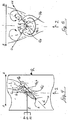
- a circular disc 1 is at an angle ⁇ against that in the Fig.1 From below coming streaming gas flow 2 inclined.
- the gas flow is deflected from its main flow direction and there is an overpressure area.
- the partial flow 2a of the gas flow stream 2 flows at a predetermined angle under the disc.
- a negative pressure area is formed, which is filled by the partial flow 2b of the gas flow rate over the edge of the disc. Due to the flow deflection at the edge of the disk, a horseshoe vortex 3 is formed with the vortex axis 3a shown in dashed lines, which continues in the form of a wake with two symmetrically rotating vortices downstream of the disk.
- the lateral vortices of the horseshoe vortex continue as wake vortices, interfere with the gas flow rate (basic flow) and spread with basic flow.
- the flow state within the wake is highly turbulent.
- the schematically illustrated boundary 3b of horseshoe vortices and vortices must not be understood as a sharp demarcation.
- the position and the structure of the, as well as the opposite directions of rotation of the two vortices can be determined experimentally by means of suitable measuring technology.
- the turbulent mixing of wake vortices and gas flow rate is used to evenly distribute a nearly punctually injected gas flow over a very large cross section.
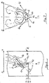
- two atomizing nozzles 4a and 4b are arranged on the head 4c of a nozzle lance 5 extending into a flue gas channel R.
- the atomizer nozzles are arranged on the lee side 1b of the preferably circular mixer disk 1 at a predetermined distance from it.
- the nozzle jet emerging from one of the nozzles 4a and 4b respectively contains gaseous components 6a and non-evaporated droplets 6b.
- the two atomizing nozzles 4a and 4b enclose an angle ⁇ of 120 ° and are inclined against the basic flow. Other angles are possible. The range between 60 ° and 120 ° is preferred.
- the plane spanned by the nozzles 4a and 4b is not inclined against the basic flow.
- the liquid reactant 5a is atomized by means of an atomization auxiliary medium 5c and the nozzle jet 6 is surrounded by barrier or curtain air 5c.
- Fig. 4-7 are schematically shown in addition to the partial flows 2a and 2b, the currents 6a (gaseous component of the jet 6) and 6b (unvaporized droplets) of the injection flow 6.
- the vaporized part 6a of the injection flow follows - as shown in the figures - the curvatures of the basic flow and is rolled into the vortex flow 3.
- the unvaporized droplets 6b follow their inertia below the selected Eindüswinkel ⁇ and thus penetrate on the lee side 1b of the disc 1 to the leeward - leading back vortex, so that a deposit formation of droplets and particulate matter from the flue gas is substantially avoided.
- the droplets of the partial stream 6b later evaporate in the outgas stream and are sufficiently mixed in by the turbulences present there.
- the partial stream 6a may also contain ultrafine droplets, but evaporate quickly and therefore contribute little to the formation of fouling, if at all. Based on the amount of reducing agent, the partial stream 6a contains substantially more reducing agent than the partial stream 6b. In the case of non-inventive penetration of the vortex pebbles, however, the smaller partial flow 6b would lead to considerable deposit formation.
- the nozzle head with the atomizer nozzles 4a and 4b upstream of the mixer disk 1 is arranged.
- the atomizer nozzles 4a and 4b are arranged so that the axes of the nozzle jets 6 extend on both sides at a sufficient distance next to the mixer disk 1.
- the distance to the disc may preferably be about 0.5 m.
- the droplet trajectories 6b penetrate the mixer disk to directed vortices.
- a plurality of mixer disks with associated atomizer nozzles can be provided distributed over the channel cross-section.
Landscapes
- Chemical & Material Sciences (AREA)
- Engineering & Computer Science (AREA)
- Chemical Kinetics & Catalysis (AREA)
- Environmental & Geological Engineering (AREA)
- General Chemical & Material Sciences (AREA)
- Biomedical Technology (AREA)
- Health & Medical Sciences (AREA)
- Analytical Chemistry (AREA)
- Oil, Petroleum & Natural Gas (AREA)
- Mechanical Engineering (AREA)
- General Engineering & Computer Science (AREA)
- Dispersion Chemistry (AREA)
- Treating Waste Gases (AREA)
- Nozzles (AREA)
- Chimneys And Flues (AREA)
- Gas Separation By Absorption (AREA)
Abstract
Description
Die Erfindung betrifft eine Vorrichtung zum Vermischen eines Fluids mit einem in einem Gaskanal strömenden großen Gasmengenstrom (Grundströmung), insbesondere zum Einbringen eines Reduktionsmittels in ein Stickoxide enthaltendes Rauchgas,
mit mindestens einer Düsenlanze mit mindestens einer Düse für die Zuführung des Fluids, deren Achse mit der Strömungsrichtung des Gasmengenstroms einen Winkel bildet, und mindestens einem der Düse mit Abstand zugeordneten flächigen Mischerelement, das mit der Strömungsrichtung des Gasmengenstroms einen Winkel bildet, wobei sich an dem Mischerelement Strömungswirbel ausbilden und zumindest ein Teil des Fluids in diese Strömungswirbel gelangt.The invention relates to a device for mixing a fluid with a large gas stream flowing in a gas channel (basic flow), in particular for introducing a reducing agent into a flue gas containing nitrogen oxides.
with at least one nozzle lance with at least one nozzle for the supply of the fluid, the axis of which forms an angle with the flow direction of the gas flow, and at least one of the nozzle at a distance associated planar mixer element which forms an angle with the flow direction of the gas flow rate, wherein on the Mixing element flow vortex form and at least a portion of the fluid passes into these flow vortex.
Eine solche Vorrichtung ist aus der
Bei SCR-Anlagen zur Entstickung (Selektive Catalytische Reduktion) von Rauchgasen z.B. von Kraftwerksfeuerungen mittels Reduktionsmittel und Katalysator ist es üblich, dass im Fall von NH3 als Reduktionsmittel dieses in Form von druckverflüssigtem NH3 oder von Ammoniakwasser (NH4OH) gelagert und vorverdampftes NH3 mit einem Traggasstrom in den Rauchgasstrom eingedüst und mit diesem vermischt wird. Im Fall von Harnstoff als Reduktionsmittel wird zunächst eine wässrige Harnstofflösung erzeugt, die nach geeigneter Aufarbeitung dann ebenfalls gasförmig in den Rauchgasstrom eingedüst wird.In SCR plants for denitrification (selective catalytic reduction) of flue gases, e.g. From power plant firing means of reducing agent and catalyst, it is customary that in the case of NH3 as a reducing agent stored in the form of pressure liquefied NH3 or ammonia (NH4OH) and pre-evaporated NH3 is injected with a Traggasstrom in the flue gas stream and mixed with this. In the case of urea as a reducing agent, an aqueous urea solution is first produced, which is then likewise injected in gaseous form into the flue gas stream after suitable workup.
Bei der bekannten Vorrichtung ist das Mischerelement ein sich über die Breite des Rauchgaskanals erstreckendes rechteckiges Blech. Die Düsenlanze mit der Düse liegt im wesentlichen seitlich und parallel zu der bezogen auf die Strömungsrichtung des Rauchgasstroms stromauf liegenden Kante des Mischerblechs und der Düsenstrahl des gasförmigen Reduktionsmittels in Form des NH3-Traggas-Gemisches wird seitlich auf die Rückseite des Mischerelements gedüst. Die Verteilung erfolgt in den Strömungswirbeln unmittelbar an und hinter dem Mischblech und durch die erhöhte Turbulenz in der Rauchgasströmung stromab des Mischblechs. Bei einem großen Kanalquerschnitt sind querschnittsfüllend nebeneinander Düsenlanzen, sowie mehrere den Düsenlanzen zugeordnete Strömungsbleche vorgesehen.In the known device, the mixer element is a rectangular sheet extending across the width of the flue gas channel. The nozzle lance with the nozzle is substantially laterally and parallel to the upstream of the edge of the mixer plate relative to the flow direction of the flue gas flow and the nozzle jet of the gaseous reducing agent in the form of the NH3 suspension gas mixture is laterally sprayed onto the back of the mixer element. The distribution occurs in the flow vortices immediately at and behind the mixing plate and by the increased turbulence in the flue gas flow downstream of the mixing plate. In the case of a large channel cross-section, nozzle lances are provided next to each other across the cross-section and a plurality of flow plates associated with the nozzle lances are provided.
Es ist auch eine Eindüsung von Ammoniakwasser (flüssiges NH40H) oder Harnstofflösung ohne Vorverdampfung direkt in den Rauchgasstrom auf der Rückseite eines Mischerelements vorgeschlagen worden, wobei die Düse so auf der Rückseite (Lee-Seite) des Mischelements angeordnet ist, dass die Eindüsrichtung parallel zum Gasmengenstrom des Rauchgases verläuft. Der Düsenstrahl besteht aus einem Gemisch von Gas und Flüssigkeitströpfchen, die in der ca. 300°C warmen Umgebung nach einer gewissen Zeit verdampft sind. Dabei besteht die Gefahr, dass Reduktionsmitteltröpfchen zusammen mit in den Rauchgasen enthaltenen Staubteilchen zur betonartigen Belagbildung auf dem oder den eingesetzten Mischerelementen, Tragelementen für das Mischerelement und gegebenenfalls auf den Rauchgaskanalwänden führen. Die Düse muß daher soweit von dem Mischerelement entfernt angeordnet sein, dass nicht verdampfte Tröpfchen auch unter dem Einfluß von Rückströmungen (Wirbelzöpfen) nicht auf die Mischerscheibe treffen können. Dies führt zu einer Verlängerung der für die Einmischung erforderlichen einbautenfreien Rauchgaskanallänge. Zusätzliche statische Mischerelemente im Rauchgasstrom nach der Eindüsung können wegen der Gefahr der Belagbildung nicht eingesetzt werden.It has also been proposed an injection of ammonia water (liquid NH40H) or urea solution without pre-evaporation directly into the flue gas stream on the back of a mixer element, wherein the nozzle is arranged on the back (Lee side) of the mixing element, that the injection direction parallel to the gas flow rate the flue gas runs. The jet consists of a mixture of gas and liquid droplets, which are evaporated in the approximately 300 ° C warm environment after a certain time. There is a risk that reducing agent droplets together with dust particles contained in the flue gases lead to concrete-like deposit formation on the mixer element (s) used, support elements for the mixer element and optionally on the flue gas duct walls. The nozzle must therefore be arranged far enough away from the mixer element that unevaporated droplets can not hit the mixer disk even under the influence of backflows (vortex braids). This leads to an extension of the incorporation-free Rauchgaskanallänge required for the intervention. Additional static mixer elements in the flue gas stream after injection can not be used because of the risk of the formation of deposits.
Es ist die Aufgabe der Erfindung, die gattungsgemäße Vorrichtung derart zu verbessern, dass bei direkter Eindüsung einer Flüssigkeit als Fluid, insbesondere flüssigem Reduktionsmittel, bei kurzem Mischweg eine Belagbildung in wesentlichem Umfang vermieden wird.It is the object of the invention to improve the generic device such that in direct injection of a liquid as a fluid, in particular liquid reducing agent, with a short mixing path a deposit formation is avoided to a significant extent.
Diese Aufgabe wird bei einer gattungsgemäßen Vorrichtung dadurch gelöst, dass die Düsenlanze mit einer Zuführung von Flüssigkeit verbunden ist und mit mindestens zwei gegen die Strömungsrichtung des Gasmengenstroms und gegensinnig zueinander geneigten Zerstäuberdüsen bestückt ist, dass die Zerstäuberdüsen einem scheibenartig ausgebildeten Mischerelement zugeordnet sind und dass die Zerstäubung derart geführt ist, dass die in dem aus den Zerstäuberdüsen jeweils austretenden Düsenstrahl enthaltenen verdampften gasförmigen Anteile in die Strömungswirbel eintreten , während die nicht verdampften tröpfchenförmigen Anteile aufgrund ihrer Trägheit und des Zerstäuberwinkels nicht in die Strömungswirbel in der Nähe der Mischerscheibe eintreten.This object is achieved in a generic device in that the nozzle lance is connected to a supply of liquid and is equipped with at least two against the flow direction of the gas flow and oppositely inclined spray nozzles, that the atomizer nozzles are associated with a disk-like mixer element and that the atomization guided in such a way that the vaporized gaseous portions contained in the nozzle jet exiting from the atomizer nozzles enter the flow vortices, while the unevaporated droplet-like portions do not enter the flow vortices in the vicinity of the mixer disk due to their inertia and atomization angle.
Die Zerstäuberdüsen sind bezogen auf den Gasmengenstrom stromab oder stromauf der Mischerscheibe angeordnet.The atomizer nozzles are arranged downstream of or upstream from the mixer disk relative to the gas flow rate.
Bei beiden Ausführungsformen wird sichergestellt, daß große, unverdampfte Tropfen aufgrund ihrer Trägheit weitgehend der ursprünglichen Strahlachse folgen und nicht auf die Mischerscheibe treffen und dort zur Belagbildung führen könnten, während das im heißen Rauchgas verdampfte NH3 aus dem zugeführten flüssigen Reduktionsmittel der Rauchgasströmung folgt und als Gas in die sich unmittelbar hinter der Mischerscheibe aufrollenden Wirbelschleppen eingebunden wird. Auf diese Weise wird auch bei der Direkteindüsung von NH40H eine Vorverteilung erreicht.In both embodiments, it is ensured that large, non-evaporated droplets due to their inertia largely follow the original beam axis and could not hit the mixer disk and lead there to deposit formation, while the vaporized in the hot flue gas NH3 from the supplied liquid reducing agent of the flue gas flow follows and as gas into which wake vortex is rolled up directly behind the mixer disk. In this way, a pre-distribution is achieved even with the direct injection of NH40H.
Vorzugsweise ist die Mischerscheibe kreisförmig, elliptisch, oval, parabelförmig, rautenförmig oder dreieckförmig ausgebildet, wie dies aus der
Es ist zweckmäßig, wenn der Winkel zwischen den beiden Zerstäuberdüsen im Bereich zwischen 60° und 120°, vorzugsweise bei 90°, liegt.It is useful if the angle between the two atomizer nozzles in the range between 60 ° and 120 °, preferably at 90 °.
Die Mischerscheibe ist vorzugsweise unter einem Winkel im Bereich zwischen 30° bis 90° zur Strömungsrichtung des Gasmengenstroms geneigt.The mixer disk is preferably under one Angle in the range between 30 ° to 90 ° inclined to the flow direction of the gas flow rate.
Es ist zweckmäßig, wenn die Zerstäuberdüsen 2-Stoff-Düsen mit einem Zerstäubungshilfsmedium sind, vorzugsweise mit Druckluft oder Wasserdampf als Zerstäubungshilfsmittel. Mit 2-Stoff-Düsen kann ein feines Tröpfchenspektrum erzeugt werden.It is expedient if the atomizer nozzles are 2-substance nozzles with an atomization auxiliary medium, preferably with compressed air or steam as atomization aid. With 2-fluid nozzles, a fine droplet spectrum can be generated.
Es können aber auch Druckdüsen ohne Hilfsmedium als Zerstäuberdüsen eingesetzt werden.However, it is also possible to use pressure nozzles without auxiliary medium as atomizing nozzles.
Um einen. Tröpchenfall am Düsenaustritt zu vermeiden, können die Zerstäuberdüsen mit Sperr- bzw. Schleierluft ausgerüstet sein.To one. Droplet drop at the nozzle outlet to avoid, the atomizer nozzles can be equipped with barrier or fog air.
Um die Tröpfchentrajektorien noch in ihrer Ausrichtung zu optimieren, ist die von den Düsenstrahlen der Zerstäuberdüsen aufgespannte Ebene unter einem Winkel im Bereich von 0° bis 30° gegen die Strömungsrichtung des Gasmengenstroms geneigt.In order to optimize the droplet trajectories nor in their orientation, the plane spanned by the nozzle jets of the atomizing nozzles is inclined at an angle in the range of 0 ° to 30 ° to the flow direction of the gas flow rate.
Die Erfindung wird nachstehend beispielsweise anhand der Figuren näher erläutert. Es zeigt:
- Fig.1
- eine dreidimensionale Darstellung eines sich an einer von einem Gasmengenstrom angeströmten und gegen den Strom unter einem Winkel α geneigten kreisförmigen Scheibe einstellenden Hufeisenwirbels mit Wirbelschleppe,
- Fig.2
- eine Seitenansicht quer zur Linie A - A gemäß
Fig. 1 , - Fig.3
- eine Vorderansicht mit Blick auf die Lee-Seite der Scheibe quer zur Linie B - B in der Darstellung gemäß
Fig. 1 , - Fig.4
- eine Seitenansicht vergleichbar
Fig.2 bei einer erster Ausführungsform der erfindungsgemäßen Vorrichtung, bei der die Zerstäuberdüsen bezogen auf Gasmengenstrom stromab der Mischerscheibe angeordnet sind, wobei der Querschnitt des den Gasmengenstrom führenden Gaskanals mit dargestellt ist - Fig.5
- eine Rückansicht mit Blick auf die Luv-Seite der Scheibe quer zur Linie B - B in der Darstellung gemäß
Fig. 1 , - Fig.6
- eine Seitenansicht vergleichbar
Fig.4 bei einer zweiten Ausführungsform der erfindungsgemäßen Vorrichtung, bei der die Zerstäuberdüsen bezogen auf Gasmengenstrom stromauf der Mischerscheibe angeordnet sind, und - Fig.7
- eine Vorderansicht mit Blick auf die Lee-Seite der Scheibe quer zur Linie B - B in der Darstellung gemäß
Fig. 1 .
- Fig.1
- a three-dimensional representation of a horseshoe vortex with wake turbulence, which flows against a circular disk and flows against the flow at an angle .alpha.
- Fig.2
- a side view transverse to the line A - A according to
Fig. 1 . - Figure 3
- a front view looking at the lee side of the disc transverse to the line B - B in the illustration according to
Fig. 1 . - Figure 4
- a side view similar
Fig.2 in a first embodiment of the device according to the invention, in which the atomizer nozzles are arranged downstream of the mixer disk relative to the gas flow rate, wherein the cross section of the gas flow channel leading to the gas flow is also shown - Figure 5
- a rear view overlooking the windward side of the disc transverse to the line B - B in the illustration according to
Fig. 1 . - Figure 6
- a side view similar
Figure 4 in a second embodiment of the device according to the invention, in which the atomizer nozzles are arranged upstream of the mixer disk relative to the gas flow rate, and - Figure 7
- a front view looking at the lee side of the disc transverse to the line B - B in the illustration according to
Fig. 1 ,
Bei der Ausbildung von Wirbelschleppen handelt es um ein natürliches Phänomen in dreidimensionalen Strömungen an einem Körper. (
Die Entstehung, die Form und Lage solcher Wirbelschleppen im Abstrom von Mischerscheiben sollen zunächst in den
Eine kreisförmige Scheibe 1 ist im Winkel α gegen den in der
Bei anderen Scheibenformen wie Ellipsenform, Ovalform, Parabelform, Rautenform oder Dreiecksform bilden sich vergleichbare Wirbel mit Wirbelschleppen aus.In other disc shapes such as ellipse shape, oval shape, parabolic shape, diamond shape or triangular shape form comparable vortex vortex wakes.
Die turbulente Durchmischung von Wirbelschleppen und Gasmengenstrom wird genutzt, um einen nahezu punktuell eingedüsten Gasstrom gleichmäßig über einen sehr großen Querschnitt zu verteilen.The turbulent mixing of wake vortices and gas flow rate is used to evenly distribute a nearly punctually injected gas flow over a very large cross section.
Bei der Ausführungsform der erfindungsgemäßen Vorrichtung gemäß
Die von den Düsen 4a und 4b aufgespannte Ebene ist nicht gegen die Grundströmung geneigt.The plane spanned by the
In den
In den
Die Tröpfchen des Teilstroms 6b verdampfen später im Rausgasstrom und werden durch die dort vorhandenen Turbulenzen in ausreichendem Maße eingemischt.The droplets of the partial stream 6b later evaporate in the outgas stream and are sufficiently mixed in by the turbulences present there.
Der Teilstrom 6a kann auch noch Feinstströpfchen enthalten, die aber schnell verdampfen und daher zur Belagbildung - wenn überhaupt - nur wenig beitragen. Bezogen auf die Menge an Reduktionsmittel enthält der Teilstrom 6a wesentlich mehr an Reduktionsmittel als der Teilstrom 6b. Bei nicht erfindungsgemäßem Durchdringen der Wirbelzöpfe würde der geringere Teilstrom 6b aber zu einer erheblichen Belagbildung führen.The partial stream 6a may also contain ultrafine droplets, but evaporate quickly and therefore contribute little to the formation of fouling, if at all. Based on the amount of reducing agent, the partial stream 6a contains substantially more reducing agent than the partial stream 6b. In the case of non-inventive penetration of the vortex pebbles, however, the smaller partial flow 6b would lead to considerable deposit formation.
Bei der Ausführungsform gemäß den
Bei der Ausführungsform gemäß den
Bei dieser Ausführungsform und bei der Ausführungsform gemäß
Bei der Ausführungsform gemäß
Es ist selbstverständlich, dass bei großen Kanalquerschnitten mehrere Mischerscheiben mit zugeordneten Zerstäuberdüsen über den Kanalquerschnitt verteilt vorgesehen seien können. Es können auch mehr als zwei Düsen z.B. in Igelanordnung einer Mischerscheibe zugeordnet sein. Sie müssen nur so angeordnet sein, dass die Tröpchentrajekorien die Wirbel durchdringen.It is self-evident that, with large channel cross-sections, a plurality of mixer disks with associated atomizer nozzles can be provided distributed over the channel cross-section. There may also be more than two nozzles e.g. be assigned in hedgehog arrangement of a mixer disk. They just need to be arranged so that the droplet trajectories penetrate the vertebrae.
- 11
- Scheibe (Mischerscheibe)Disc (mixer disc)
- 1a1a
- Luv - Seite der ScheibeLuv - side of the disc
- 1b1b
- Lee - Seite der ScheibeLee - side of the disc
- 22
- GasmengenstromGas flow rate
- 2a2a
- Gasmengenstrom, Teilstrom auf der Luv-Seite 1a der ScheibeGas flow, partial flow on the windward side 1a of the disk
- 2b2 B
- Gasmengenstrom, Teilstrom zur Lee-Seite 1bder ScheibeGas flow, partial flow to the lee side 1b of the disc
- 33
- Hufeisenwirbel und WirbelschleppeHorseshoe vortices and wake vortices
- 3a3a
- Wirbelachsevortex axis
- 3b3b
- Außengrenze des WirbelsExternal border of the vortex
- 44
- Düsenlanzenozzle lance
- 4a4a
- Zerstäuberdüseatomizer
- 4b4b
- Zerstäuberdüseatomizer
- 4c4c
- Düsenkopfnozzle head
- 5a5a
- Zuführung von flüssigem ReduktionsmittelSupply of liquid reducing agent
- 5b5b
- Zuführung von gasförmigen ZerstäuberhilfsmediumSupply of gaseous atomizer auxiliary medium
- 5c5c
- Zuführung von Sperrluft bzw. SchleierluftSupply of sealing air or fog air
- 66
- Düsenstrahljet
- 6a6a
- gasförmiger Anteilgaseous portion
- 6b6b
- unverdampfte Tröpfchenunvaporized droplets
- RR
- RauchgaskanalFlue
Claims (9)
- Apparatus for mixing a fluid with a large gas stream flowing in a gas duct, having at least one metering lance with at least one nozzle for supplying the fluid, the axis of which forms an angle with the direction of flow of the gas stream, and
at least one flat mixer element associated with and spaced from the at least one nozzle, which forms an angle with the direction of flow of the gas stream,
whereby flow eddies form in the gas stream at the mixer element and at least a portion of the fluid enters into these flow eddies, characterized,in that the metering lance (5) is connected to a liquid supply (5a) and is provided with at least two atomizer nozzles (4a 4b), which are inclined relative to the direction of flow of the gas stream (2) and are inclined in opposite directions relative to one another to form an atomizer angle (β),in that the atomizer nozzles (4a, 4b), relative to the gas stream (2), are disposed downstream on the lee side (1b) or upstream on the windward side (1a) of the disc-like mixer element (1) and in that and the atomization is effected in such a way that the vaporized gaseous portions (6a) contained in the nozzle stream (6) respectively exiting the atomizer nozzles enter the flow eddies (3; 3a; 3b), while the non-vaporized dropletlike portions (6b) due to their inertia and the atomizer angle (β) do not enter the flow eddies (3; 3a; 3b) in the vicinity of the mixer disk (1). - Apparatus according to Claim 1,
characterized
in that the mixer disk (1) has a circular, elliptical, oval, parabola, diamond, triangular shape. - Apparatus according to Claims 1 to 2,
characterized
in that the angle (β) between the two atomizer nozzles is in the range of between 60° and 120°. - Apparatus according to one of the Claims 1 to 3,
characterized
in that the mixer disk (1) is inclined to the direction of flow of the gas stream at an angle (α) in the range of between 30° to 90°. - Apparatus according to one of the Claims 1 to 4,
characterized
in that the atomizer nozzles (4a, 4b) are 2-material nozzles having auxiliary atomization medium (5b). - Apparatus according to one of the Claims 1 to 5,
characterized
in that the atomizer nozzles (4a, 4b) are pressure nozzles. - Apparatus according to one of the Claims 1 to 6,
characterized
in that the atomizer nozzles (4a, 4b) are provided with blocking or screening air (5c). - Apparatus according to one of the Claims 1 to 7,
characterized
in that the plane defined by the nozzle streams of the atomizer nozzles is inclined to the direction of flow of the gas stream (2) at an angle (γ) in the range of from 0° to 30°. - Apparatus according to one of the Claims 1 to 8,
characterized
in that the atomizer angle (β) is 90°.
Priority Applications (1)
| Application Number | Priority Date | Filing Date | Title |
|---|---|---|---|
| PL06829637T PL1962995T5 (en) | 2005-12-15 | 2006-12-14 | Apparatus for mixing a fluid with a large gas stream, especially for introducing a reducing agent into a flue gas comprising nitrogen oxides |
Applications Claiming Priority (2)
| Application Number | Priority Date | Filing Date | Title |
|---|---|---|---|
| DE102005059971A DE102005059971A1 (en) | 2005-12-15 | 2005-12-15 | Smoke gases at high flow-rates are treated, to destroy nitrogen oxides, by injection of liquid reducing agents with high efficiency dispersal by vortex shedding from an inclined planar baffle |
| PCT/EP2006/012087 WO2007073881A1 (en) | 2005-12-15 | 2006-12-14 | Apparatus for mixing a fluid with a large gas stream, especially for introducing a reducing agent into a flue gas comprising nitrogen oxides |
Publications (3)
| Publication Number | Publication Date |
|---|---|
| EP1962995A1 EP1962995A1 (en) | 2008-09-03 |
| EP1962995B1 EP1962995B1 (en) | 2009-11-18 |
| EP1962995B2 true EP1962995B2 (en) | 2017-09-06 |
Family
ID=37859543
Family Applications (1)
| Application Number | Title | Priority Date | Filing Date |
|---|---|---|---|
| EP06829637.5A Active EP1962995B2 (en) | 2005-12-15 | 2006-12-14 | Apparatus for mixing a fluid with a large gas stream, especially for introducing a reducing agent into a flue gas comprising nitrogen oxides |
Country Status (10)
| Country | Link |
|---|---|
| US (1) | US8033531B2 (en) |
| EP (1) | EP1962995B2 (en) |
| CN (1) | CN101336130B (en) |
| AT (1) | ATE448868T1 (en) |
| DE (2) | DE102005059971A1 (en) |
| ES (1) | ES2337089T5 (en) |
| PL (1) | PL1962995T5 (en) |
| RU (1) | RU2389537C2 (en) |
| UA (1) | UA95937C2 (en) |
| WO (1) | WO2007073881A1 (en) |
Families Citing this family (13)
| Publication number | Priority date | Publication date | Assignee | Title |
|---|---|---|---|---|
| DE102008028625B4 (en) * | 2008-04-21 | 2011-12-15 | Tenneco Gmbh | Method for mixing an exhaust gas stream |
| US9095827B2 (en) | 2008-04-21 | 2015-08-04 | Tenneco Automotive Operating Company Inc. | Exhaust gas flow mixer |
| US8939638B2 (en) | 2008-04-21 | 2015-01-27 | Tenneco Automotive Operating Company Inc. | Method for mixing an exhaust gas flow |
| US8272777B2 (en) | 2008-04-21 | 2012-09-25 | Heinrich Gillet Gmbh (Tenneco) | Method for mixing an exhaust gas flow |
| CN101601965B (en) * | 2009-07-24 | 2011-12-28 | 华电环保系统工程有限公司 | Ammonia-spraying grid device for SCR-method flue gas denitrification, and SCR-method flue gas denitrification process |
| WO2014025538A1 (en) | 2012-08-10 | 2014-02-13 | Tenneco Automotive Operating Company Inc. | Method for mixing an exhaust gas flow |
| DE102013109317A1 (en) | 2013-08-07 | 2015-02-12 | Radwan Matrmawi | Device for the chemical and energetic utilization of flue gas |
| DE112014005413B4 (en) * | 2013-11-26 | 2019-08-29 | Tenneco Automotive Operating Company Inc. | Exhaust flow mixer |
| US9664082B2 (en) | 2014-06-02 | 2017-05-30 | Caterpillar Inc. | Reductant dosing system having staggered injectors |
| US9534525B2 (en) | 2015-05-27 | 2017-01-03 | Tenneco Automotive Operating Company Inc. | Mixer assembly for exhaust aftertreatment system |
| RU2633671C1 (en) * | 2016-05-24 | 2017-10-16 | Андрей Юрьевич Беляев | Mixer-turbulator |
| WO2019200360A1 (en) | 2018-04-12 | 2019-10-17 | Resource West, Inc. | Evaporator for ambient water bodies, and related system and method |
| DE102018005192B3 (en) | 2018-07-02 | 2019-12-05 | Truma Gerätetechnik GmbH & Co. KG | burner device |
Citations (3)
| Publication number | Priority date | Publication date | Assignee | Title |
|---|---|---|---|---|
| DD269101A1 (en) † | 1987-09-30 | 1989-06-21 | Orgreb Inst Kraftwerke | DEVICE FOR THE INTENSE MIXING OF SMOKE GASES WITH ADDITIVES PROVIDED IN THE EQUIVALENT |
| EP0956897A2 (en) † | 1998-05-11 | 1999-11-17 | Deutsche Babcock Anlagen Gmbh | Apparatus for mixing a gas flowing through a conduit |
| EP1166861A1 (en) † | 2000-06-19 | 2002-01-02 | Balcke-Dürr Energietechnik GmbH | Mixer for mixing at least two gas streams or other Newtonian liquids |
Family Cites Families (23)
| Publication number | Priority date | Publication date | Assignee | Title |
|---|---|---|---|---|
| DE1071604B (en) | 1959-12-17 | |||
| US34586A (en) * | 1862-03-04 | Improvement in setting artificial teeth | ||
| DE434908C (en) | 1925-02-01 | 1926-10-05 | Abt Hoerder Ver | Procedure for laying pipe strings |
| US2937013A (en) * | 1956-04-20 | 1960-05-17 | Ernest F Fisher | Water cooled deflectors used in fly ash suppression systems |
| NL151263B (en) | 1966-06-22 | 1976-11-15 | Shell Int Research | TUBE-SHAPED LIQUID GAS CONTACT DEVICE. |
| FR1530772A (en) * | 1966-06-22 | 1968-06-28 | Shell Int Research | Apparatus for intimate contact of liquids and vapors |
| US3317197A (en) * | 1966-06-22 | 1967-05-02 | Chemical Construction Corp | Stack mounted scrubber |
| US4744958A (en) * | 1972-05-12 | 1988-05-17 | Pircon Ladislav J | Heterogeneous reactor |
| US3957465A (en) * | 1972-05-12 | 1976-05-18 | Pircon Ladislav J | Pollution control apparatus and method |
| US3958961A (en) * | 1973-02-02 | 1976-05-25 | United States Filter Corporation | Wet electrostatic precipitators |
| US4358433A (en) * | 1976-04-16 | 1982-11-09 | Pircon Ladislav J | Heterogeneous process |
| US4070424A (en) * | 1976-09-21 | 1978-01-24 | Uop Inc. | Method and apparatus for conditioning flue gas with a mist of H2 SO4 |
| DE3043239C2 (en) * | 1980-11-15 | 1985-11-28 | Balcke-Dürr AG, 4030 Ratingen | Method and device for mixing at least two fluid partial flows |
| GB8710685D0 (en) * | 1987-05-06 | 1987-06-10 | Turbotak Inc | Cluster nozzles |
| DE3723618C1 (en) * | 1987-07-17 | 1988-12-01 | Steinmueller Gmbh L & C | Apparatus for mixing two gases |
| DD277215A1 (en) | 1988-11-23 | 1990-03-28 | Orgreb Inst Kraftwerke | DEVICE FOR PREVENTING ADDITIVE ATTACHMENTS TO A PNEUMATICALLY OPERATED TWO-STAGE DEVICE SYSTEM |
| SU1784260A1 (en) * | 1990-01-02 | 1992-12-30 | Proektno Izyskatelskij Nii Ukr | Gas refining device |
| DE4325968C2 (en) * | 1993-08-03 | 1997-04-10 | Balcke Duerr Ag | Device for cooling gases and optionally drying solid particles added to the gas |
| DE4340908A1 (en) | 1993-12-01 | 1995-06-08 | Krc Umwelttechnik Gmbh | Injection and dispersion of adsorbent solid in flue gas stream without deposition on walls |
| DE19855338A1 (en) * | 1998-12-01 | 2000-06-08 | Bosch Gmbh Robert | Device for introducing a reducing agent into an exhaust pipe section of an internal combustion engine |
| DE19929765A1 (en) * | 1999-06-29 | 2001-01-11 | Siemens Ag | Flue gas cleaning device |
| DE19962616A1 (en) * | 1999-12-23 | 2001-06-28 | Basf Ag | Production of a homogeneous mixture of an aromatic hydrocarbon vapor and an oxygen containing gas for catalytic gas phase reactions, comprises spraying the hydrocarbon in the form of a hollow cone |
| ES2285577T3 (en) * | 2005-01-17 | 2007-11-16 | Balcke-Durr Gmbh | DEVICE AND PROCEDURE FOR MIXING A FLUID CIRCULATING IN A CIRCULATION DIRECTION. |
-
2005
- 2005-12-15 DE DE102005059971A patent/DE102005059971A1/en not_active Ceased
-
2006
- 2006-12-14 AT AT06829637T patent/ATE448868T1/en not_active IP Right Cessation
- 2006-12-14 UA UAA200809268A patent/UA95937C2/en unknown
- 2006-12-14 DE DE502006005425T patent/DE502006005425D1/en active Active
- 2006-12-14 WO PCT/EP2006/012087 patent/WO2007073881A1/en not_active Ceased
- 2006-12-14 RU RU2008128855/15A patent/RU2389537C2/en active
- 2006-12-14 US US12/097,435 patent/US8033531B2/en active Active
- 2006-12-14 PL PL06829637T patent/PL1962995T5/en unknown
- 2006-12-14 ES ES06829637.5T patent/ES2337089T5/en active Active
- 2006-12-14 CN CN2006800519638A patent/CN101336130B/en not_active Expired - Fee Related
- 2006-12-14 EP EP06829637.5A patent/EP1962995B2/en active Active
Patent Citations (3)
| Publication number | Priority date | Publication date | Assignee | Title |
|---|---|---|---|---|
| DD269101A1 (en) † | 1987-09-30 | 1989-06-21 | Orgreb Inst Kraftwerke | DEVICE FOR THE INTENSE MIXING OF SMOKE GASES WITH ADDITIVES PROVIDED IN THE EQUIVALENT |
| EP0956897A2 (en) † | 1998-05-11 | 1999-11-17 | Deutsche Babcock Anlagen Gmbh | Apparatus for mixing a gas flowing through a conduit |
| EP1166861A1 (en) † | 2000-06-19 | 2002-01-02 | Balcke-Dürr Energietechnik GmbH | Mixer for mixing at least two gas streams or other Newtonian liquids |
Also Published As
| Publication number | Publication date |
|---|---|
| UA95937C2 (en) | 2011-09-26 |
| CN101336130A (en) | 2008-12-31 |
| WO2007073881A1 (en) | 2007-07-05 |
| RU2008128855A (en) | 2010-01-20 |
| DE102005059971A1 (en) | 2007-06-21 |
| ES2337089T5 (en) | 2017-12-26 |
| EP1962995B1 (en) | 2009-11-18 |
| EP1962995A1 (en) | 2008-09-03 |
| PL1962995T5 (en) | 2018-04-30 |
| CN101336130B (en) | 2011-09-07 |
| PL1962995T3 (en) | 2010-06-30 |
| RU2389537C2 (en) | 2010-05-20 |
| ATE448868T1 (en) | 2009-12-15 |
| ES2337089T3 (en) | 2010-04-20 |
| US20080308955A1 (en) | 2008-12-18 |
| DE502006005425D1 (en) | 2009-12-31 |
| US8033531B2 (en) | 2011-10-11 |
Similar Documents
| Publication | Publication Date | Title |
|---|---|---|
| EP1956206B1 (en) | Exhaust gas cleaning system | |
| DE69629276T2 (en) | FLAT NOZZLE | |
| EP0637726B1 (en) | Apparatus for cooling gases and optionally for drying particulate solids contained in the gas | |
| EP1962995B2 (en) | Apparatus for mixing a fluid with a large gas stream, especially for introducing a reducing agent into a flue gas comprising nitrogen oxides | |
| EP1981621B1 (en) | Method and device for mixing a gaseous fluid with a large gas flow, especially to introduce a reducing agent into a flue gas containing nitrogen oxides | |
| EP2190587B1 (en) | Multi-hole or cluster nozzle | |
| EP2969234B1 (en) | Atomizer nozzle for a sanitary water outlet and sanitary outlet fitting with a water outlet | |
| EP2456963B1 (en) | Injection nozzle for supplying reducing agent, and device for treating exhaust gases | |
| DE3728557C2 (en) | ||
| EP2153037A1 (en) | Device and method for metering liquid pollutant-reducing media into an exhaust gas duct of an internal combustion engine | |
| EP1981622B1 (en) | Process and device for mixing a gaseous fluid with a large flow-rate gas stream, in particular for introducing a reducing agent into flue gas containing nitrogen oxides | |
| EP1404949A1 (en) | Mixing device for an exhaust gas purification system | |
| DE3419423A1 (en) | Spray nozzle | |
| WO2014124797A1 (en) | Exhaust gas line section for supplying liquid additive | |
| DE102008008563A1 (en) | Metering device for inserting pollutant-decreasing medium in exhaust gas system of internal-combustion engine by flow pipe, has metering module for metering pollutant-decreasing medium | |
| DE19758526B4 (en) | Drallsprühdüse | |
| DE2711726C2 (en) | Device for atomizing a liquid, in particular for the production of melamine and the production of urea granules | |
| EP0670986B1 (en) | Mixing device | |
| DE3701946C2 (en) | ||
| EP3152420B1 (en) | Injection module and exhaust system having an injection module | |
| EP3068986B1 (en) | Injection module and exhaust system having an injection module | |
| DE112015004193T5 (en) | Vertical ultrasonic decomposition tube | |
| DE202014101462U1 (en) | Device for generating liquid mist | |
| DE102008028171A1 (en) | Nozzle device for supplying medium, particularly aqueous urea solution in exhaust gas stream of internal combustion engine of motor vehicle, has outlet opening for producing stream of medium beam in outlet chamber | |
| DE10324886B4 (en) | Mixing element and static mixer with a number of such mixing elements |
Legal Events
| Date | Code | Title | Description |
|---|---|---|---|
| PUAI | Public reference made under article 153(3) epc to a published international application that has entered the european phase |
Free format text: ORIGINAL CODE: 0009012 |
|
| 17P | Request for examination filed |
Effective date: 20080701 |
|
| AK | Designated contracting states |
Kind code of ref document: A1 Designated state(s): AT BE BG CH CY CZ DE DK EE ES FI FR GB GR HU IE IS IT LI LT LU LV MC NL PL PT RO SE SI SK TR |
|
| GRAP | Despatch of communication of intention to grant a patent |
Free format text: ORIGINAL CODE: EPIDOSNIGR1 |
|
| GRAS | Grant fee paid |
Free format text: ORIGINAL CODE: EPIDOSNIGR3 |
|
| GRAA | (expected) grant |
Free format text: ORIGINAL CODE: 0009210 |
|
| AK | Designated contracting states |
Kind code of ref document: B1 Designated state(s): AT BE BG CH CY CZ DE DK EE ES FI FR GB GR HU IE IS IT LI LT LU LV MC NL PL PT RO SE SI SK TR |
|
| REG | Reference to a national code |
Ref country code: GB Ref legal event code: FG4D Free format text: NOT ENGLISH |
|
| REG | Reference to a national code |
Ref country code: CH Ref legal event code: EP |
|
| REG | Reference to a national code |
Ref country code: IE Ref legal event code: FG4D |
|
| REF | Corresponds to: |
Ref document number: 502006005425 Country of ref document: DE Date of ref document: 20091231 Kind code of ref document: P |
|
| REG | Reference to a national code |
Ref country code: NL Ref legal event code: VDEP Effective date: 20091118 |
|
| REG | Reference to a national code |
Ref country code: ES Ref legal event code: FG2A Ref document number: 2337089 Country of ref document: ES Kind code of ref document: T3 |
|
| LTIE | Lt: invalidation of european patent or patent extension |
Effective date: 20091118 |
|
| PG25 | Lapsed in a contracting state [announced via postgrant information from national office to epo] |
Ref country code: SE Free format text: LAPSE BECAUSE OF FAILURE TO SUBMIT A TRANSLATION OF THE DESCRIPTION OR TO PAY THE FEE WITHIN THE PRESCRIBED TIME-LIMIT Effective date: 20091118 Ref country code: LT Free format text: LAPSE BECAUSE OF FAILURE TO SUBMIT A TRANSLATION OF THE DESCRIPTION OR TO PAY THE FEE WITHIN THE PRESCRIBED TIME-LIMIT Effective date: 20091118 Ref country code: FI Free format text: LAPSE BECAUSE OF FAILURE TO SUBMIT A TRANSLATION OF THE DESCRIPTION OR TO PAY THE FEE WITHIN THE PRESCRIBED TIME-LIMIT Effective date: 20091118 Ref country code: PT Free format text: LAPSE BECAUSE OF FAILURE TO SUBMIT A TRANSLATION OF THE DESCRIPTION OR TO PAY THE FEE WITHIN THE PRESCRIBED TIME-LIMIT Effective date: 20100318 Ref country code: IS Free format text: LAPSE BECAUSE OF FAILURE TO SUBMIT A TRANSLATION OF THE DESCRIPTION OR TO PAY THE FEE WITHIN THE PRESCRIBED TIME-LIMIT Effective date: 20100318 |
|
| PG25 | Lapsed in a contracting state [announced via postgrant information from national office to epo] |
Ref country code: SI Free format text: LAPSE BECAUSE OF FAILURE TO SUBMIT A TRANSLATION OF THE DESCRIPTION OR TO PAY THE FEE WITHIN THE PRESCRIBED TIME-LIMIT Effective date: 20091118 Ref country code: LV Free format text: LAPSE BECAUSE OF FAILURE TO SUBMIT A TRANSLATION OF THE DESCRIPTION OR TO PAY THE FEE WITHIN THE PRESCRIBED TIME-LIMIT Effective date: 20091118 Ref country code: CY Free format text: LAPSE BECAUSE OF FAILURE TO SUBMIT A TRANSLATION OF THE DESCRIPTION OR TO PAY THE FEE WITHIN THE PRESCRIBED TIME-LIMIT Effective date: 20091118 |
|
| REG | Reference to a national code |
Ref country code: IE Ref legal event code: FD4D |
|
| BERE | Be: lapsed |
Owner name: FISIA BABCOCK ENVIRONMENT G.M.B.H. Effective date: 20091231 |
|
| PG25 | Lapsed in a contracting state [announced via postgrant information from national office to epo] |
Ref country code: MC Free format text: LAPSE BECAUSE OF NON-PAYMENT OF DUE FEES Effective date: 20100701 Ref country code: IE Free format text: LAPSE BECAUSE OF FAILURE TO SUBMIT A TRANSLATION OF THE DESCRIPTION OR TO PAY THE FEE WITHIN THE PRESCRIBED TIME-LIMIT Effective date: 20091118 Ref country code: EE Free format text: LAPSE BECAUSE OF FAILURE TO SUBMIT A TRANSLATION OF THE DESCRIPTION OR TO PAY THE FEE WITHIN THE PRESCRIBED TIME-LIMIT Effective date: 20091118 Ref country code: BG Free format text: LAPSE BECAUSE OF FAILURE TO SUBMIT A TRANSLATION OF THE DESCRIPTION OR TO PAY THE FEE WITHIN THE PRESCRIBED TIME-LIMIT Effective date: 20100218 Ref country code: NL Free format text: LAPSE BECAUSE OF FAILURE TO SUBMIT A TRANSLATION OF THE DESCRIPTION OR TO PAY THE FEE WITHIN THE PRESCRIBED TIME-LIMIT Effective date: 20091118 Ref country code: DK Free format text: LAPSE BECAUSE OF FAILURE TO SUBMIT A TRANSLATION OF THE DESCRIPTION OR TO PAY THE FEE WITHIN THE PRESCRIBED TIME-LIMIT Effective date: 20091118 Ref country code: RO Free format text: LAPSE BECAUSE OF FAILURE TO SUBMIT A TRANSLATION OF THE DESCRIPTION OR TO PAY THE FEE WITHIN THE PRESCRIBED TIME-LIMIT Effective date: 20091118 |
|
| PLBI | Opposition filed |
Free format text: ORIGINAL CODE: 0009260 |
|
| PG25 | Lapsed in a contracting state [announced via postgrant information from national office to epo] |
Ref country code: CZ Free format text: LAPSE BECAUSE OF FAILURE TO SUBMIT A TRANSLATION OF THE DESCRIPTION OR TO PAY THE FEE WITHIN THE PRESCRIBED TIME-LIMIT Effective date: 20091118 Ref country code: SK Free format text: LAPSE BECAUSE OF FAILURE TO SUBMIT A TRANSLATION OF THE DESCRIPTION OR TO PAY THE FEE WITHIN THE PRESCRIBED TIME-LIMIT Effective date: 20091118 |
|
| PLAX | Notice of opposition and request to file observation + time limit sent |
Free format text: ORIGINAL CODE: EPIDOSNOBS2 |
|
| REG | Reference to a national code |
Ref country code: FR Ref legal event code: ST Effective date: 20100831 |
|
| 26 | Opposition filed |
Opponent name: BALCKE-DUERR GMBH Effective date: 20100818 |
|
| PG25 | Lapsed in a contracting state [announced via postgrant information from national office to epo] |
Ref country code: GR Free format text: LAPSE BECAUSE OF FAILURE TO SUBMIT A TRANSLATION OF THE DESCRIPTION OR TO PAY THE FEE WITHIN THE PRESCRIBED TIME-LIMIT Effective date: 20100219 Ref country code: FR Free format text: LAPSE BECAUSE OF NON-PAYMENT OF DUE FEES Effective date: 20100118 Ref country code: BE Free format text: LAPSE BECAUSE OF NON-PAYMENT OF DUE FEES Effective date: 20091231 |
|
| PLAF | Information modified related to communication of a notice of opposition and request to file observations + time limit |
Free format text: ORIGINAL CODE: EPIDOSCOBS2 |
|
| PLBB | Reply of patent proprietor to notice(s) of opposition received |
Free format text: ORIGINAL CODE: EPIDOSNOBS3 |
|
| PG25 | Lapsed in a contracting state [announced via postgrant information from national office to epo] |
Ref country code: LU Free format text: LAPSE BECAUSE OF NON-PAYMENT OF DUE FEES Effective date: 20091214 |
|
| PG25 | Lapsed in a contracting state [announced via postgrant information from national office to epo] |
Ref country code: AT Free format text: LAPSE BECAUSE OF NON-PAYMENT OF DUE FEES Effective date: 20091214 |
|
| PG25 | Lapsed in a contracting state [announced via postgrant information from national office to epo] |
Ref country code: HU Free format text: LAPSE BECAUSE OF FAILURE TO SUBMIT A TRANSLATION OF THE DESCRIPTION OR TO PAY THE FEE WITHIN THE PRESCRIBED TIME-LIMIT Effective date: 20100519 |
|
| REG | Reference to a national code |
Ref country code: CH Ref legal event code: PL |
|
| PG25 | Lapsed in a contracting state [announced via postgrant information from national office to epo] |
Ref country code: TR Free format text: LAPSE BECAUSE OF FAILURE TO SUBMIT A TRANSLATION OF THE DESCRIPTION OR TO PAY THE FEE WITHIN THE PRESCRIBED TIME-LIMIT Effective date: 20091118 |
|
| PG25 | Lapsed in a contracting state [announced via postgrant information from national office to epo] |
Ref country code: CH Free format text: LAPSE BECAUSE OF NON-PAYMENT OF DUE FEES Effective date: 20101231 Ref country code: LI Free format text: LAPSE BECAUSE OF NON-PAYMENT OF DUE FEES Effective date: 20101231 |
|
| RIC2 | Information provided on ipc code assigned after grant |
Ipc: B29K 67/00 20060101AFI20120613BHEP |
|
| APBM | Appeal reference recorded |
Free format text: ORIGINAL CODE: EPIDOSNREFNO |
|
| APBP | Date of receipt of notice of appeal recorded |
Free format text: ORIGINAL CODE: EPIDOSNNOA2O |
|
| APAH | Appeal reference modified |
Free format text: ORIGINAL CODE: EPIDOSCREFNO |
|
| PG25 | Lapsed in a contracting state [announced via postgrant information from national office to epo] |
Ref country code: IT Free format text: LAPSE BECAUSE OF NON-PAYMENT OF DUE FEES Effective date: 20121214 |
|
| REG | Reference to a national code |
Ref country code: DE Ref legal event code: R082 Ref document number: 502006005425 Country of ref document: DE Representative=s name: WAGNER & GEYER PARTNERSCHAFT PATENT- UND RECHT, DE Ref country code: DE Ref legal event code: R082 Ref document number: 502006005425 Country of ref document: DE Representative=s name: WAGNER & GEYER PARTNERSCHAFT MBB PATENT- UND R, DE |
|
| PGRI | Patent reinstated in contracting state [announced from national office to epo] |
Ref country code: IT Effective date: 20150209 |
|
| APBU | Appeal procedure closed |
Free format text: ORIGINAL CODE: EPIDOSNNOA9O |
|
| PUAH | Patent maintained in amended form |
Free format text: ORIGINAL CODE: 0009272 |
|
| STAA | Information on the status of an ep patent application or granted ep patent |
Free format text: STATUS: PATENT MAINTAINED AS AMENDED |
|
| 27A | Patent maintained in amended form |
Effective date: 20170906 |
|
| AK | Designated contracting states |
Kind code of ref document: B2 Designated state(s): AT BE BG CH CY CZ DE DK EE ES FI FR GB GR HU IE IS IT LI LT LU LV MC NL PL PT RO SE SI SK TR |
|
| REG | Reference to a national code |
Ref country code: DE Ref legal event code: R102 Ref document number: 502006005425 Country of ref document: DE |
|
| REG | Reference to a national code |
Ref country code: ES Ref legal event code: DC2A Ref document number: 2337089 Country of ref document: ES Kind code of ref document: T5 Effective date: 20171226 |
|
| REG | Reference to a national code |
Ref country code: DE Ref legal event code: R079 Ref document number: 502006005425 Country of ref document: DE Free format text: PREVIOUS MAIN CLASS: B01F0003040000 Ipc: B01F0023200000 |
|
| REG | Reference to a national code |
Ref country code: DE Ref legal event code: R082 Ref document number: 502006005425 Country of ref document: DE Representative=s name: ADVOPAT PATENT- UND RECHTSANWAELTE, DE |
|
| PGFP | Annual fee paid to national office [announced via postgrant information from national office to epo] |
Ref country code: GB Payment date: 20231220 Year of fee payment: 18 |
|
| PGFP | Annual fee paid to national office [announced via postgrant information from national office to epo] |
Ref country code: PL Payment date: 20231205 Year of fee payment: 18 |
|
| PGFP | Annual fee paid to national office [announced via postgrant information from national office to epo] |
Ref country code: ES Payment date: 20240118 Year of fee payment: 18 |
|
| PGFP | Annual fee paid to national office [announced via postgrant information from national office to epo] |
Ref country code: DE Payment date: 20240209 Year of fee payment: 18 |
|
| PGFP | Annual fee paid to national office [announced via postgrant information from national office to epo] |
Ref country code: IT Payment date: 20231229 Year of fee payment: 18 |
|
| REG | Reference to a national code |
Ref country code: DE Ref legal event code: R119 Ref document number: 502006005425 Country of ref document: DE |
|
| GBPC | Gb: european patent ceased through non-payment of renewal fee |
Effective date: 20241214 |
|
| PG25 | Lapsed in a contracting state [announced via postgrant information from national office to epo] |
Ref country code: DE Free format text: LAPSE BECAUSE OF NON-PAYMENT OF DUE FEES Effective date: 20250701 |
|
| PG25 | Lapsed in a contracting state [announced via postgrant information from national office to epo] |
Ref country code: GB Free format text: LAPSE BECAUSE OF NON-PAYMENT OF DUE FEES Effective date: 20241214 |
|
| REG | Reference to a national code |
Ref country code: ES Ref legal event code: FD2A Effective date: 20260128 |
|
| PG25 | Lapsed in a contracting state [announced via postgrant information from national office to epo] |
Ref country code: ES Free format text: LAPSE BECAUSE OF NON-PAYMENT OF DUE FEES Effective date: 20241215 |