EP1963072B1 - Procede de production d'un manche - Google Patents
Procede de production d'un manche Download PDFInfo
- Publication number
- EP1963072B1 EP1963072B1 EP06762146A EP06762146A EP1963072B1 EP 1963072 B1 EP1963072 B1 EP 1963072B1 EP 06762146 A EP06762146 A EP 06762146A EP 06762146 A EP06762146 A EP 06762146A EP 1963072 B1 EP1963072 B1 EP 1963072B1
- Authority
- EP
- European Patent Office
- Prior art keywords
- handle
- core
- outer layer
- layer
- injection
- Prior art date
- Legal status (The legal status is an assumption and is not a legal conclusion. Google has not performed a legal analysis and makes no representation as to the accuracy of the status listed.)
- Active
Links
Images



Classifications
-
- B—PERFORMING OPERATIONS; TRANSPORTING
- B25—HAND TOOLS; PORTABLE POWER-DRIVEN TOOLS; MANIPULATORS
- B25G—HANDLES FOR HAND IMPLEMENTS
- B25G1/00—Handle constructions
- B25G1/01—Shock-absorbing means
-
- B—PERFORMING OPERATIONS; TRANSPORTING
- B25—HAND TOOLS; PORTABLE POWER-DRIVEN TOOLS; MANIPULATORS
- B25G—HANDLES FOR HAND IMPLEMENTS
- B25G1/00—Handle constructions
- B25G1/10—Handle constructions characterised by material or shape
-
- B—PERFORMING OPERATIONS; TRANSPORTING
- B25—HAND TOOLS; PORTABLE POWER-DRIVEN TOOLS; MANIPULATORS
- B25G—HANDLES FOR HAND IMPLEMENTS
- B25G1/00—Handle constructions
- B25G1/10—Handle constructions characterised by material or shape
- B25G1/105—Handle constructions characterised by material or shape for screwdrivers, wrenches or spanners
-
- B—PERFORMING OPERATIONS; TRANSPORTING
- B29—WORKING OF PLASTICS; WORKING OF SUBSTANCES IN A PLASTIC STATE IN GENERAL
- B29C—SHAPING OR JOINING OF PLASTICS; SHAPING OF MATERIAL IN A PLASTIC STATE, NOT OTHERWISE PROVIDED FOR; AFTER-TREATMENT OF THE SHAPED PRODUCTS, e.g. REPAIRING
- B29C45/00—Injection moulding, i.e. forcing the required volume of moulding material through a nozzle into a closed mould; Apparatus therefor
- B29C45/16—Making multilayered or multicoloured articles
- B29C45/1642—Making multilayered or multicoloured articles having a "sandwich" structure
-
- B—PERFORMING OPERATIONS; TRANSPORTING
- B29—WORKING OF PLASTICS; WORKING OF SUBSTANCES IN A PLASTIC STATE IN GENERAL
- B29C—SHAPING OR JOINING OF PLASTICS; SHAPING OF MATERIAL IN A PLASTIC STATE, NOT OTHERWISE PROVIDED FOR; AFTER-TREATMENT OF THE SHAPED PRODUCTS, e.g. REPAIRING
- B29C45/00—Injection moulding, i.e. forcing the required volume of moulding material through a nozzle into a closed mould; Apparatus therefor
- B29C45/16—Making multilayered or multicoloured articles
- B29C45/1671—Making multilayered or multicoloured articles with an insert
-
- B—PERFORMING OPERATIONS; TRANSPORTING
- B29—WORKING OF PLASTICS; WORKING OF SUBSTANCES IN A PLASTIC STATE IN GENERAL
- B29C—SHAPING OR JOINING OF PLASTICS; SHAPING OF MATERIAL IN A PLASTIC STATE, NOT OTHERWISE PROVIDED FOR; AFTER-TREATMENT OF THE SHAPED PRODUCTS, e.g. REPAIRING
- B29C45/00—Injection moulding, i.e. forcing the required volume of moulding material through a nozzle into a closed mould; Apparatus therefor
- B29C45/14—Injection moulding, i.e. forcing the required volume of moulding material through a nozzle into a closed mould; Apparatus therefor incorporating preformed parts or layers, e.g. injection moulding around inserts or for coating articles
-
- B—PERFORMING OPERATIONS; TRANSPORTING
- B29—WORKING OF PLASTICS; WORKING OF SUBSTANCES IN A PLASTIC STATE IN GENERAL
- B29L—INDEXING SCHEME ASSOCIATED WITH SUBCLASS B29C, RELATING TO PARTICULAR ARTICLES
- B29L2031/00—Other particular articles
- B29L2031/28—Tools, e.g. cutlery
- B29L2031/283—Hand tools
-
- B—PERFORMING OPERATIONS; TRANSPORTING
- B29—WORKING OF PLASTICS; WORKING OF SUBSTANCES IN A PLASTIC STATE IN GENERAL
- B29L—INDEXING SCHEME ASSOCIATED WITH SUBCLASS B29C, RELATING TO PARTICULAR ARTICLES
- B29L2031/00—Other particular articles
- B29L2031/46—Knobs or handles, push-buttons, grips
- B29L2031/463—Grips, handles
Definitions
- the invention relates to a method for producing a handle for a tool with which, in particular, a torsional moment is to be transmitted.
- the invention relates to a method for producing a handle for a screwdriver.
- U.S. Patent 2,871,899 relates to a first further development of a handle for a tool such as a screwdriver made of hard plastic with the aim of improving the feel of the handle.
- a prefabricated handle casing made of soft plastic is mounted on a handle core.
- Grip core and grip jacket are connected to transmit a torsional moment in the circumferential direction positively via profiles with each other.
- the use of the Soft plastic improves the grip of the handle.
- the soft grip coat lifts under heavy loads from the hard grip core and can form wrinkles. This "walking" called lifting of the grip of the handle core leads, especially with continuous use of the known handle to a painful blistering in the area of the user's palm and inflammation causing excessive stress on the hand bone.
- the tool is anchored in a handle core made of hard plastic, the first grip area.
- a handle core is then encapsulated with a handle shell made of soft plastic, see. for example. EP 0 627 974 B1 , which is also referred to as the second grip area.
- the handle cover made of soft plastic has a certain elasticity and gives a more comfortable grip than a handle, which is made only of hard plastic.
- the soft plastic also has u. U. a higher coefficient of friction than hard plastic. Therefore, with such a "2-component handle" higher torsional moments may be transmitted than with a handle of the same size made of hard plastic, which is of importance for handles for screwdrivers, screw clamps, etc.
- US 2,871,899 discloses a handle for transmitting a torsional moment with a handle core, in the longitudinal bore frictionally locking a shank of the tool can be pressed.
- the handle core has a cylindrical outer surface on which a sleeve with an approximately equal inner diameter can be pushed and held there by frictional engagement.
- the material of the sleeve is softer and more dampening than the material of the handle core.
- a cushioning, rubber-like material with a hardness of between 40 and 90 Shore A insert in particular a neoprene rubber with a hardness between 55 and 70 Shore A and a tensile strength between 1500 and 2000 lb / in 2 with an elongation of approximately 350 %.
- an adhesive can additionally be used or an elastic positive engagement in the longitudinal direction can be used.
- the sleeve may be an injection molded component.
- the outer surface of the handle core and the inner surface of the sleeve may be provided with longitudinally extending grooves, projections or teeth.
- DE 694 21 765 T2 ( EP 0 635 337 B1 ) is based on a prior art, in which successive layers of plastic materials are formed on the shank of a screwdriver. A central layer in which the shank of the screwdriver is embedded is formed first, and the layer which defines the periphery of the handle is molded onto this central layer or onto intermediate layers. For such molding operations transfer molding is used with multiple spray heads, usually with two or three such heads. On this basis, the document proposes to embed a shaft of a screwdriver in a plastic handle. A front region of the lateral surface of the handle is formed by a plastic sleeve.
- the plastic sleeve is formed with two coaxial nested parts with annular cross-sections, wherein initially the inner part is produced by an injection molding and on this part the other, the lateral surface forming part is formed by an injection molding.
- the parts For the positive connection of the two parts in the plastic sleeve, the parts have complementary projections and recesses.
- the sleeve is made with a conventional press with two spray heads. In a subsequent method step, a shaft is arranged in such a sleeve to form a radial gap.
- a plastic material is then injected so that it fills the gap in the interior of the sleeve, a crowned end portion of the handle and an end-side jacket portion radially outwardly from an end portion of the sleeve.
- the inner part of the sleeve is formed with a harder plastic than the outer part of the sleeve.
- EP 1 314 5.19 A1 also concerns handles for screwdrivers.
- the shaft is embedded in a handle core made of a relatively hard plastic.
- the handle core is at least partially encased with a deformable elastomeric material.
- the sheath is coated with a thin coating which forms a protective layer and a layer for holding the elastomeric sheath together.
- a gel material can be used.
- the document discloses the arrangement of the deformable envelope, here a gel pad, in a sleeve with a closed enclosure.
- Such a sleeve should be pushed onto a shovel or a hammer handle to form a handle here.
- an at least partially deformability of the handle surface should be allowed to give way, the grip, for example, if a user accesses more at a certain point than at another. Even if the user's hand deviates from the standard shape and standard size, a better gripping and handling of the grip can be performed in this way. How large the resilience of the shell is carried out depends on the circumstances of the case and on the type of grip or type of tool that is to be used with this handle.
- the deformability of the handle may, for example, extend over the entire area of the grip element on which a user attacks.
- the deformability is limited to a part of the grip surface, for example to the part on which the user attacks with the palm, while the parts of the handle on which the user attacks with the fingertips, are not deformable.
- a design of the grip surface is useful, for example, in screwdrivers, in which certain areas of the handle surface are designed so that they are intended for fast rotation of the tool with the fingertips.
- the deformability of the grip surface should in this case be limited to a certain depth below the grip surface.
- a hard grip core is to be present, which not only can serve for connection to the shaft, but also to provide a firm grip for the transmission of the movement from the hand to the tool.
- the thickness of the deformable layer is too small to allow adaptation of the handle to the user's hand.
- the applicant discloses a 2-component handle for a screwdriver having a handle core made of a hard plastic, such as polypropylene, which is produced in a first form with inserted shaft.
- a soft plastic such as a thermoplastic elastomer with a final hardness of 60-80 Shore A, sheathed.
- a cylindrical shaped part in the axial direction is introduced into a mold, which defines the shape of the dome on the front side, so that the finished dome merges seamlessly into the further lateral surface of the grip shell (see also FIG DE 43 04 965 A1 ).
- This handle is also a commercially available 2-component handle, which offers no adjustment to the hand of a user.
- DE 35 25 163 C2 discloses a handle for a screwdriver in which initially a shaft is encased with a handle core made of a hard plastic. An end, dome-shaped tip made of hard plastic can be molded separately and subsequently connected to the handle core or molded to the handle core. A multipartite is recommended if the dome is still made of a harder material than the handle core. In multi-part design, a central pin of the dome can enter into a shape-responsive recess of the handle core.
- the handle core has approximately centrally a radial extension, in the region of which the handle core with the hard plastic forms part of the lateral surface of the handle.
- 2- or multi-component grips in particular for screwdrivers, in which at least one axial portion or part of the circumference of the lateral surface is formed by a soft plastic sprayed onto a hard handle core, are for example made DE 195 39 200 A1 . DE 295 17 276 U1 . EP 0 208 942 A2 . DE 92 02 550 U1 or DE 299 04 082 U1 known.
- EP 0 358 883 A1 discloses a handle for a screwdriver in which a front half and a rear half taper from a central area of maximum diameter continuously without forming undercuts.
- the handle with two mold halves can be produced in an injection molding process with a dividing joint, which can be directed transversely to a longitudinal extent of the screwdriver axis.
- US 3,189,069 discloses a screwdriver with a frictionally interchangeable held in a handle core shaft.
- the handle core has in the region of its lateral surface extending in the axial direction ribs and grooves. Furthermore, the grip core has a circumferential groove.
- a grip sheath is pushed in the axial direction, wherein inwardly oriented extensions of the grip sheath engage in the circumferential direction positively in the grooves of the handle core.
- the grip sheath snaps into the circumferential groove with a further extension, as a result of which the grip sheath is secured relative to the grip core.
- partial segments of the handle shell to form a radial contact pressure on the handle core, so that a frictional engagement is formed.
- a softer material is selected than for the grip core, such as rubber.
- WO 00/43166 and EP 1 163 088 B1 handles are known in which by an asymmetric design, the ergonomic properties should be improved compared to conventional handles.
- a disadvantage of these known handles is that the handle shell made of soft plastic has only a small thickness and thus is flexible only to a small extent.
- the handles are standardized in certain sizes and shapes, while the users' hands have different sizes and proportions. Therefore optimal ergonomics for such known handles is not guaranteed especially for different hands of different users.
- With handles for screwdrivers is added that with a screw the user's hand, which turns the handle, in the circumferential direction continuously changes their coupling position with the handle. Therefore, the handle can not be formed in an optimal ergonomic basic shape, as in the asymmetric handles according to WO 00/43166 and EP 1 163 088 B1 the case is where the hand in use may have substantially a single coupling position to the handle.
- EP 0 538 632 A1 also relates to a handle for a pair of pliers, in which a shank of a pliers limb is coated over the outer circumference with a soft plastic, for example polyvinyl chloride or polyethylene having a hardness between 65-82 Shore A, in particular 66-70 Shore A, while the inner circumference is coated with a dimensionally stable hard plastic, in particular cellulose acetate or acrylonitrile-butadiene-styrene copolymers, for example having a hardness in the range of 85-92 Shore A, in particular 86-90 Shore A. Furthermore, it is possible that in the region of the inner Circumferential inserts are provided, which also according to the outer peripheral region made of a soft plastic, so that in the circumferential direction of a hard plastic and a softer plastic are arranged alternately.
- a soft plastic for example polyvinyl chloride or polyethylene having a hardness between 65-82 Shore A, in particular 66-70 Shore A
- the outer layer is softer than the handle core and relatively thin.
- hammers usually have a handle core made of a hard material such as a metal, a composite material or a synthetic material, which is surrounded by a rubber-like, relatively hard sleeve to form a handle.
- a handle has an inner layer and an outer layer.
- the inner layer and the outer layer are made of the same materials, namely polyvinyl chloride, polypropylene or a thermoplastic elastomer material.
- the outer layer is harder than the inner layer but may also be flexible or cushioning.
- the different stiffnesses of the inner layer and the outer layer are not produced by the materials used, but by the fact that the inner layer is foamed, while the outer layer is not foamed.
- the materials for the inner and outer layers are suitably chosen so that they are chemically compatible and adhesion or joining of the layers is possible.
- the inner layer serves to cushion one on a head of the Impact tool applied impact or blow in the power flow to the hand of a user of the impact or impact tool.
- the document describes the specific for impact and impact tools problems that are different from those of Torsionsmomentübertragungswerkmaschinemaschinemaschinemaschinen.
- the impact tool has a core, for example of metal, which is connected directly and without the interposition of an intermediate layer with the foamed inner layer, so that with soul, inner layer and outer layer, a three-layer structure is selected.
- the soul is rectangular in cross-section formed with thickening in the end, so that in simplified terms, a double-T-profile or I - profile is formed.
- the soul extends partially only with the thickening, so the transverse legs of the double-T-profile, while the longitudinal leg of the double-T-profile is interrupted here or formed with gaps. In such spaces, the material of the inner layer can occur.
- the overhanging end portions of the double T-profile form vibration receiving elements.
- the outer layer has radially inwardly oriented, circumferentially distributed and longitudinally extending grips which enter corresponding grooves of the foamed material of the inner layer. These ribs serve to stiffen the handle and control compression of the inner layer against the soul. Furthermore, the outer layer has ribs extending over a partial circumference which are intended to further support the function of the longitudinally oriented ribs.
- the manufacture of the grip area is carried out in a two-stage injection molding process ("two shot”, "double shot” injection molding): In the first process step, the soul is placed in a first mold and foamed with polyvinyl chloride.
- Recesses can be arranged in the core, into which the foamed material enters in the injection molding process, whereby the operative connection between the core and the inner layer can be improved.
- the core with the jacket is inserted through the first layer into a second mold, in which harder polyvinyl chloride is then injected in a second injection molding process step.
- a hardness Shore A between 45 and 65 Shore A, preferably 55 Shore A, is specified, while the hardness of the outer layer is between 66 and 76 Shore A, in particular 71 Shore A. It is advantageous in the chosen two-stage injection molding process that the dimensions of the inner layer and the thickness of the wall of the outer layer can be precisely specified during manufacture.
- US 3,770,033 is a handle known for a hammer.
- the handle is made as integral foam part.
- a hard core, stem or a soul of the hammer is enclosed by the actual handle body consisting of structural foam.
- the handle body is formed in cross-section of a layer adjacent to the core and an outer layer of relatively high density and an intermediate layer of small thickness. This structure of the handle allows elastic cross-sectional deformation of the handle and absorbs shock when working with the hammer.
- the thin layers of different density are formed under the effect of the pressure that arises in the interior of the mass, when a blowing agent is gasified for pore formation and the edge layer of the mass is pressed against the wall of the mold cavity and compacted here.
- US 3,770,033 relates to a handle of a shock or impact tool such as a hammer, a sledgehammer, a hoe, an ax, or the like.
- a body of a handle is formed with a rigid plastic foam having a density in the range of 35-45 pound feet 3 and with a central one , reinforced handle core.
- the body of the handle may be formed of plastic material, for example polyethylene, polystyrene, polyurethane, polypropylene. Plastic foam is injected into a desired shape around the handle core, with the body of the finished handle being formed by a type of press fit with the handle core.
- the molding process inherently creates layers that form an inner layer and an outer layer of the body with a density greater than the density of intermediate areas between the aforementioned low density layers.
- the inner and outer layers have a thickness of usually between 0.04 to 0.05 inches (1.016 to 1.27 mm).
- DE 101 13 368 A1 discloses a handle for a percussion tool in which the shaft is received in a handle of an elastic material for shock absorption.
- the handle has on the top and bottom in the axial direction oriented, through recesses into which further, distributed over the lateral surface of the handle radially oriented recesses open.
- DE 197 32 421 C2 also relates to an impact tool, in which extend from an end piece above and below the shaft, two hollow fingers in the axial direction, which are covered by an elastic handle cover. Over the fingers, a shock absorption is to be achieved.
- US 2003/0172498 A1 discloses a handle intended to damp vibrations for use in a striking or impact tool.
- a cushion On a top and bottom of the handle, a cushion is arranged in each case, which consists of an elastomeric sheath and a foam enclosed therein.
- the elastomeric jacket may be a thermoplastic plastic olefin, thermal plasticized rubber, thermal plasticized polyurethanes, polyvinyl chloride, styrenic block polymers, and a combination of the foregoing materials.
- the material is processed by injection molding. To produce the cushions, the elastomeric material is mixed with a foaming agent in an injection molding machine. The molten mixture is then injected into a mold.
- the colder temperature of the mold is a heat sink during injection, so that the temperature of the material cools faster in the contact area with the mold than in the interior.
- the higher temperature of the mixture is maintained and causes internal foaming so that the foam fills the space available within the skin. If the handle is removed from the mold, with appropriate temperature design, further expansion of the foam inside the skin may result in stretching of the skin, which may result in a reduction in the wall thickness of the unfoamed layer.
- the foaming agent may be solid particles, a liquid or a gas.
- the foam-forming agent is endothermic. In the ratio between the elastomeric material and the foam-forming agent, a concentration of 1-10% is used.
- DE 299 04 043 U1 relates to a field of use, which is related to impact and impact tools, namely a machine such as a percussion drill, a grinding device o. ⁇ .
- a handle shell which is for example made of plastic or metal, is provided with a surface coating of polyurethane, which has a different cell structure can have.
- US 4,023,606 discloses an arrangement of a sheet of ice pick in a tubular sleeve. A foamed plastic material is injected between the sleeve and the shaft.
- US 4,338,270 relates to a handle for a golf club, which is frictionally applied to the shaft.
- the handle is formed with a sleeve made of a flexible foam, which forms a surface skin radially outward.
- the non-cellular or porous outer skin has a thickness of about 0.005 inches to 0.020 inches (0.127 to 0.508 mm).
- the foam area has a hardness of between 55 and 65 Shore A.
- the outer skin serves as protection against abrasion or erosion of the handle in use.
- a cap which has an inner and an outer sleeve, wherein the aforementioned sleeves are connected to each other via radially oriented ribs.
- the inner sleeve serves to support the cap on the shaft.
- a material with a hardness between 70 and 90 Shore A is used.
- Possible materials which can be used for the foam forming the handle are polyurethane in combination with polyol and isocyanate.
- propellant is preferably trichloromonofluoroethane use.
- US 5,355,552 relates to an air-sprung handle for a tennis racket, a hammer, a bicycle o. ⁇ .
- the handle has hollow chambers in which air, possibly under an elevated pressure, is arranged.
- US 4,321,040 discloses a two-piece medical device handle in which a deformable gap is provided between a flexible outer sleeve and a handle core.
- EP 1 136 219 A DE 297 05 522 U1 .
- WO 00 / 64306A EP1314519 and US 2003/0172498 known.
- the invention has for its object to provide a method for producing a handle for a tool, with a simple design of the required process steps, a handle with good initially listed alternative or cumulative evaluation criteria can be produced.
- a handle core made of hard plastic is inserted into a mold cavity and then injected a first material. Before this is finally cured, it is begun to inject a second material into the still liquid core region of the first material.
- the amount of the first material is dimensioned such that with completion of the injection of the first material, the mold cavity is not completely filled and still remain partial volumes of the mold cavity.
- the first material is primarily brought radially outward into contact with the wall of the mold cavity. On the mold wall, the first material will experience greater cooling than in the region of a liquid phase in the region of the interior of the mold cavity. This has the consequence that the radially outer first material first hardens and forms an outer layer. The same can apply alternatively or cumulatively radially inwardly in the region of the surface of a grip core.
- a lateral surface of the handle or the outer layer within the mold is primarily formed by the first material.
- a lateral surface can already form the later lateral surface of the handle of the tool. It is also possible that this lateral surface is partially or completely coated in a subsequent process step partially or completely with another, softer or harder material.
- the second material Radially inwardly of the jacket surface formed with the first material, the second material is arranged in an inner layer at least in partial regions when the method steps according to the invention are completed.
- the partial areas according to the invention may in particular be partial circumferential areas and / or axial partial areas.
- the inventive design of the manufacturing process a production of a handle for a tool or at least two layers for such a handle is possible without a change of a mold is required.
- the implementation of the method requires only a control of the conditions and parameters for carrying out an injection molding process with at least two materials, which is possible via an automation of at least one appropriately equipped injection molding machine.
- the flow of material is controlled so that there are two opposing partial streams.
- This can be done, for example, by leaving the Materials are obtained from two oppositely arranged, opening into the cavity injection openings or channels, whereby set two in opposite circumferential directions divided flow rates.
- one or more volume flows to be introduced, split and / or deflected in a form, so that counterpart partial flows result.
- another effect can occur with a suitable design of the material flows and cooling conditions: in simplified terms push the partial flows of the second material first material in the circumferential direction in front of him, so comes pushed material at the meeting of the two streams "to rest".
- the surface of the material flows cools down to such an extent that, in the region where the partial flows meet, the cooled surface of the hot material in the interior of the stream is no longer broken or rendered liquid, and radially cooled webs or ribs or protrusions form from the cooled surface skin form the first material.
- These connect the inner layer adjacent to the handle core with the outer layer that forms the surface of the handle.
- the shape and thickness of such ribs, webs or projections can be predetermined by the design of the material flows, the spraying conditions and / or the temperatures, without the need for mold walls to limit the ribs, webs or projections are required.
- the webs, projections or ribs can be automated to ensure that the webs, projections or ribs are firmly bonded to the first material of the lateral surface.
- About the projections, ribs or webs can be done for the handle influencing the mechanical properties such as spring stiffness, torsional stiffness and / or damping. This is particularly advantageous for the case that torsion moments are to be transmitted via the handle, as is the case with screwdrivers.
- u. U a superposition of the described types of stress.
- the radial stiffness behavior can be influenced via the forming webs, projections or ribs, so that u. U. gives a variable in the circumferential direction stiffness behavior.
- first and second material there are no limits in terms of physical properties and the subsequent structural design, provided that the materials are introduced into a mold in an automated process and enter into a material connection with each other.
- this embodiment turns away from the prejudice of the art that for commonly referred to as 2-component handles, known from the prior art embodiments usually a external layer must be soft to provide a compliance for the user's hand, while radially inwardly increases the stiffness of the handle.
- a relatively hard lateral surface of the handle may be given, which also makes it possible to use the handle in harsh operating conditions and reduces, for example, violations of the lateral surface by sharp-edged or pointed objects.
- the process according to the invention allows the handle to be designed in such a way that that the forces exerted by the user on the lateral surface forces lead to that both the outer surface formed with the first material of the handle or the outer layer and the inner portion of the second material or the inner layer are deformable and Nevertheless, the forces occurring during use are transmitted safely.
- increasing hardness of the first material requires this u.
- the material flows are designed such that the first material is not only displaced radially outwards, where this forms after curing at least partial areas of a lateral surface of the handle. Rather, at least a partial volume of the first material is guided or displaced radially inward by the second material. There, after curing, this forms at least a portion of an inner layer around the handle core.
- the second material in the form of a softer material than the first material, such a material may be encased or "encapsulated" at least outwardly and inwardly by the harder first material.
- This can be used, for example, that via the harder inner layer, a connection of the handle to the handle core or a shank of a tool, eg. In the form of a Griffkernummantelung done, so that not an immediate transfer of forces and moments on the soft material to the grip core or shaft takes place, which can lead to voltage peaks and mechanical damage to tears in the transition region between the second material and the handle core or shaft.
- inlets or injection channels injection openings in the following
- injection openings injection openings in the following
- injection openings injection openings in the following
- a nozzle or an injection line for the injection of the first material is first moved into the area of the inlet opening or is connected thereto. Thereafter, another nozzle or injection line for the second material is brought into the region of the inlet opening or connected thereto.
- the first and second material can be introduced via the same inlet opening, in particular from an injection molding machine, into the mold, which is equipped with two injection units for the different materials, wherein internally in the injection molding machine by a special valve mechanism is switched in the material line via a machine nozzle by an admission of the inlet opening with the first material to an admission with the second material.
- Injection of the first and / or second material can take place via one or more inlet openings, which are distributed symmetrically or asymmetrically over the handle or the mold in the axial direction and / or in the circumferential direction.
- inlet openings distributed symmetrically or asymmetrically over the handle or the mold in the axial direction and / or in the circumferential direction.
- ribs or protrusions can, for example, on the number of circumferentially distributed inlet openings u. U. the number of distributed over the circumference webs, projections or ribs are given, which preferably adjust eccentrically or approximately centrally between adjacent inlet openings.
- two circumferentially opposed inlet openings are provided.
- this has the advantage that the flow of material in the circumferential direction from the inlet openings in both directions must cover approximately equal paths.
- the arrangement of the inlet openings in mutually circumferentially opposite positions has the effect that the webs, projections or ribs are arranged approximately opposite, whereby a symmetrical stiffness behavior of the handle can be brought about in the Bars opposite, relatively stiff partial circumferential areas and arranged therebetween, relatively soft partial circumferential areas.
- a handle core is inserted into the mold prior to the injection of the first material and the second material, which preferably already includes the shank of the tool and is formed with a hard plastic.
- the materials to the handle core u. U. be exploited in such an embodiment that results in a cooling of the first material with an injection of the first material on a surface of the relatively cold grip core so that it can form an inner layer in the region of the lateral surface of the handle core.
- an improved flow of material can result for the formation of the webs, ribs or protrusions.
- streams of the first material initially impinge on the handle core and from there, already cooled slightly, are deflected radially and form on this side an already firmer surface layer of a further als religiousden mass bale. From two inlets fed mass bales can touch the surface layers and melt together to form a wall, which has cooled so far that it does not dissolve again in a liquid phase and can be displaced by the later injected second material.
- the handle core is inserted into the mold and oriented relative to the inlet openings, that the eye in the circumferential direction in is the same plane in which opposing partial streams meet.
- the eye extends in the circumferential direction approximately centrally between two inlet openings. This means that stiff areas in which the eye is formed, in the axial direction in the webs, ribs or projections can continue so that the eye stiff with the webs, an inner layer, the handle core and thus the shaft and / or the Outer layer is connected.
- another tool can be inserted into an eye of a screwdriver, via which increased torsional moments can be applied via the eye to the handle and the shaft of the screwdriver.
- a further improved bond between the grip core and the layers formed with the first and second material can be achieved according to the invention in that the grip core, unlike a cylindrical or curved or curved lateral surface, has radially outwardly oriented ribs.
- the handle core is so with the ribs in the Inserted form that the ribs extend into the partial circumferential region in which the opposing partial flows meet, so the webs, ribs or projections are formed.
- a transmission of forces and a torsional moment for example, a screwdriver, from a lateral surface formed by an outer layer via the webs, the ribs and the handle core to a shaft, so that a rigid and reliable transmission is ensured and mechanical impairments in the power flow between the lateral surface and the shaft can be permanently excluded.
- a dividing plane of a used form extends offset by 90 ° relative to the partial circumferential region in which the oppositely directed partial flows meet.
- these are preferably arranged in the dividing plane, so that the materials enter the mold cavity approximately in the direction of the dividing plane.
- the handle may not be necessary for the handle to be formed over the entire longitudinal extent with two different layers of the first and second material.
- the end portions and end faces may be formed by a relatively hard handle core, while between the opposite end portions, the two different soft materials are arranged in different layers, these layers are primarily applied by the user's hand.
- a chamber for injecting a material may then be bounded radially outwardly of the mold, while this is bounded radially inwardly of the lateral surface of the handle core and the end face of the opposite end portions.
- the inlet openings for the first and second material are arranged on the sides of the pliers limbs facing away from one another in the assembled state of the pliers. This ensures that the layered structure is arranged with the soft material on the outer sides of the pliers legs, which are primarily applied by the hand of the user.
- the inlet opening (s) can / but can also be arranged on the mold cavity where the rear end of the handle is located. The same applies to handles for hammers or trowels.
- the first material and the second material have a closed structure upon curing, so that the stiffnesses of the layers and partial regions formed with the materials are dependent on the material rigidity and the extent of the layers.
- the second material can form a porous structure with the curing, so that it is possible to influence the stiffness by means of the number and size of the pores or the injected quantity and thus the predetermined expansion volume.
- the same plastic may be used as the raw material for the first material and the second material, but by the porosity in the first material and / or second material, for example.
- the rigidity can be influenced.
- a thickness of a layer requires special measures in the design of the injection conditions. For example. results in a thicker outer layer with a greater cooling of the wall of the mold cavity.
- the selected layer thickness also depends on the size of the handle. With a smaller handle it is chosen smaller than with a larger handle.
- the higher the hardness of the plastic used for them the lower the thickness of the outer, first layer in order to achieve the desired deformability. Since a higher hardness is associated with greater resistance to damage and less adhesion of dirt, the use of higher hardness plastic for the outer layer is sought.
- a smaller thickness is also possible in the interval sandwich method, whereby at the same time, however, the thickness of the inner, second layer of plastic with lower hardness increases.
- radial ribs on the handle core having a circular cross-section or web-like connections from the handle core to the outer layer or generally a non-circular cross-section of the handle core, which will be discussed in detail in the description.
- layer thicknesses 0.5 to 2.5 mm, a maximum of about 4 mm are realized, essentially depending on the desired deformability of a handle and its size. In the axial direction, the layer thickness can also change.
- the ribs or webs extend in two (or more) partial circumferential areas from the handle core, whereby anisotropies of the stiffness behavior of the handle are selectively generated in partial circumferential areas, in particular if the ribs or webs have a greater radial extension into the second layer Circumference areas suitably distributed over the circumference.
- the compliance should be greater, or the rigidity should be lower, than in the region in which the hand recess rests.
- the shape of a handle can generally also be asymmetrical, both in cross-section and in the longitudinal extent.
- the formation of the layers will be substantially similar in a single-ended handle according to the invention as in a symmetrical handle.
- a handle for trowels or hammers could suitably EP 01 915 000.2-2316 the applicant be formed asymmetrically.
- the compliance according to the invention brings an additional, significant improvement in the ergonomic properties of the handles, of course, even for symmetrical handles.
- the two partial circumferential areas with reduced radial extent of the inner layer in the circumferential direction or reduced compliance or increased rigidity due to ribs are arranged approximately opposite one another.
- the handle is provided with such "preferred directions”, it may be advantageous if these preferred directions are made apparent to the user of the handle. This can be done for example by an asymmetrical shaping of the outer lateral surface of the handle and / or a color scheme of the lateral surface.
- an eye - a transverse bore in the handle - in the rear end region of the handle wherein the eye preferably has its opening in partial circumferential regions in which the minimum radial extent of the first layer or the higher rigidity is given.
- the first, outer layer at least in the region of a rib in the axial direction has a substantially constant elastic behavior. This can be achieved, for example, in that ribs have an outer contour approximately corresponding to the axial outer contour of the handle, so that the upper edge of the ribs has an approximately constant distance from the lateral surface of the handle, which is then "bridged" by the first layer.
- no web forms, for example, in the case of an axially oriented, central inlet opening.
- only one web can be formed in one half of the handle, which is then preferably arranged opposite the inlet opening.
- thermoplastic elastomer a thermoplastic polyolefin, polypropylene, EPDM rubber, PVC or styrene block copolymer are used as inexpensive, but reliable materials with the desired mechanical properties for the first layer.
- the first layer has a filler.
- Possible fillers are granules such as cork granules, cork flour, wood flour or a fibrous filler like glass fibers into consideration.
- the lateral surface of the handle is not completely smooth, but has an improved skid resistance, which, for example, be increased by the tool transferable Torsionsmomente can.
- cork flour or wood flour have the advantage that a moisture of the hand can be absorbed, as it can arise when working with a tool.
- the slip resistance can also be further improved.
- a possible proportion by weight of a filler in the total weight of the first layer is, for example, below 50%, in particular between 5% and 30%.
- a lateral surface of the handle is formed with a film, which is firmly bonded to an inner layer, for example, the first layer.
- a production of such a handle is for example possible by inserting a foil into a mold.
- the film is materially connected with a filling of the mold.
- the physical properties and a surface of the film can be selected and designed so that an improved outer surface of the handle results, for example, is particularly oil or chemical resistant or has a non-slip surface.
- an outer layer designates a layer of a handle, whose outer surface forms the surface of the handle acted on by a user's hand, while an inner layer connects radially inwardly to the outer layer and encases a handle core made of hard plastic and a shaft jacketed.
- the outer layer may lie in the interior of the handle and / or at least one inner layer, Griffkernummantelung or the like may be interposed between the inner layer and the handle core.
- a handle has radially inside a shaft 2, which may have a non-circular transmission cross-section 4 or 5 of a round cross-section outgoing ribs.
- the shaft 2 is partially or completely encased by a handle core 6, whereby parts of the transmission cross section 4 or of the ribs 5 of the shaft can extend radially outwards through the grip core 6.
- the handle core 6 is preferably also formed out of round in the region of its outer surface with a transfer section 7 or ribs 8.
- the handle core 6 may be surrounded by a Griffkernummantelung 9 partially or completely, which also extend portions of the transmission cross sections 7 or ribs 8 through the Griffkernummantelung 9 can.
- a soft layer 10 (inner layer 28) at least partially surrounding the handle core sheath 9, which may be at least partially encased by an outer layer 11 (outer layer 27).
- Gripper core 9, soft layer 10 and / or outer layer 11 may have ribs, projections, extensions or webs (hereinafter ribs 12), with which said layers 9-11 are connected by an adjacent layer with another layer.
- ribs, extensions, projections, ribs hereinafter ribs 13
- the ribs 13 can be oriented both radially inwardly and radially outwardly by a layer carrying the ribs.
- All of the aforementioned components of a handle 1 can be used alternatively or cumulatively. Also, an interposition of additional additional layers, loose particles, a gel or a fluid is also possible.
- the soft layer 10 or inner layer 28 is partially or completely sheathed by a harder outer layer 11 or outer layer 27, wherein this is structurally predetermined with regard to the choice of their stiffness and the radial extent that the outer layer 11 through from the Hand applied forces of the user can be radially deformed, whereby an elastic deformation of the soft layer 10 is accompanied.
- the handle 1 may have additional components such as an eye 15 or transverse hole, in particular in the functional part facing away from the end portion of the handle 1, wherein the eye 15 extends transversely to the longitudinal axis 3-3 through the end portion.
- additional components such as an eye 15 or transverse hole, in particular in the functional part facing away from the end portion of the handle 1, wherein the eye 15 extends transversely to the longitudinal axis 3-3 through the end portion.
- the tool can be hung or an auxiliary element in the handle 1 are inserted.
- a shaft of a further screwdriver can be performed by the eye 15, via which then an additional operating torque can be exerted on the handle 1.
- the components of the handle 1 can be bonded to one another in a material-locking manner.
- an exchangeable functional part with a handle in which the shaft 2 of the functional part, in particular with surrounding layers, is interchangeable with other, radially outer components of the handle.
- in connection with such interchangeable functional parts of the handle 1 may have additional holding devices, s.
- Another optional component of a handle is a dome or cap in the end of the handle over which bumps or blows can be applied to the handle.
- any constant or varying radial extent is possible, which results from the difference of the radial distance from the handle core to the grip surface minus the thickness of the layer 11.
- the radial extent changes in the axial course over the length of the handle and finally becomes zero towards the front end of the handle.
- the radial extent depends on the absolute diameter of the handle.
- the radial extent may be at least in a partial circumferential area of a maximum extent in the range of 3.5; 4; 6 or 8 mm, while, for example, a corresponding minimum extension between 0.5 mm and 3 mm, in particular 1 mm and 2.5 mm or less than 1.5 mm, 2 mm or 2.5 mm.
- an inner layer 28 (second material 23, soft layer 10) formed with a softer material and in the region of the maximum diameter of the lateral surface of the handle.
- the outer layer 11 (first material 22, outer layer 27), however, may have a circumferentially constant radial extent in the range between 0.5 and 4 mm or 0.5 to 2.5 mm, while the radial extent may vary in the axial direction.
- the thickness of the outer layer 27 may have a radial extent, at least in a partial circumferential area, of 30 to 100% of the radial extent of the inner layer 28.
- Adjacent layers or constituents can be connected to one another in a form-fitting, cohesive and / or frictionally engaged manner or a latching or blocking connection.
- a shaft 2 may be formed, for example, with fiber-reinforced plastic, metal, steel or wood.
- a hard plastic for the handle core 6 is used, while for the Griffkernummantelung 9 and the outer layer 11 (outer layer 27) a first soft material 22 and for the soft layer 10 (FIG. inner layer 28) a second soft material 23 is used, wherein the two soft materials have different hardness, namely the outer layer 27 is harder than the inner layer 28.
- Possible materials include (but are not limited to) a thermoplastic elastomer (TPE). , a thermoplastic polyurethane (TPU), a thermoplastic polyolefin (TPO), polypropylene, EPDM rubber, PVC or styrene block copolymer insert.
- TPE thermoplastic elastomer
- TPU thermoplastic polyurethane
- TPO thermoplastic polyolefin
- polypropylene EPDM rubber
- PVC styrene block copolymer insert.
- the materials mentioned have a porous, but preferably a closed, non-porous structure.
- a hardness of an inserted plastic in particular for a soft layer 10 or inner layer 28 or a second material 23, is, for example, 10 to 55 Shore A.
- a grip core sheath 9 and / or an outer layer 11 is in particular a plastic insert with a hardness between 30 and 105 Shore A, preferably between 30 and 85 Shore A.
- Handle core 6 is preferably made of hard plastic, for example polypropylene with a ball hardness of 45-65 N / mm 2 .
- At least one layer has a filler.
- Possible fillers are granules such as cork granules, cork flour, wood flour or a fibrous filler such as glass fibers.
- the proportion by weight of the filler in the total weight of the layer involved or of the component of the handle involved is, for example, less than 50%, in particular between 5 and 30%.
- Fig. 1 to 9 show a manufacturing method according to the invention, which is also referred to as “sandwich method” or “interval method”, for the production of at least partial layers or constituents of the handle 1.
- a sheath 2 sheathed with a hardened handle core 6 is inserted into a mold 16 which is divided in a central plane passing through the longitudinal axis 3-3.
- the inner contour of the mold 16 substantially corresponds to the shape of the finished handle 1.
- the handle core 6 end portions 17, 18.
- the end portion 17 faces the functional part and has a radially outwardly oriented circumferential collar, in the region of the handle core 6, the mold 16 fills under radial seal.
- the end region 18 opposite the end region 18 forms an approximately spherical end face of the handle 1, in the region in which the end region 18 likewise rests against the mold 16 with a radial seal.
- the end portions 17, 18 and the inner contour of the mold 16 is a circumferentially about the longitudinal axis 3-3 circumferential chamber 19 limited.
- inlet openings two circumferentially opposite inlet openings or injection channels 20, 21
- first a first material 22 is injected into the mold 16 and the chamber 19.
- the volume of the injected first material 22 is smaller than that of the chamber 19.
- the first material 22 is sprayed onto the lateral surface of the handle core 6 and / or deflected in the direction of the mold cavity bounding wall and cooled by this, so that adjacent to the handle core 6 or in the region of the mold cavity bounding Wall, the first material 22 hardens faster or thicker than in other areas.
- the first material 22 is spatially displaced in the direction of the longitudinal axis 3 and in the direction of the end regions 17, 18 and radially to the wall of the mold cavity, wherein the second material 23 except for said channel both radially outwardly is also sheathed radially inwardly and in both axial directions of the first material 22.
- the second material 23 does not reach the handle core 6. Since the first material in its edge layer is already slightly cooler than the second material, the edge layer no longer becomes the second one Broken material.
- the second material 23 also urges the first material 22 radially outwardly to form the outer layer 11 or outer layer 27.
- the second material 23, surrounded by the first material 22 extends from the two inlet openings 20, 21 around the handle core 6 in the circumferential direction, so that oppositely directed material flows finally touch.
- the selected temperature conditions, viscosities and injection rates for the injection molding process are suitably adapted so that due to such an approach in the circumferential direction, the partial areas can not close, but between the partial areas still in the radial direction continuous ribs 12 or radially non-continuous ribs 13 remain.
- the chamber 19 Upon completion of the injection of the second material 23, the chamber 19 is completely filled.
- the channel 24 may continue to be filled with completion of the manufacture of the handle 1 with the second material.
- a small amount of the first material 22 is again injected, which fills the channel 24 and the injection opening in the handle with the first material 22 and closes.
- the soft layer 10 or inner layer 28 is formed.
- the radial extent of the handle core shroud 9 created, and the outer layer 11 is lower than that of the soft layer 10, and in particular is less than 1/3 of 1/5, 1 / 8th or 1 / 10th of the radial extension of the soft layer 10th
- the thickness of the outer layer 27 can also be influenced by the temperature of the wall of the mold cavity (or the temperature difference between the wall and the injected material). At a low temperature, the edge layer of the injected first material cools faster than at a higher temperature. As a result, the thickness of the outer layer 27 becomes greater at a lower temperature than at a higher temperature, with otherwise identical parameters of the injection process.
- the use of the process requires injection molding machines with two injection molding units that provide the melts of the different components for the first material 22 and the second material 23, and through a special machine control program and special valve mechanisms on the machines, the fast, precisely metered sequence of into the mold 16 injected materials 22, 23 cause. It has surprisingly been found that the number and position of the injection openings 20, 21 as well as the injection speeds and pressures, the melt temperatures and the temperatures of the mold and handle core Dimensions of the handle core jacket 9, the soft layer 10, the outer layer 11, the ribs 12 and the axial extent can be influenced.
- injection pressure when injecting the first material 22 800 bar
- Injection volume flow of the first material 22 40 cc / s
- Injection pressure when injecting the second material 23 1,000 bar
- Injection volume flow of the second material 23 50 cc / s
- Injection pressure profile falling over four points governing melt temperature 180-210 ° C in the four zones
- the abovementioned parameters may vary significantly upwards or downwards, in particular by 20% or 10%.
- inlet openings 20, 21 may be any other number of inlet openings in the axial direction and / or distributed in the circumferential direction, wherein u. U. at a plurality of inlet openings 20, 21 in the axial direction and webs can arise in the axial direction to each other to moving flow rates, so that then the webs can be formed circumferentially in the circumferential direction.
- ribs 12 form in particular between adjacent inlet openings, so that, for example, three ribs 12 are formed in three circumferentially distributed inlet openings.
- the inlet openings are arranged asymmetrically, which can also result in asymmetrical ribs 12, which then have an asymmetrical stiffness behavior of the handle 1 result.
- a shift of the position of the ribs can also be achieved by different speeds and / or pressures during injection through the inlet openings.
- Fig. 7 to 9 show the use of the above-described manufacturing method for the production of a handle for a pliers limb 25 of a pair of pliers 50.
- a handle core sheath 9 is arranged directly on a shaft 2 of the pliers limb 25. Only one inlet opening 20 is arranged on the outer side of the forceps leg 25.
- the injection conditions for the materials 22, 23 are adjusted so that the second material 23, which forms the soft layer 10 (inner layer 28), extends only about a partial circumferential area around the shaft 2.
- the first material 22 forms inside of the lateral surface 14 in a first approximation 8-shaped cross section (with rounded outer contour) with two outwardly adjacent chambers, wherein in the inner chamber of the shaft 2 is disposed, while the outer chamber is filled with the second material 23.
- the second material 23 extends only in the region of the handle 1, which has an enlarged cross-section for the application of a hand of the user and about one third to two thirds of the longitudinal extension of the handle first extends.
- the soft layer 10 (inner layer 28) with the second material 23 forms a kind of elastic cushion, while the harder first material 22 forms a resilient connection to the forceps leg 25.
- the handle 1 is manufactured with at least two components, wherein a radially outwardly disposed in the handle 1 component is made with an inner recess, in the region of which a joining of the component with a radially inner component is possible.
- a radially outwardly disposed in the handle 1 component is made with an inner recess, in the region of which a joining of the component with a radially inner component is possible.
- Not cohesive connection carried a transfer of a torsional moment between the components.
- a security of the components can be done after a joining of the components via a frictional or positive connection, an elastic locking connection or a locking connection.
- the external component is hereby manufactured with the previously described sandwich method.
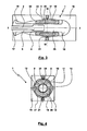
- the handle in the in 10 and 11 illustrated embodiment is constructed as follows: a shaft 2 is covered by a handle core 6, the end portions 17, 18 and a central region 26 has.
- the central region 26 has a substantially cylindrical lateral surface, which is encased by a grip core jacket 9. From the handle core 6 extend, integrally formed by this, ribs 8 through the handle core jacket 9 therethrough, wherein for the in Fig. 11 illustrated cross section, the ribs 8 are arranged in the 12 o'clock position and 6 o'clock position.
- the ribs 8 and the handle core sheath 9 are continuously encased by a soft layer 10 in the circumferential direction, wherein the soft layer 10 in turn by an outer layer 11 which is circumferentially formed circumferentially and forms the lateral surface 14, is sheathed.
- the soft layer 10 forms an inner layer 28 of a soft plastic, on the outside of the outer layer 11, an outer harder layer 27 is bonded cohesively.
- An additional layer 9 of the first material 22 and thus the material of the outer layer 27 forms a handle core sheath 9.
- ribs 8 are attached in one piece. In the in Fig.
- the outer contour of the ribs 8 extends parallel to the outer contour of the lateral surface 14, so that the radial extent of the inner layer 28 of the handle 1 in the direction of the longitudinal axis 3-3 is approximately constant.
- the ribs 8 extend only over an axial portion of the outer layer 27, so that in a front region of the handle 1, the outer layer 27 is directly bonded to the grip core sheath 9 cohesively.
- the ribs 8 can, as in Fig. 11 sketched, be arranged opposite or deviating arranged offset in a manner not shown in the circumferential direction.
- the ribs 8 have a rectangular cross-section, which may deviate also have any other shape, such as slightly tapering outward, rounded at the top or in thickness can be made smaller.
- the use of a plastic having a hardness of 30 to 85 Shore A, preferably 40 to 60 Shore A has proven to be useful - for the soft layer 10 or inner layer 28 has a hardness of 10 to 55 Shore A, preferably from 15 to 30 Shore A.
- Plastics of the same type or of different types can be used, as long as they form a good material connection with one another.
- UU is also responsible for a good material connection between an upper edge of the rib 8 and the outer layer 27 care.
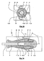
- FIGS. 12 and 13 show further embodiment of a handle 1, wherein in otherwise 10 and 11 corresponding design of the handle core 6 without ribs 8 is formed. Instead, the handle core 6 is formed with an approximately rectangular cross-section, which is completely surrounded in the circumferential direction of the handle core sheath 9 at least in a partial area. Such a rectangular cross section of the handle core 6 extends approximately over the longitudinal extent 29, preferably with a varying ratio of the length to the width of the rectangle or decreasing length of the rectangle.
- the inner layer 28 which is formed with the soft layer 10, star-shaped with six points corresponding to such an outer contour of the handle core 6 and the handle core sheath 9 is formed.
- the inner layer 28 has a maximum radial extent in the positions 12 o'clock, 2 o'clock, 4 o'clock, 6 o'clock, 8 o'clock, 10 o'clock.
- a lateral surface 14 and the structure of the handle 1 in an asymmetrical manner such as in the handle for a trowel, sa FIGS. 23 and 24
- the handle core 6 is expediently kept substantially the same over its longitudinal extension.
- FIGS. 15 and 16 show an embodiment for which ribs 8, 12 extend through the inner layer 28.
- the ribs 8, 12 formed by the handle core 6 are connected in a material-locking manner to the outer layer 11 or outer layer 27 in the region of their end faces and thus represent a direct and rigid connection between outer layer 11 and the otherwise round cross-section of the handle core 6.
- the example shows a thicker outer layer 11 or outer layer 27, as shown by greater cooling of the wall of the Mold cavity is achieved.
- the radial extent 41 of the outer layer 27 is 30% to 100% of the radial extent 40 of the inner layer 28, measured at the location of the largest diameter of the handle first
- Fig. 17 shows an embodiment of a handle 1, which is substantially in the FIGS. 15 and 16 illustrated embodiments, but in this case with a handle core 6 with rectangular transfer section 7, which is firmly bonded to the outer layer 11 and outer layer 27.
- Fig. 18 shows an embodiment of a handle in which a handle core 6 is formed with end portions 17, 18, wherein the end portion 18 forms a cap for applying axial forces by a hand of the user.
- the grip core 6 has six ribs 13 which are uniformly distributed over the circumference.
- the outer layer 11 (outer layer 27) and the grip core sheath 9 are configured as a circular collar over a radial web 42 which is circumferential in the circumferential direction for the exemplary embodiment shown. connected to each other, so that with the grip core jacket 9, the web 42 and the outer layer 11 in the half-longitudinal section a lying, open at the front U is formed.
- the inner leg of the U which forms the Griffkernummantelung 9 is formed shorter than the outer, the lateral surface 14 forming legs, which is formed in particular approximately with the longitudinal extent 29.
- the Griffkernummantelung 9 is penetrated by the ribs 8, 13.
- a soft layer 10 is arranged, which forms an inner layer 28.
- the handle core 6 is formed of a hard plastic defining a first stiffness. With the end portions 17 and 18, during manufacturing of the handle 1, the handle core 6 seals against the wall of a mold cavity when the handle core jacket 9 and the soft layer 10 are formed by spraying onto the handle core 6.
- the outer layer 11 has a third rigidity. while the soft layer 10 has a second stiffness.
- the second and third stiffnesses are formed with an elastic plastic of different hardness, wherein the plastic used for the third rigidity has a higher hardness than the plastic used to provide the second rigidity.
- a manufacture of the handle 1 is carried out such that first the handle core 6 is manufactured in a first injection mold, wherein the shaft 2 is poured into the handle core 6.
- the handle core sheath 9, the soft layer 10 and the outer layer 11 are sprayed onto the inserted into the mold handle core 6 according to the interval sandwich method.
- the first material 22 forming the handle core jacket 9, the web 42 and the outer layer 11 is injected into the mold and immediately thereafter before curing the plastic mass forming the soft layer 10 (inner layer 28), the second material 23 , injected.
- the second material 23 displaces the first injected, still (partially) liquid first material 22 against the wall of the mold cavity or against the wall of the handle core 6, whereby the handle core jacket 9, the web 42 and the outer layer 11 are formed.
- the outer layer 11 can form a dense layer.
- the thickness of this layer may be controlled by the process flow, for example, the ratio and dosage amounts of the materials 22, 23, and / or the parameters of the injection molding operation.
- the thickness of the layer is adjusted in each case so that a radial deformability of the outer layer 11 and the soft layer 10 under the action of a force by the handle enclosing the hand 1 is not diminished when working, but on the other hand a good transmission of an initiated torsional moment is ensured as it is z. B. when using such a handle for a screwdriver is required. It has been found that a layer thickness of approximately 0.5 to 2.5 mm is expedient for the outer layer 11, wherein the thickness may vary in the course of the lateral surface 14.
- a quality or type of plastic used which has a sufficient for the application resistance to chemicals, fats or oils.
- Such resistance need not necessarily have the plastic types used for the soft layer 10, whereby u. U. costs can be saved.
- a pairing of the materials 22, 23 in hardness and type or type is chosen such that they are on the one hand a good material connection with each other and with the handle core 6 and on the other hand, a desired deformability is ensured.
- the lateral surface 14 is formed with the radially enlarged end portions 17, 18 of the handle core 6.
- an elastic part of the handle 1 is arranged, which is formed with a soft layer 10 (inner layer 28) and a jacket of the soft layer 10 closed in longitudinal section with the handle core jacket 9 and the outer layer 11 (outer layer).
- This elastic grip part can either be manufactured first as a separate injection-molded part - also in a sandwich process - and be plugged under elastic expansion from the rear over the end region 18 onto the grip core 6 or the grip part is sprayed directly onto the grip core 6 in a sandwich process, as already described above Embodiments has been described.
- Fig. 20 illustrated embodiment is formed in the handle 1 of the handle core 6 is not continuous to the end of the handle 1. Rather, the end region 18 of the handle core 6 is also encased by the handle core jacket 9, the soft layer 10 (inner layer 28) and the outer layer 11 (outer layer 27), so that the outer layer 11 also forms the end-side lateral surface or the cap.
- the handle core 6 is carried out without radial thickening in the end portion 18 to the end of the handle 1.
- the soft layer 10 or inner layer 28 is formed in particular with a second material 23 in the form of a plastic in a closed structure with a hardness of 10 to 45 Shore A.
- the soft layer 10 may be formed with a porous structure whose initial hardness is 20 to 80 Shore A.
- the outer layer 11 (outer layer 27) and / or the Griffkernummantelung 9 finds a first material in the form of a plastic insert with a hardness of 30 to 105 Shore A, in particular 30 to 85, preferably 40 to 60 Shore A.
- the radial extent of soft layer 10 is greater than that of the outer layer 11 and / or the Griffkernummantelung 9.
- the thickness of the Griffkernummantelung 9 and / or the outer layer 11 is between 0.5 and 4 mm.
- the handle core 6 may have a crowned end of the handle forming cap whose diameter is greater than the diameter of a shaft or central region 26 of the handle core 6.
- the handle core 6 may have no crowned cap and with the shaft or center region 26 to the end of the handle 1 have a continuous constant cross-section.
- the handle core can not be formed continuously to the end of the handle 1.
- the in the FIGS. 22 to 24 illustrated embodiment of a handle is used for a trowel 46.
- the handle 1 has according to the in Fig. 23 longitudinal section shown a front end portion 47, a central portion 26 and a rear end portion 48.
- the end portions 47, 48 are each formed by radial extensions of the handle core 6.
- the middle region 26 is formed, according to the previously illustrated embodiments, with a handle core sheath 9, a soft layer 10 (inner layer 28) of the second material 23, and an outer layer 11 (outer layer 27) of the first material 22, for the illustrated embodiment outer layer 11 and grip core sheath 9 in the transition region to the end regions 47, 48 by webs 42 or each a collar-like end-side layer are firmly bonded to each other, so that the soft layer 10 is completely encased by a layer of the harder material 22.
- the handle core sheath 9, the soft layer 10, and the outer layer 11 are made by injecting the materials 22, 23 in a sandwich process. From the in Fig. 24 illustrated cross-section of the handle 1 can be seen that this is asymmetrical to a transverse to the longitudinal axis 3-3 oriented transverse axis 49-49. Of course, the handle can also have a symmetrical shape.
- FIGS. 18 to 26 show, inside the handles 1 is not necessarily continuous web or rib-like connections between the Griffkernummantelung 9 and the outer layer 11 of material 22, since such a web-like connection does not automatically results in each case in the sandwich process.
- FIGS. 25 and 26 illustrated embodiment are provided in the representation of the lower half-plane ribs 8, 13 of the handle core 6, which pass through the Griffkernummantelung 9 in both radial directions and in a portion of the soft layer 10 (inner layer 27), as can be seen Fig. 26 is apparent.
- six ribs 8, 13 are uniformly distributed in the circumferential direction, wherein two opposite ribs 8, 13 are formed with respect to the other ribs 8, 13 enlarged radial extent. But it can also all ribs have the same radial extent.
- Fig. 28 shows an embodiment of a handle 1 for a pliers leg 25, see also Fig. 7, 8, 9 .
- a lower part 51 in which the pliers limb 25 is received, is covered with a hard plastic.
- an upper part 52 Connected to the lower part 51 in a material-locking manner on the outer side of the pliers limb 25 is an upper part 52, wherein in this connection the lower part 51 is comparable to the grip core 6 of the exemplary embodiments of screwdrivers.
- the top 52 is formed with a soft layer 10 or inner layer 28 completely surrounded in cross-section by that of an outer layer 11 or outer layer and a "handle core jacket" 9 which merge into one another.
- a manufacture of the handle 1, consisting of the upper part 52 in conjunction with the lower part 51, is possible both as a separate part for subsequent mounting on the pliers limb 25 and by direct spraying onto the pliers limb 25 in a sandwich method, comparable to the spraying of the layers 10 and 11 on the handle core 6 of a screwdriver.
- Fig. 29, 30th show a hammer 53 with an embodiment of a handle 1 in longitudinal section and cross section. At least in the region of the handle that is grasped by the user by hand, the handle 1 is formed with a handle core sheath 9, a soft layer 10 (inner layer 27), and an outer layer 11 (outer layer 28) that are sandwiched can be made. Notwithstanding the illustrated embodiment, a hammer handle can also be equipped with a close fitting in a cavity tail similar to a cap 18 in a handle for screwdrivers.
- FIGS. 31 and 32 illustrated embodiment is made without handle core 9 from a hard plastic.
- the handle core 6 with the associated, opposing two ribs 8, 13 directly or indirectly with the interposition of the Griffkernummantelung 9 with a soft layer 10 (inner layer 28) sheathed, which is formed for production in a sandwich process with a second material 23.
- the soft layer 10 is encased radially outwardly of the outer layer 11 (outer layer 27), which is suitable for fabrication in the sandwich process with the first material 22 is formed.
- the thickness of the outer layer 11 is set in this embodiment by appropriate dosage of injected into the mold cavity volumes of the materials 22 and 23 and more cooling the wall of the mold cavity, preferably, depending on the handle size, in the range between 2 and 4 mm.
- connection of the layers 27, 28 thereby already obtains a good torsional stiffness, even if the ribs 8, 13 do not extend far into the soft layer 10.
- a further improvement of the torsional rigidity is achieved by extending the ribs 8 to approximately the inside of the outer layer 11 (outer layer 27). In extreme cases, the ribs connect firmly to the outer layer 27, s.
- FIGS. 15, 16 An increase in the torsional rigidity can also be brought about by the fact that the handle core 6 itself has an approximately rectangular cross-section and connects to the inside of the outer layer 11 in a material-locking manner, see FIG. Fig. 17 ,
- Fig. 33 shows an embodiment of the method according to the invention, in which three inlet openings 20, 21, 54 are distributed uniformly in the circumferential direction approximately at the same axial position. In this way, three ribs 12 can be produced in the circumferential direction centrally between the inlet openings 20, 21, 54, which extend in axially and radially oriented planes.
- Fig. 34 shows an embodiment of the method according to the invention, in which two inlet openings 20, 21 are arranged on the circumference opposite each other, but are arranged offset from one another in the axial direction.
- a rib 12 sets in, which is closed in the circumferential direction or in the form of a spiral running around the longitudinal axis 3-3 and connects the layers 9 and 11.
- the resulting rib 12 extends in a plane lying transversely to the longitudinal axis, while for the illustrated embodiment a pitch angle ⁇ of the spiral with respect to the longitudinal axis 3-3 results ,
- the pitch angle ⁇ of the spiral can be specified.
- the invention relates not only handles for different tools, but also one or more handles for tool sets in different sizes and shank shapes.
- handles for screwdrivers a non-porous design of the layers is preferred.
- the inventive method can for the production of handles with symmetrical cross-sectional shapes, such as screwdriver handles, but also for handles with asymmetrical cross-sectional shapes, such as Trowel handles or hammer handles according to EP 00 907 448.5 and EP 01 915 000.2 Applicant be applied.
- it is characteristic of handles made by this method that the cross-sectional area of the hard plastic handle core is relatively small relative to the cross-sectional area of the finished handle, thereby achieving a relatively large volume of resilient, soft layers can be. In this way, these handles differ from the prior art 2-component handles, in which the cross-sectional area of the handle core made of hard plastic is relatively large compared to the cross-sectional area of the handle shell made of a softer plastic.
- injection of the first material (22) and second material (23) may be via the same inlet (s) (20, 21).
- first material (22) and second material (23) without interrupting the flow of material are injected in chronological succession.
- first material (22) a thermoplastic elastomer, a thermoplastic polyolefin, polypropylene, EPDM rubber, PVC, styrene block copolymer can be injected.
- the outer layer (27) has a filler.
- the lateral surface (14) of the handle (1) can also be formed with a film which is firmly bonded to an inner layer.
- an outer layer (27) may have a substantially constant thickness of at most 4 mm, at least in the region of an axial extent (29).
Landscapes
- Engineering & Computer Science (AREA)
- Mechanical Engineering (AREA)
- Manufacturing & Machinery (AREA)
- Injection Moulding Of Plastics Or The Like (AREA)
- Percussive Tools And Related Accessories (AREA)
- Gripping Jigs, Holding Jigs, And Positioning Jigs (AREA)
- Knives (AREA)
- Ceramic Products (AREA)
- Mechanical Control Devices (AREA)
- Credit Cards Or The Like (AREA)
Claims (23)
- Procédé pour la réalisation d'un manche (1) pour un outil, avec un noyau de manche (6) en matériau dur, une couche extérieure (27) réalisée dans un premier matériau souple (22) et une couche intérieure (28) radialement adjacente à la couche extérieure (27), laquelle est située à l'intérieur à partir de la couche extérieure (27) et est réalisée dans un deuxième matériau souple (23), l'épaisseur et la rigidité des couches (27, 28) étant choisies de telle sorte que lorsque le manche (1) est sollicité par la force d'une main d'un utilisateur, il se produit une déformation élastique tant de la couche extérieure (27) que de la couche intérieure (28), comportant les étapes suivantes :a) un premier matériau (22) est injecté d'abord dans un moule (16), etb) à la suite de l'injection du premier matériau (22) et avant le durcissement définitif du premier matériau (22), un deuxième matériau (23) est injecté dans le moule (16) dans le premier matériau (22) encore liquide, sachant que, sous l'effet de l'injection du deuxième matériau (23), le premier matériau (22) est repoussé dans l'espace et vient en appui contre la paroi du moule (16),c) à la suite d'un durcissementca) la couche extérieure (27) est formée avec le premier matériau (22) etcb) la couche intérieure (28) est formée avec le deuxième matériau (23),d) caractérisé en ce que, avant le durcissement définitif du premier matériau (22), le deuxième matériau (23) est injecté dans le moule (16) à partir d'au moins une ouverture d'injection, de préférence au moins deux ouvertures d'injection (20, 21) orientées radialement, avec un flux de matière formé de flux partiels opposés entre eux, de telle sorte que le premier matériau (22)da) est repoussé partiellement par le deuxième matériau (23) vers l'extérieur et y forme, après le durcissement, au moins des zones partielles d'une surface d'enveloppe (14) du manche (1), etdb) le premier matériau (22) subsiste au moins dans une zone périphérique partielle, dans laquelle se rencontrent des flux partiels opposés, moyennant quoi, après un durcissement, il se forme avec le premier matériau (22) dans la zone périphérique partielle une arête, une saillie ou une nervure ou des arêtes, des saillies ou des nervures (12), laquelle ou lesquelles est/sont reliée(s) par liaison de matière contre la couche extérieure (27) et/ou une couche interne (enveloppe 9 du noyau du manche).
- Procédé selon la revendication 1, caractérisé en ce que la couche intérieure (28) et la couche extérieure (27) sont réalisées avec une structure fermée.
- Procédé selon la revendication 1 ou 2, caractérisé en ce que le deuxième matériau (23) est plus souple que le premier matériau (22).
- Procédé selon l'une quelconque des revendications 1 à 3, caractérisé en ce que, à la suite de l'injection du premier matériau (22) et avant le durcissement définitif du premier matériau (22), le deuxième matériau (23) est injecté dans le moule (16) avec un flux de matière tel que le premier matériau (22)a) est repoussé partiellement par le deuxième matériau (23) vers l'extérieur et, après le durcissement, y forme au moins des zones partielles d'une surface d'enveloppe (14) du manche (1), etb) est repoussé partiellement par le deuxième matériau (23) vers l'intérieur et, après le durcissement, y forme au moins des zones partielles d'une couche interne (enveloppe 9 du noyau du manche).
- Procédé selon la revendication 1, caractérisé en ce que dans la zone périphérique partielle, dans laquelle se rencontrent des flux partiels opposés, des couches de bordure refroidies du premier matériau (22) ne sont pas repoussées ou enlevées par fusion, mais fusionnent, moyennant quoi, après un durcissement, il se forme avec le premier matériau (22) dans la zone périphérique partielle une arête, une saillie ou une nervure ou des arêtes, des saillies ou des nervures (12), laquelle ou lesquelles est/sont reliée(s) par liaison de matière contre la couche extérieure (27) et/ou une couche interne (enveloppe 9 du noyau du manche).
- Procédé selon l'une quelconque des revendications précédentes, caractérisé en ce qu'il est prévu deux ouvertures d'injection (20, 21) opposées l'une à l'autre dans la direction circonférentielle.
- Procédé selon l'une quelconque des revendications précédentes, caractérisé en ce qu'il est prévu une seule ouverture d'injection (20 ; 21).
- Procédé selon l'une quelconque des revendications précédentes, caractérisé en ce qu'un noyau de manche (6) est posé dans le moule (16) avant l'injection des matériaux (22, 23).
- Procédé selon la revendication 8, caractérisé en ce que le noyau de manche (6) comporte un oeillet (15), et le noyau de manche (6) est posé dans le moule (16) et est orienté par rapport aux ouvertures d'injection (20, 21), de telle sorte que l'oeillet (15) se situe dans la zone périphérique partielle, dans laquelle sont formées les arêtes, les saillies ou les nervures (12).
- Procédé selon la revendication 8 ou 9, caractérisé en ce que le noyau de manche (6) comporte des nervures (8) orientées radialement vers l'extérieur, et le noyau de manche (6) est posé dans le moule (16) de telle sorte que les nervures (8) s'étendent dans la zone périphérique partielle, dans laquelle se rencontrent les flux partiels opposés et sont formées les arêtes, saillies ou nervures (12).
- Procédé selon l'une quelconque des revendications précédentes, caractérisé en ce qu'un plan de séparation du moule (16) est situé en étant décalé d'environ 90° par rapport à la zone périphérique partielle, dans laquelle se rencontrent les flux partiels opposés et sont formées les arêtes, saillies ou nervures (12).
- Procédé selon l'une quelconque des revendications 8 à 11, caractérisé en ce que le noyau de manche (6) comporte deux zones d'extrémité (17, 18) opposées qui forment les zones partielles d'extrémité de la surface d'enveloppe (14), sachant que les zones d'extrémité (17, 18), le noyau de manche (6) ou l'enveloppe (9) du noyau du manche et le moule (16) avant l'injection des matériaux (22, 23) délimitent une chambre (19).
- Procédé selon l'une quelconque des revendications précédentes, caractérisé en ce que l'outil est une pince avec deux branches (25), qui sont entourées chacune d'un manche (1), une ouverture d'injection (20) pour le premier matériau (22) et le deuxième matériau (23) étant disposée sur chacune des faces des branches (25), orientées l'une vers l'autre dans la position montée, ou au niveau de l'extrémité arrière ou avant du manche.
- Procédé selon l'une quelconque des revendications précédentes, caractérisé en ce que l'on injecte un premier matériau (22) dont la dureté se situe entre 25 et 90 Shore A, de préférence 30 et 85 Shore A, en particulier 30 à 60 Shore A.
- Procédé selon l'une quelconque des revendications précédentes, caractérisé en ce que l'on injecte un deuxième matériau (23) dont la dureté est de l'ordre de 10 à 40 Shore A, de préférence de 15 à 35 Shore A.
- Procédé selon l'une quelconque des revendications précédentes, caractérisé en ce que les conditions d'injection sont définies de telle sorte qu'il se forme deux zones périphériques partielles avec une extension radiale réduite de la couche intérieure (28).
- Procédé selon l'une quelconque des revendications précédentes, caractérisé en ce que sur le noyau de manche (6) sont prévues des nervures (8) qui s'étendent jusqu'à la face intérieure de la couche extérieure (27).
- Procédé selon l'une quelconque des revendications 1 à 16, caractérisé en ce que l'on insère un noyau de manche (6) avec une section de forme sensiblement rectangulaire, dont le côté plus long s'étend jusqu'à une faible distance de la couche extérieure (27).
- Procédé selon l'une quelconque des revendications précédentes, caractérisé en ce que des ouvertures d'injection (20, 21) pour les matériaux (22, 23) sont disposées en étant décalées dans la direction axiale l'une par rapport à l'autre.
- Manche pour un outil, en particulier un tournevis, comportant les caractéristiques et réalisé avec un procédé selon l'une des revendications 1 à 12 ou 14 à 19.
- Manche selon la revendication 20, caractérisé en ce qu'une couche extérieure (27) a une épaisseur entre 0,5 et 4 mm.
- Manche selon la revendication 20 ou 21, caractérisé en ce que l'extension radiale de la couche intérieure (28), au moins au niveau de l'emplacement du plus grand diamètre du manche, est supérieure à l'extension radiale de la couche extérieure (27).
- Manche selon la revendication 20, 21 ou 22, caractérisé en ce qu'au moins au même emplacement, un rapport entre le plus grand diamètre (D = 2.0 x rayon (34)) du manche (1) et le diamètre (d = 2.0 x rayon (33)) d'un noyau de manche est supérieur à 1,5, en particulier est supérieur à 2.
Priority Applications (1)
| Application Number | Priority Date | Filing Date | Title |
|---|---|---|---|
| EP06762146A EP1963072B1 (fr) | 2005-12-23 | 2006-06-23 | Procede de production d'un manche |
Applications Claiming Priority (8)
| Application Number | Priority Date | Filing Date | Title |
|---|---|---|---|
| PCT/EP2005/014003 WO2006069759A1 (fr) | 2004-12-23 | 2005-12-23 | Poignee |
| DE102005063035 | 2005-12-29 | ||
| DE102006002594 | 2006-01-18 | ||
| DE102006010397 | 2006-03-03 | ||
| DE102006012576 | 2006-03-16 | ||
| DE102006022019 | 2006-05-10 | ||
| EP06762146A EP1963072B1 (fr) | 2005-12-23 | 2006-06-23 | Procede de production d'un manche |
| PCT/EP2006/006045 WO2007079787A1 (fr) | 2005-12-23 | 2006-06-23 | Procede de production d'un manche |
Publications (2)
| Publication Number | Publication Date |
|---|---|
| EP1963072A1 EP1963072A1 (fr) | 2008-09-03 |
| EP1963072B1 true EP1963072B1 (fr) | 2011-04-13 |
Family
ID=40785301
Family Applications (1)
| Application Number | Title | Priority Date | Filing Date |
|---|---|---|---|
| EP06762146A Active EP1963072B1 (fr) | 2005-12-23 | 2006-06-23 | Procede de production d'un manche |
Country Status (6)
| Country | Link |
|---|---|
| EP (1) | EP1963072B1 (fr) |
| JP (1) | JP4616394B2 (fr) |
| CN (1) | CN101384413B (fr) |
| AT (1) | ATE505312T1 (fr) |
| DE (1) | DE502006009314D1 (fr) |
| WO (1) | WO2007079787A1 (fr) |
Cited By (3)
| Publication number | Priority date | Publication date | Assignee | Title |
|---|---|---|---|---|
| CN102554943A (zh) * | 2010-12-17 | 2012-07-11 | 李积回 | 防震刀具 |
| EP3456483A1 (fr) | 2017-09-18 | 2019-03-20 | Felo-Werkzeugfabrik Holland-Letz GmbH | Outil à main et procédé de fabrication d'un outil à main |
| EP4163060A1 (fr) * | 2021-10-05 | 2023-04-12 | Hilti Aktiengesellschaft | Poignée supplémentaire pour une machine-outil portative |
Families Citing this family (33)
| Publication number | Priority date | Publication date | Assignee | Title |
|---|---|---|---|---|
| US8499665B2 (en) * | 2006-08-30 | 2013-08-06 | Stanley Black & Decker, Inc. | Torsion control hammer grip |
| JP4793870B2 (ja) * | 2006-10-26 | 2011-10-12 | 三菱鉛筆株式会社 | 複合部材 |
| EP1927455A1 (fr) * | 2006-11-28 | 2008-06-04 | Koninklijke Philips Electronics N.V. | Procédé pour fabriquer un élément de boîtier avec une surface décorative et une couche de prise, feuille décorative et élément de boîtier |
| DE102007038928B4 (de) * | 2007-08-17 | 2010-06-10 | Felo-Werkzeugfabrik Holland-Letz Gmbh | Werkzeug |
| DE202007013989U1 (de) | 2007-10-05 | 2009-02-12 | Felo-Werkzeugfabrik Holland-Letz Gmbh | Griff zur Übertragung eines Torsionsmomentes oder einer Druckkraft |
| EP2045046B1 (fr) | 2007-10-05 | 2010-09-01 | Felo-Werkzeugfabrik Holland-Letz GmbH | Poignée pour un outil |
| DE102008010755B4 (de) | 2007-10-05 | 2010-04-15 | Felo-Werkzeugfabrik Holland-Letz Gmbh | Griff für ein Werkzeug |
| US8006349B2 (en) * | 2008-09-29 | 2011-08-30 | Eaton Corporation | Lightweight grip and method of making same |
| JP4440327B1 (ja) * | 2009-03-13 | 2010-03-24 | 株式会社ベッセル工業 | グリップ、工具及びグリップの製造方法 |
| US8296907B2 (en) * | 2009-05-15 | 2012-10-30 | Eaton Corporation | Light weight grip and method of making same |
| DE202009010760U1 (de) * | 2009-08-10 | 2009-10-08 | Eduard Wille Gmbh & Co. Kg | Werkzeuggriffhülle |
| CN101992462B (zh) * | 2009-08-14 | 2015-08-19 | 杭州巨星科技股份有限公司 | 工具手柄及其制造方法 |
| FI20096245A7 (fi) * | 2009-11-26 | 2011-05-27 | Fiskars Brands Finland Oy Ab | Käsityökalun kahva ja menetelmä kahvan valmistamiseksi |
| FI20096328L (fi) | 2009-12-15 | 2011-06-16 | Fiskars Brands Finland Oy Ab | Menetelmä käsityökalun kädensijan valmistamiseksi ja käsityökalun kädensija |
| DE102011101843A1 (de) * | 2011-05-17 | 2012-11-22 | Webasto Ag | Kunststoffbauteil eines Fahrzeugs mit einem Einlegeteil |
| JP3181045U (ja) * | 2012-11-05 | 2013-01-24 | 株式会社ベッセル工業 | 木粉を用いたグリップ部を備えた工具 |
| US9213409B2 (en) * | 2013-11-25 | 2015-12-15 | Immersion Corporation | Dual stiffness suspension system |
| US10370156B2 (en) * | 2014-08-07 | 2019-08-06 | Becton, Dickinson And Company | One-piece safety tube closure with film element |
| TWI588005B (zh) * | 2014-12-31 | 2017-06-21 | Yang Bey Industrial Co Ltd | Hand tools multi-color handle manufacturing methods |
| US9802347B2 (en) | 2015-02-02 | 2017-10-31 | Colgate-Palmolive Company | Method of forming an oral care implement |
| CN106671013A (zh) * | 2015-11-05 | 2017-05-17 | 蔡清钦 | 起子握把结构 |
| CN105196469B (zh) * | 2015-11-10 | 2017-07-21 | 苏州盛康塑胶电器有限公司 | 宠物梳加工工艺 |
| CN108115619B (zh) * | 2016-11-30 | 2024-11-26 | 杭州巨星工具有限公司 | 一种手柄和锤击工具 |
| TWI621509B (zh) * | 2017-05-05 | 2018-04-21 | Whirlpower Enterprise Co Ltd | Hand tool handle structure improvement |
| US11110585B2 (en) | 2017-11-02 | 2021-09-07 | Stanley Black & Decker, Inc. | Grip component for a hand tool |
| US10583550B2 (en) | 2017-11-02 | 2020-03-10 | Stanley Black & Decker, Inc. | Grip component for a hand tool |
| TWI650209B (zh) * | 2018-03-09 | 2019-02-11 | 劉再發 | 手工具把手結構改良(一) |
| WO2020218159A1 (fr) * | 2019-04-24 | 2020-10-29 | 株式会社永木精機 | Outil ayant un mécanisme à cliquet ayant d'excellentes propriétés antirouille |
| IT201900024099A1 (it) * | 2019-12-16 | 2021-06-16 | Complastic S R L | Metodo di costampaggio a bi-iniezione e prodotto così ottenuto |
| US11660738B2 (en) | 2020-12-09 | 2023-05-30 | Stanley Black & Decker, Inc. | Ergonomic grip for striking tool |
| CN112873706B (zh) * | 2020-12-30 | 2024-12-27 | 富联裕展科技(深圳)有限公司 | 金属塑胶复合件、制作方法、壳体及电子设备 |
| TWI889579B (zh) * | 2024-10-21 | 2025-07-01 | 穩陞工業股份有限公司 | 扳手結構 |
| CN119217637B (zh) * | 2024-12-03 | 2025-07-11 | 常州宣康文体用品有限公司 | 一种橡胶手把护套成型设备及其成型工艺 |
Family Cites Families (12)
| Publication number | Priority date | Publication date | Assignee | Title |
|---|---|---|---|---|
| DE9202550U1 (de) * | 1992-02-27 | 1992-05-07 | Felo-Werkzeugfabrik Holland-Letz GmbH, 3577 Neustadt | Werkzeughandgriff, insbesondere für Schraubendreher |
| JP2860440B2 (ja) * | 1993-09-28 | 1999-02-24 | モリト株式会社 | ハンドル、握り部等に使用するグリップ |
| JPH08267490A (ja) * | 1995-03-28 | 1996-10-15 | Toyoda Gosei Co Ltd | 樹脂成形品 |
| FR2754204B1 (fr) * | 1996-10-04 | 1998-12-18 | Bost Garnache Ind | Procede de fabrication d'une branche d'outil, et gamme de pinces correspondante |
| DE29705522U1 (de) * | 1997-03-27 | 1998-07-23 | Eerenstein, Peter, 42699 Solingen | Kunststoffummantelung für den Zangengriff einer Zange |
| US6368536B1 (en) * | 1997-09-15 | 2002-04-09 | Snap-On Technologies, Inc. | Method of forming tool with dual-material handle |
| GB9909101D0 (en) * | 1999-04-22 | 1999-06-16 | Smithkline Beecham Gmbh & Co | Toothbrush |
| DE10013627A1 (de) * | 2000-03-18 | 2001-09-27 | Pts Plastic Technologie Servic | Verfahren zur Herstellung von Weich/Weich- Sandwichteilen auf flachen Formteilen |
| JP2002292682A (ja) * | 2001-03-30 | 2002-10-09 | Sumitomo Chem Co Ltd | 多層射出成形体の製造方法および多層射出成形体 |
| DE10157998A1 (de) * | 2001-11-27 | 2003-06-05 | Adolf Wuerth Gmbh & Co Kg | Handgriff für Werkzeuge |
| US20030172498A1 (en) * | 2002-03-15 | 2003-09-18 | Polzin Bruce C. | Apparatus to cushion and dampen vibration and method |
| DE20310882U1 (de) * | 2002-07-16 | 2003-10-09 | Dura Automotive Systems Gmbh | Schaltknauf |
-
2006
- 2006-06-23 EP EP06762146A patent/EP1963072B1/fr active Active
- 2006-06-23 AT AT06762146T patent/ATE505312T1/de active
- 2006-06-23 WO PCT/EP2006/006045 patent/WO2007079787A1/fr not_active Ceased
- 2006-06-23 CN CN2006800532721A patent/CN101384413B/zh active Active
- 2006-06-23 JP JP2008546152A patent/JP4616394B2/ja active Active
- 2006-06-23 DE DE502006009314T patent/DE502006009314D1/de active Active
Cited By (4)
| Publication number | Priority date | Publication date | Assignee | Title |
|---|---|---|---|---|
| CN102554943A (zh) * | 2010-12-17 | 2012-07-11 | 李积回 | 防震刀具 |
| EP3456483A1 (fr) | 2017-09-18 | 2019-03-20 | Felo-Werkzeugfabrik Holland-Letz GmbH | Outil à main et procédé de fabrication d'un outil à main |
| EP4163060A1 (fr) * | 2021-10-05 | 2023-04-12 | Hilti Aktiengesellschaft | Poignée supplémentaire pour une machine-outil portative |
| WO2023057241A1 (fr) * | 2021-10-05 | 2023-04-13 | Hilti Aktiengesellschaft | Poignée auxiliaire pour un outil électrique portatif |
Also Published As
| Publication number | Publication date |
|---|---|
| DE502006009314D1 (de) | 2011-05-26 |
| WO2007079787A1 (fr) | 2007-07-19 |
| WO2007079787A8 (fr) | 2008-08-07 |
| EP1963072A1 (fr) | 2008-09-03 |
| JP2009520609A (ja) | 2009-05-28 |
| JP4616394B2 (ja) | 2011-01-19 |
| CN101384413B (zh) | 2011-04-27 |
| CN101384413A (zh) | 2009-03-11 |
| ATE505312T1 (de) | 2011-04-15 |
Similar Documents
| Publication | Publication Date | Title |
|---|---|---|
| EP1963072B1 (fr) | Procede de production d'un manche | |
| EP1827766B1 (fr) | Poignee | |
| EP1923194B1 (fr) | Procédé de fabrication d'un manche | |
| EP0644817B1 (fr) | Manche pour outils, en particulier pour tournevis | |
| DE69821176T2 (de) | Werkzeug mit Griff aus zwei Werkstoffen | |
| EP1837130B1 (fr) | Poignée pour un outil | |
| JP2009520609A5 (fr) | ||
| EP3233384B1 (fr) | Poignée supplémentaire | |
| EP0627974B1 (fr) | Procede de fabrication d'un manche d'outil et outil permettant de mettre le procede en uvre | |
| WO2002000396A1 (fr) | Outil de serrage et desserrage de vis et d'ecrous et son procede de production | |
| WO2007048555A1 (fr) | Poignée pour outil transmetteur de couple de torsion | |
| DE202007003351U1 (de) | Handgriff für ein Werkzeug | |
| DE102006032537A1 (de) | Verfahren zur Herstellung eines Griffes | |
| EP1979135B1 (fr) | Poignée pour outil transmetteur de couple de torsion | |
| DE19856986A1 (de) | Bohrwerkzeug für Werkzeugmaschinen sowie Verfahren zu dessen Herstellung | |
| DE102006038636A1 (de) | Verfahren zur Herstellung eines Griffes für einen Schraubendreher und Schraubendreher | |
| DE9202550U1 (de) | Werkzeughandgriff, insbesondere für Schraubendreher | |
| DE10042859C2 (de) | Griffsatz für ein Hand- oder Gartenwerkzeug | |
| DE4304965C2 (de) | Verfahren zur Herstellung eines Werkzeughandgriffes und Werkzeug zur Durchführung des Verfahrens | |
| DE202006005503U1 (de) | Handgriff für Werkzeuge | |
| DE202005021195U1 (de) | Schraubendreher | |
| DE102005055981A1 (de) | Handgriff für Werkzeuge und Betätigungselemente | |
| EP2045046B1 (fr) | Poignée pour un outil | |
| DE102006054477B4 (de) | Schraubendreher mit Griff | |
| WO2007079979A2 (fr) | Manche pour transferer un couple de torsion ou un effort de pression |
Legal Events
| Date | Code | Title | Description |
|---|---|---|---|
| PUAI | Public reference made under article 153(3) epc to a published international application that has entered the european phase |
Free format text: ORIGINAL CODE: 0009012 |
|
| 17P | Request for examination filed |
Effective date: 20080618 |
|
| AK | Designated contracting states |
Kind code of ref document: A1 Designated state(s): AT BE BG CH CY CZ DE DK EE ES FI FR GB GR HU IE IS IT LI LT LU LV MC NL PL PT RO SE SI SK TR |
|
| GRAP | Despatch of communication of intention to grant a patent |
Free format text: ORIGINAL CODE: EPIDOSNIGR1 |
|
| GRAS | Grant fee paid |
Free format text: ORIGINAL CODE: EPIDOSNIGR3 |
|
| GRAA | (expected) grant |
Free format text: ORIGINAL CODE: 0009210 |
|
| AK | Designated contracting states |
Kind code of ref document: B1 Designated state(s): AT BE BG CH CY CZ DE DK EE ES FI FR GB GR HU IE IS IT LI LT LU LV MC NL PL PT RO SE SI SK TR |
|
| REG | Reference to a national code |
Ref country code: GB Ref legal event code: FG4D Free format text: NOT ENGLISH |
|
| REG | Reference to a national code |
Ref country code: CH Ref legal event code: EP |
|
| REG | Reference to a national code |
Ref country code: IE Ref legal event code: FG4D Free format text: LANGUAGE OF EP DOCUMENT: GERMAN |
|
| REF | Corresponds to: |
Ref document number: 502006009314 Country of ref document: DE Date of ref document: 20110526 Kind code of ref document: P |
|
| REG | Reference to a national code |
Ref country code: DE Ref legal event code: R096 Ref document number: 502006009314 Country of ref document: DE Effective date: 20110526 |
|
| REG | Reference to a national code |
Ref country code: NL Ref legal event code: VDEP Effective date: 20110413 |
|
| REG | Reference to a national code |
Ref country code: SE Ref legal event code: TRGR |
|
| REG | Reference to a national code |
Ref country code: ES Ref legal event code: FG2A Ref document number: 2364282 Country of ref document: ES Kind code of ref document: T3 Effective date: 20110830 |
|
| LTIE | Lt: invalidation of european patent or patent extension |
Effective date: 20110413 |
|
| PG25 | Lapsed in a contracting state [announced via postgrant information from national office to epo] |
Ref country code: PT Free format text: LAPSE BECAUSE OF FAILURE TO SUBMIT A TRANSLATION OF THE DESCRIPTION OR TO PAY THE FEE WITHIN THE PRESCRIBED TIME-LIMIT Effective date: 20110816 Ref country code: LT Free format text: LAPSE BECAUSE OF FAILURE TO SUBMIT A TRANSLATION OF THE DESCRIPTION OR TO PAY THE FEE WITHIN THE PRESCRIBED TIME-LIMIT Effective date: 20110413 |
|
| REG | Reference to a national code |
Ref country code: IE Ref legal event code: FD4D |
|
| PG25 | Lapsed in a contracting state [announced via postgrant information from national office to epo] |
Ref country code: SI Free format text: LAPSE BECAUSE OF FAILURE TO SUBMIT A TRANSLATION OF THE DESCRIPTION OR TO PAY THE FEE WITHIN THE PRESCRIBED TIME-LIMIT Effective date: 20110413 Ref country code: FI Free format text: LAPSE BECAUSE OF FAILURE TO SUBMIT A TRANSLATION OF THE DESCRIPTION OR TO PAY THE FEE WITHIN THE PRESCRIBED TIME-LIMIT Effective date: 20110413 Ref country code: LV Free format text: LAPSE BECAUSE OF FAILURE TO SUBMIT A TRANSLATION OF THE DESCRIPTION OR TO PAY THE FEE WITHIN THE PRESCRIBED TIME-LIMIT Effective date: 20110413 Ref country code: IS Free format text: LAPSE BECAUSE OF FAILURE TO SUBMIT A TRANSLATION OF THE DESCRIPTION OR TO PAY THE FEE WITHIN THE PRESCRIBED TIME-LIMIT Effective date: 20110813 Ref country code: CY Free format text: LAPSE BECAUSE OF FAILURE TO SUBMIT A TRANSLATION OF THE DESCRIPTION OR TO PAY THE FEE WITHIN THE PRESCRIBED TIME-LIMIT Effective date: 20110413 Ref country code: GR Free format text: LAPSE BECAUSE OF FAILURE TO SUBMIT A TRANSLATION OF THE DESCRIPTION OR TO PAY THE FEE WITHIN THE PRESCRIBED TIME-LIMIT Effective date: 20110714 |
|
| PG25 | Lapsed in a contracting state [announced via postgrant information from national office to epo] |
Ref country code: NL Free format text: LAPSE BECAUSE OF FAILURE TO SUBMIT A TRANSLATION OF THE DESCRIPTION OR TO PAY THE FEE WITHIN THE PRESCRIBED TIME-LIMIT Effective date: 20110413 |
|
| PG25 | Lapsed in a contracting state [announced via postgrant information from national office to epo] |
Ref country code: CZ Free format text: LAPSE BECAUSE OF FAILURE TO SUBMIT A TRANSLATION OF THE DESCRIPTION OR TO PAY THE FEE WITHIN THE PRESCRIBED TIME-LIMIT Effective date: 20110413 Ref country code: EE Free format text: LAPSE BECAUSE OF FAILURE TO SUBMIT A TRANSLATION OF THE DESCRIPTION OR TO PAY THE FEE WITHIN THE PRESCRIBED TIME-LIMIT Effective date: 20110413 Ref country code: IE Free format text: LAPSE BECAUSE OF FAILURE TO SUBMIT A TRANSLATION OF THE DESCRIPTION OR TO PAY THE FEE WITHIN THE PRESCRIBED TIME-LIMIT Effective date: 20110413 |
|
| REG | Reference to a national code |
Ref country code: CH Ref legal event code: PL |
|
| PLBE | No opposition filed within time limit |
Free format text: ORIGINAL CODE: 0009261 |
|
| STAA | Information on the status of an ep patent application or granted ep patent |
Free format text: STATUS: NO OPPOSITION FILED WITHIN TIME LIMIT |
|
| PG25 | Lapsed in a contracting state [announced via postgrant information from national office to epo] |
Ref country code: SK Free format text: LAPSE BECAUSE OF FAILURE TO SUBMIT A TRANSLATION OF THE DESCRIPTION OR TO PAY THE FEE WITHIN THE PRESCRIBED TIME-LIMIT Effective date: 20110413 Ref country code: DK Free format text: LAPSE BECAUSE OF FAILURE TO SUBMIT A TRANSLATION OF THE DESCRIPTION OR TO PAY THE FEE WITHIN THE PRESCRIBED TIME-LIMIT Effective date: 20110413 Ref country code: PL Free format text: LAPSE BECAUSE OF FAILURE TO SUBMIT A TRANSLATION OF THE DESCRIPTION OR TO PAY THE FEE WITHIN THE PRESCRIBED TIME-LIMIT Effective date: 20110413 Ref country code: RO Free format text: LAPSE BECAUSE OF FAILURE TO SUBMIT A TRANSLATION OF THE DESCRIPTION OR TO PAY THE FEE WITHIN THE PRESCRIBED TIME-LIMIT Effective date: 20110413 |
|
| 26N | No opposition filed |
Effective date: 20120116 |
|
| PG25 | Lapsed in a contracting state [announced via postgrant information from national office to epo] |
Ref country code: CH Free format text: LAPSE BECAUSE OF NON-PAYMENT OF DUE FEES Effective date: 20110630 Ref country code: LI Free format text: LAPSE BECAUSE OF NON-PAYMENT OF DUE FEES Effective date: 20110630 |
|
| REG | Reference to a national code |
Ref country code: DE Ref legal event code: R097 Ref document number: 502006009314 Country of ref document: DE Effective date: 20120116 |
|
| PG25 | Lapsed in a contracting state [announced via postgrant information from national office to epo] |
Ref country code: IT Free format text: LAPSE BECAUSE OF FAILURE TO SUBMIT A TRANSLATION OF THE DESCRIPTION OR TO PAY THE FEE WITHIN THE PRESCRIBED TIME-LIMIT Effective date: 20110413 |
|
| PG25 | Lapsed in a contracting state [announced via postgrant information from national office to epo] |
Ref country code: MC Free format text: LAPSE BECAUSE OF NON-PAYMENT OF DUE FEES Effective date: 20110630 |
|
| PG25 | Lapsed in a contracting state [announced via postgrant information from national office to epo] |
Ref country code: LU Free format text: LAPSE BECAUSE OF NON-PAYMENT OF DUE FEES Effective date: 20110623 |
|
| PG25 | Lapsed in a contracting state [announced via postgrant information from national office to epo] |
Ref country code: BG Free format text: LAPSE BECAUSE OF FAILURE TO SUBMIT A TRANSLATION OF THE DESCRIPTION OR TO PAY THE FEE WITHIN THE PRESCRIBED TIME-LIMIT Effective date: 20110713 |
|
| PG25 | Lapsed in a contracting state [announced via postgrant information from national office to epo] |
Ref country code: TR Free format text: LAPSE BECAUSE OF FAILURE TO SUBMIT A TRANSLATION OF THE DESCRIPTION OR TO PAY THE FEE WITHIN THE PRESCRIBED TIME-LIMIT Effective date: 20110413 |
|
| PG25 | Lapsed in a contracting state [announced via postgrant information from national office to epo] |
Ref country code: HU Free format text: LAPSE BECAUSE OF FAILURE TO SUBMIT A TRANSLATION OF THE DESCRIPTION OR TO PAY THE FEE WITHIN THE PRESCRIBED TIME-LIMIT Effective date: 20110413 |
|
| REG | Reference to a national code |
Ref country code: FR Ref legal event code: PLFP Year of fee payment: 11 |
|
| REG | Reference to a national code |
Ref country code: FR Ref legal event code: PLFP Year of fee payment: 12 |
|
| REG | Reference to a national code |
Ref country code: FR Ref legal event code: PLFP Year of fee payment: 13 |
|
| PGFP | Annual fee paid to national office [announced via postgrant information from national office to epo] |
Ref country code: DE Payment date: 20250522 Year of fee payment: 20 |
|
| PGFP | Annual fee paid to national office [announced via postgrant information from national office to epo] |
Ref country code: GB Payment date: 20250620 Year of fee payment: 20 |
|
| PGFP | Annual fee paid to national office [announced via postgrant information from national office to epo] |
Ref country code: BE Payment date: 20250617 Year of fee payment: 20 |
|
| PGFP | Annual fee paid to national office [announced via postgrant information from national office to epo] |
Ref country code: FR Payment date: 20250626 Year of fee payment: 20 |
|
| PGFP | Annual fee paid to national office [announced via postgrant information from national office to epo] |
Ref country code: AT Payment date: 20250616 Year of fee payment: 20 |
|
| PGFP | Annual fee paid to national office [announced via postgrant information from national office to epo] |
Ref country code: SE Payment date: 20250618 Year of fee payment: 20 |
|
| PGFP | Annual fee paid to national office [announced via postgrant information from national office to epo] |
Ref country code: ES Payment date: 20250718 Year of fee payment: 20 |