EP1963677B1 - Kompressoreinheit - Google Patents
Kompressoreinheit Download PDFInfo
- Publication number
- EP1963677B1 EP1963677B1 EP06807709A EP06807709A EP1963677B1 EP 1963677 B1 EP1963677 B1 EP 1963677B1 EP 06807709 A EP06807709 A EP 06807709A EP 06807709 A EP06807709 A EP 06807709A EP 1963677 B1 EP1963677 B1 EP 1963677B1
- Authority
- EP
- European Patent Office
- Prior art keywords
- piston
- compressor
- compressor unit
- crank mechanism
- unit according
- Prior art date
- Legal status (The legal status is an assumption and is not a legal conclusion. Google has not performed a legal analysis and makes no representation as to the accuracy of the status listed.)
- Not-in-force
Links
- 230000007246 mechanism Effects 0.000 claims description 8
- 238000007789 sealing Methods 0.000 claims description 8
- 230000006835 compression Effects 0.000 claims description 5
- 238000007906 compression Methods 0.000 claims description 5
- 238000005086 pumping Methods 0.000 claims 2
- 238000004519 manufacturing process Methods 0.000 description 6
- 238000000034 method Methods 0.000 description 4
- 230000005540 biological transmission Effects 0.000 description 3
- 238000013461 design Methods 0.000 description 3
- 239000000463 material Substances 0.000 description 3
- 230000008878 coupling Effects 0.000 description 2
- 238000010168 coupling process Methods 0.000 description 2
- 238000005859 coupling reaction Methods 0.000 description 2
- 238000010586 diagram Methods 0.000 description 2
- 238000006073 displacement reaction Methods 0.000 description 2
- 230000009467 reduction Effects 0.000 description 2
- 238000013459 approach Methods 0.000 description 1
- 230000008901 benefit Effects 0.000 description 1
- 238000005266 casting Methods 0.000 description 1
- 230000008859 change Effects 0.000 description 1
- 230000000295 complement effect Effects 0.000 description 1
- 239000002826 coolant Substances 0.000 description 1
- 238000011161 development Methods 0.000 description 1
- 230000018109 developmental process Effects 0.000 description 1
- 238000004512 die casting Methods 0.000 description 1
- 238000003780 insertion Methods 0.000 description 1
- 230000037431 insertion Effects 0.000 description 1
- 238000000465 moulding Methods 0.000 description 1
- 230000001105 regulatory effect Effects 0.000 description 1
- 230000008439 repair process Effects 0.000 description 1
- 238000000926 separation method Methods 0.000 description 1
- 238000004904 shortening Methods 0.000 description 1
- 125000006850 spacer group Chemical group 0.000 description 1
- 238000012549 training Methods 0.000 description 1
Images
Classifications
-
- F—MECHANICAL ENGINEERING; LIGHTING; HEATING; WEAPONS; BLASTING
- F04—POSITIVE - DISPLACEMENT MACHINES FOR LIQUIDS; PUMPS FOR LIQUIDS OR ELASTIC FLUIDS
- F04B—POSITIVE-DISPLACEMENT MACHINES FOR LIQUIDS; PUMPS
- F04B49/00—Control, e.g. of pump delivery, or pump pressure of, or safety measures for, machines, pumps, or pumping installations, not otherwise provided for, or of interest apart from, groups F04B1/00 - F04B47/00
- F04B49/12—Control, e.g. of pump delivery, or pump pressure of, or safety measures for, machines, pumps, or pumping installations, not otherwise provided for, or of interest apart from, groups F04B1/00 - F04B47/00 by varying the length of stroke of the working members
-
- F—MECHANICAL ENGINEERING; LIGHTING; HEATING; WEAPONS; BLASTING
- F04—POSITIVE - DISPLACEMENT MACHINES FOR LIQUIDS; PUMPS FOR LIQUIDS OR ELASTIC FLUIDS
- F04B—POSITIVE-DISPLACEMENT MACHINES FOR LIQUIDS; PUMPS
- F04B39/00—Component parts, details, or accessories, of pumps or pumping systems specially adapted for elastic fluids, not otherwise provided for in, or of interest apart from, groups F04B25/00 - F04B37/00
- F04B39/0005—Component parts, details, or accessories, of pumps or pumping systems specially adapted for elastic fluids, not otherwise provided for in, or of interest apart from, groups F04B25/00 - F04B37/00 adaptations of pistons
Definitions
- the invention relates to a compressor unit, in particular for air compression within portable / portable devices, which has at least one engine and a reciprocating drive driven by a reciprocating compressor, wherein the sliding crank mechanism consists of a crank wheel and a connecting rod with crank and a piston connecting rod.
- Dead air volume or "harmful volume” is the part of the cylinder volume bounded by the piston crown and cylinder walls, which still remains between the piston crown and the cylinder wall after completion of the compression stroke.
- the DE 10 2004 015 618 A 1 discloses an axial piston variable and variable displacement compressor in which substantially the pressure in the engine chamber is controllable in real time via one or more control valves.
- the engine chamber or "regulating volume" here the space is referred to, in which the piston drive mechanism is arranged.
- the control is accomplished by means of an algorithm taking into account one or more operating parameters and the control valves are arranged so that either the engine chamber can be connected to the suction side and / or to the high pressure side.
- the performance of small compressors is less about the icing on the negative pressure side, but rather about the maximum pressure on the high pressure side limit either to achieve better material utilization, or to make manageable manufacturing tolerances for mass production.
- the DE 33 33 329 A1 discloses a piston pump with the features of the preamble of claim 1, wherein for changing the dead volume and thus to reduce the residual compression of the piston compressor spacers between the drive housing and the pump part, ie cylinder housing are inserted. To such an adjustment, however, the entire piston pump must be dismantled.
- the US 4,479,419 discloses a compressor for multi-cylinder coolant, in which the respective cylinder stroke is adjustable via an eccentric bearing of the connecting rod on the crankshaft in order to achieve different volume flows of the individual cylinder pumps. Such a setting is usually only possible once in the production and then remains over the life of the compressor.
- the US 5,904,440 discloses a threaded connection between the piston and piston rod, in which both parts are provided with a complementary radial bore into which a locking pin can be inserted for securing against twisting.
- a device for adjusting the piston stroke is arranged within the sliding crank mechanism, which consists of a crank wheel and a connecting rod connected to the crank wheel and a piston.
- An advantageous embodiment is that between the piston and the connecting rod an adjustable length in the direction of thrust connection is arranged.
- Such a design allows the remaining dead air volume and thus the maximum pressure at given tolerances set by simply shortening or lengthening the distance between the piston head and pivot point of the connecting rod on the crank wheel during assembly of the compressor.
- a further advantageous embodiment is that piston and connecting rod are connected by a threaded connection with each other, wherein the threaded connection has an anti-rotation. This can be a simple way to achieve a separation of functions in length setting as such and fixing the length adjustment.
- a particularly accurate adjustability results in a design in which the threaded connection is formed as a fine thread.
- a further advantageous embodiment is that between the engine and piston compressor, a transmission unit is arranged, which has essentially the sliding crank drive and at least one gear stage as a gear stage.
- Such a compressor is particularly suitable within a device for sealing and inflating inflatable articles, in particular for sealing and inflating motor vehicle tires, the device further comprising a container for a self-sealing means which can be filled in the inflatable article, a valve and distributor unit for sealing means and Compressed gas with an attachable to the compressor inlet line and an attachable to the inflatable object outlet, connecting means between the valve and distributor unit and inflatable object, possibly connecting means for supplying energy as well as switching and / or control and display devices for the operation of the device.
- the maximum pressure of the reciprocating compressor with the aid of the device for adjusting the piston stroke to a value of 6 to 8 bar, preferably limited to a value of 7 bar.
- repair kits tailored specifically to a vehicle or to a vehicle tire size and the corresponding air pressure area are provided, which are manufactured from completely identical individual parts and only by changing their maximum pressure via the simplest measures to a specific vehicle type can be adjusted.
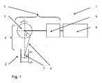
- the Fig. 1 shows a schematic diagram of a compressor unit 1, which has a reciprocating compressor 2 and a transmission unit 3.
- the gear unit 3 abreibreibitig a sliding crank 4, namely consisting of a crank 5 and a hinged connecting rod 6 as a coupling member to the thrust member. 7
- a gear stage is arranged as a gear stage 9 for the reduction of the engine speed in the transmission unit in Kraftflußraum behind the engine.
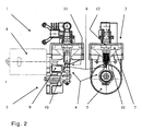
- Fig. 2 shows an embodiment of a compressor unit 1 according to the invention in two rotated by 90 ° to each other views, also equipped with a very short-built piston compressor 2 and with a gear unit 3, which on the drive side includes a sliding crank drive 4.
- the latter consists of a crank wheel 5 and a hinged connecting rod 6 as a coupling member to the thrust member designed as a piston. 7
- the fine thread connection 10 can be fixed after adjustment with the aid of a rear-mounted hexagon grub screw 11 and secure against rotation.
Landscapes
- Engineering & Computer Science (AREA)
- Mechanical Engineering (AREA)
- General Engineering & Computer Science (AREA)
- Compressor (AREA)
- Compressors, Vaccum Pumps And Other Relevant Systems (AREA)
Description
- Die Erfindung betrifft eine Kompressoreinheit, insbesondere zur Luftverdichtung innerhalb tragbarer / transportabler Geräte, welche mindestens einen Motor und einen über einen Schubkurbeltrieb angetriebenen Hubkolbenverdichter aufweist, wobei der Schubkurbeltrieb aus einem Kurbelrad und einer mit Kurbelrad und einem Kolben verbundenen Pleuelstange besteht.
- Bei solchen Kolbenverdichtern, insbesondere bei sehr einfachen und in großen Stückzahlen hergestellten Kolbenverdichtern wie etwa Kleinkompressoren zum Befüllen von Reifen, ist es wünschenswert, den Maximaldruck in bestimmten Grenzen zu halten, damit zum einen keine Materialüberlastung an den Kompressorbauteilen entsteht bzw. eine hohe Kompressorleistung und Lebensdauer bei wirtschaftlichem Materialeinsatz erreichbar ist und damit zum anderen eine Druckbefüllung ohne weitere teure Regeleinrichtungen nur bis zu einem Maximaldruck erfolgt.
- Zur Einstellung des Maximaldruckes im Arbeitsraum des Kolbenverdichters sind einige Methoden bekannt, mit denen über eine Veränderung des Todluftvolumens eine Hubraumeinstellung und damit eine Druckeinstellung vorgenommen werden kann. Als Todluftvolumen oder auch "schädliches Volumen" bezeichnet man dabei den Teil des durch Kolbenboden und Zylinderwände begrenzten Zylindervolumens, welcher nach Vollendung des Kompressionshubes noch zwischen Kolbenboden und Zylinderwand verbleibt.
- Zu diesen Methoden zählt beispielsweise die Zusammenstellung der Komponenten, nämlich Kolben, Pleuelstange, Zylinder, Zylinderkopf, mit entsprechend geeigneten Toleranzen. Dies kann jedoch nur bei ausreichend präziser Herstellung der Einzelteile erfolgreich durchgeführt werden und bleibt selbst dann ein aufwendiger Kompromiss.
- Eine weitere Methode ist das Einlegen von Zylinderkopfdichtungen unterschiedlicher Dicke, wodurch ebenfalls das Todluftvolumen beeinflusst werden kann. Dies ist aber im Grunde eine arbeitsintensive und lediglich schrittweise Annäherung an die richtigen Druckverhältnisse.
- Eine weitere Lösung sind Überdruckventile im Kolbenboden oder in den Zylinderwänden, die bei einem Maximaldruck öffnen. Abgesehen von den erforderlichen zusätzlichen Bauteilen sind bei dieser Lösung die Druckschläge und die Geräuschentwicklung gelegentlich problematisch.
- Die
DE 10 2004 015 618 A 1 offenbart einen Axialkolbenverdichter mit variablem und regelbarem Hubraum, bei dem im Wesentlichen der Druck in der Triebwerkskammer über ein oder mehrere Regelventile in Echtzeit regelbar ist. Als Triebwerkskammer oder auch "abregelndes Volumen" wird hierbei der Raum bezeichnet, in dem der Kolbenantriebsmechanismus angeordnet ist. Die Regelung erfolgt mit Hilfe eines ein oder mehrere Betriebsparameter berücksichtigenden Algorithmus und die Regelventile sind so angeordnet, das entweder die Triebwerkskammer mit der Saugseite und/oder mit der Hochdruckseite verbunden werden kann. - Hierdurch soll im Wesentlichen ein Vereisen verhindert werden, das durch zu starkes Absinken des Drucks auf der Saugseite entstehen könnte. Bei einfachen und kleinen Axialkolbenverdichtern, bei denen die Ansaugluft durch das Kolbenantriebsgehäuse des Kompressors strömt, bei denen also die Niederdruck- oder Saugseite und die Triebwerkskammer zusammenfallen, ist eine solche aufwendige Regelung nicht realisierbar.
- Zudem geht es bei den Leistungen von Kleinkompressoren weniger um die Vereisung auf der Unterdruckseite, als vielmehr darum, den Maximaldruck auf der Hochdruckseite zu begrenzen, um entweder bessere Materialauslastungen zu erreichen, oder aber um Fertigungstoleranzen für die Großserienfertigung handhabbar zu gestalten.
- Die
DE 33 33 329 A1 offenbart hierzu eine Kolbenpumpe mit den Merkmalen des Oberbegriffs von Anspruch 1, bei der zur Veränderung des Totvolumens und damit zur Minderung der Restverdichtung des Kolbenverdichters Distanzstücke zwischen Antriebsgehäuse und Pumpenteil, d.h. Zylindergehäuse eingelegt werden. Zu einer solchen Einstellung muß jedoch die gesamte Kolbenpumpe demontiert werden. - Die
US 4,479,419 offenbart einem Kompressor für Kühlflüssigkeiten mit mehreren Zylindern, bei dem der jeweilige Zylinderhub über eine exzentrische Lagerung des Pleuels auf der Kurbelwelle einstellbar ist, um unterschiedliche Volumenströme der einzelnen Zylinderpumpen zu erreichen. Eine solche Einstellung ist in der Regel aber nur einmalig bei der Herstellung möglich und verbleibt dann über die Lebensdauer des Kompressors. - Die
US 5,904,440 offenbart eine Gewindeverbindung zwischen Kolben und Kolbenstange, bei der beide Teile mit einer komplementären radialen Bohrung versehen sind, in die ein Sicherungsstift zur Sicherung gegen Verdrehen eingeführt werden kann. - Für die Erfindung bestand also die Aufgabe, die Bauart von Kompressoren so zu gestalten, dass ohne großen Aufwand eine sehr genaue Einstellung des Maximaldruckes unabhängig von Fertigungsarten und -toleranzen erfolgen kann, sodass Nacharbeit von Bauteilen vermieden wird.
- Gelöst wird diese Aufgabe durch die Merkmale des Hauptanspruchs. Vorteilhafte Weiterbildungen sind in den Unteransprüchen enthalten.
- Hierbei ist innerhalb des Schubkurbeltriebes, der aus einem Kurbelrad und einer mit Kurbelrad und mit einem Kolben verbundenen Pleuelstange besteht, eine Einrichtung zur Verstellung des Kolbenhubes angeordnet. Durch eine solche Ausbildung lässt sich während der Montage auf einfachste Weise der Kolbenhub und damit das verbleibende Todluftvolumen und der Maximaldruck bei gegebenen übrigen Abmessungen und Toleranzen einstellen.
- Eine vorteilhafte Ausbildung besteht darin, dass zwischen Kolben und Pleuelstange eine in Schubrichtung längenverstellbare Verbindung angeordnet ist.
- Durch eine solche Ausbildung lässt sich bei der Montage des Kompressors durch einfache Verkürzung oder Verlängerung des Abstandes zwischen Kolbenboden und Anlenkpunkt der Pleuelstange am Kurbelrad das verbleibende Todluftvolumen und damit der Maximaldruck bei gegebenen Toleranzen einstellen.
- Hiermit wird auch eine preiswerte Großserienherstellung der Bauteile durch formgebende Gießverfahren, wie z.B. durch ein Druckgussverfahren, ermöglicht, ohne dass die übliche umfangreiche Nacharbeit zur Einhaltung aller Toleranzen erforderlich wird.
- Eine weitere vorteilhafte Ausbildung besteht darin, dass Kolben und Pleuelstange durch eine Gewindeverbindung miteinander verbunden sind, wobei die Gewindeverbindung eine Verdrehsicherung aufweist. Damit lässt sich auf einfache Art und Weise eine Funktionstrennung in Längen-Einstellung als solche und Fixierung der Längen-Einstellung erreichen.
- Eine weitere besonders einfach und kostengünstig zur realisierende Ausbildung besteht darin, dass die Verdrehsicherung durch eine in das Gewinde eingreifende Madenschraube erfolgt, die einen rückseitigen Werkzeugansatz aufweist. Ein Nachstellen, beispielsweise nach Probeläufen, wird hier ohne weiters möglich.
- Eine besonders genaue Einstellbarkeit ergibt sich bei einer Ausbildung, bei der die Gewindeverbindung als Feingewinde ausgebildet ist.
- Eine weitere vorteilhafte Ausbildung besteht darin, dass zwischen Motor und Kolbenverdichter eine Getriebeeinheit angeordnet ist, die im Wesentlichen den Schubkurbeltrieb sowie mindestens eine Zahnradstufe als Getriebestufe aufweist. Hierdurch lassen sich insbesondere in Niederspannungssystemen Motoren mit höherer Drehzahl verwenden, die dann entsprechend untersetzt werden.
- In besonderer Weise geeignet ist ein solcher Kompressor innerhalb einer Vorrichtung zum Abdichten und Aufpumpen aufblasbarer Gegenstände, insbesondere zum Abdichten und Aufpumpen von Kraftfahrzeugreifen, wobei die Vorrichtung weiterhin einen Behälter für ein in den aufblasbaren Gegenstand einfüllbares selbsttätiges Dichtmittel, eine Ventil- und Verteilereinheit für Dichtmittel und Druckgas mit einer an den Kompressor anschließbaren Einlassleitung und einer an den aufblasbaren Gegenstand anschließbaren Auslassleitung, Verbindungsmittel zwischen Ventil- und Verteilereinheit und aufblasbarem Gegenstand, ggf. Verbindungsmittel zur Energiezufuhr sowie Schalt-, und/oder Steuer- und Anzeigeeinrichtungen für den Betrieb der Vorrichtung beinhaltet. In einer solchen Vorrichtung wird dann der Maximaldruck des Kolbenverdichters mit Hilfe der Einrichtung zur Verstellung des Kolbenhubes auf einen Wert von 6 bis 8 bar, vorzugsweise auf einen Wert von 7 bar begrenzt. Der Vorteil einer solchen Ausführung liegt darin, dass hier speziell auf ein Fahrzeug bzw. auf eine Fahrzeugreifengröße und den entsprechenden Luftdruckbereich zugeschnittene Reparatur-Sets bereitgestellt werden, die aus völlig gleichen Einzelteilen gefertigt sind und lediglich durch Veränderung ihres Maximaldruckes über einfachste Maßnahmen auf einen bestimmten Fahrzeugtyp eingestellt werden können.
- Anhand eines Ausführungsbeispieles soll die Erfindung näher erläutert werden. Es zeigen:
- Fig. 1
- eine Prinzipskizze einer erfindungsgemäßen Kompressoreinheit
- Fig. 2
- eine Ausführung einer erfindungsgemäßen Kompressoreinheit
- Die
Fig. 1 zeigt als Prinzipskizze eine Kompressoreinheit 1, welche einen Kolbenverdichter 2 aufweist sowie eine Getriebeeinheit 3. Die Getriebeeinheit 3 umfasst abtreibsseitig einen Schubkurbeltrieb 4, nämlich bestehend aus einem Kurbelrad 5 und einer angelenkten Pleuelstange 6 als Koppelglied zum Schubglied 7. - Zwischen dem als Antrieb eingesetzten Elektromotor 8 und dem Schubkurbeltrieb 4 ist in der Getriebeeinheit in Kraftflußrichtung hinter dem Motor auch eine Zahnradstufe als Getriebestufe 9 zur Untersetzung der Motordrehzahl angeordnet.
-
Fig. 2 zeigt eine Ausführung einer erfindungsgemäßen Kompressoreinheit 1 in zwei um 90° zueinander gedrehten Ansichten, ebenfalls ausgestattet mit einem sehr kurz bauendem Kolbenverdichter 2 und mit einer Getriebeeinheit 3, welche abtreibsseitig einen Schubkurbeltrieb 4 umfasst. Letzterer besteht aus einem Kurbelrad 5 und einer angelenkten Pleuelstange 6 als Koppelglied zum dem als Kolben ausgebildeten Schubglied 7. - Auch hier ist zwischen dem als Antrieb eingesetzten Elektromotor 8 und dem Schubkurbeltrieb 4 ist in Kraftflußrichtung eine Getriebestufe 9 zur Untersetzung der Motordrehzahl angeordnet.
- Mit Hilfe einer Feingewinde-Verbindung 10 ist der Kolben bzw. das Schubglied 7 mit der Pleuelstange 6 verbunden. Die Feingewinde-Verbindung 10 lässt sich nach erfolgter Einstellung mit Hilfe der einen rückseitig angebrachten Sechskant aufweisenden Madenschraube 11 festsetzen und gegen Verdrehung sichern.
- Eingestellt wird hierbei das Todluftvolumen 12, was durch den sich ergebenden Kompressionsgrad direkt dem Maximaldruck proportional ist
-
- 1
- Kompressoreinheit
- 2
- Kolbenverdichter
- 3
- Getriebeeinheit
- 4
- Schubkurbeltrieb
- 5
- Kurbelrad
- 6
- Pleuelstange
- 7
- Kolben / Schubglied
- 8
- Elektromotor
- 9
- Getriebe stufe
- 10
- Feingewinde-Verbindung
- 11
- Madenschraube
- 12
- Todluftvolumen
Claims (5)
- Kompressoreinheit (1), insbesondere zur Luftverdichtung innerhalb tragbarer /transportabler Geräte, welche mindestens einen Motor (8) und einen über einen Schubkurbeltrieb (4) angetriebenen Hubkolbenverdichter (2) aufweist, wobei der Schubkurbeltrieb aus einem Kurbelrad (5) und einer mit Kurbelrad und einem Kolben (7) verbundenen Pleuelstange (6) besteht und innerhalb des Schubkurbeltriebes eine Einrichtung zur Verstellung des Kolbenhubes angeordnet ist, dadurch gekennzeichnet, dass die Einrichtung zur Verstellung als eine in Schubrichtung längenverstellbare Gewindeverbindung (10) zwischen Kolben (7) und Pleuelstange (6) ausgebildet ist und die Gewindeverbindung eine unabhängig von der Längenverstellung wirkende Verdrehsicherung aufweist.
- Kompressoreinheit nach Anspruch 1, dadurch gekennzeichnet, die Verdrehsicherung durch eine in das Gewinde eingreifende Madenschraube (11) erfolgt, die einen rückseitigen Werkzeugansatz aufweist.
- Kompressoreinheit nach Anspruche 1 oder 2, dadurch gekennzeichnet, dass die Gewindeverbindung (10) als Feingewinde ausgebildet ist.
- Kompressoreinheit nach Anspruche 1 bis 3, dadurch gekennzeichnet, dass zwischen Motor (8) und Kolbenverdichter (2) eine Getriebeeinheit angeordnet ist, die im Wesentlichen den Schubkurbeltrieb sowie mindestens eine Zahnradstufe als Getriebestufe (9) aufweist.
- Kompressoreinheit nach den Ansprüchen 1 bis 4 zum Abdichten und Aufpumpen aufblasbarer Gegenstände, insbesondere zum Abdichten und Aufpumpen von Kraftfahrzeugreifen, wobei die Kompressoreinheit über eine eine Einlaßleitung und eine Auslaßleitung aufweisende Ventil- und Verteilereinheit für Dichtmittel und Druckgas sowohl mit einem Behälter für ein in den aufblasbaren Gegenstand einfüllbares selbsttätiges Dichtmittel verbunden ist, als auch mit einem über Verbindungsmittel zwischen Ventil- und Verteilereinheit anschließbaren und aufblasbarem Gegenstand, dadurch gekennzeichnet, dass der Maximaldruck des Kolbenverdichters (2) mit Hilfe der Einrichtung (10) zur Verstellung des Kolbenhubes auf einen Wert von 6 bis 8 bar, vorzugsweise auf einen Wert von 7 bar begrenzt wird.
Applications Claiming Priority (2)
| Application Number | Priority Date | Filing Date | Title |
|---|---|---|---|
| DE102005060320A DE102005060320A1 (de) | 2005-12-16 | 2005-12-16 | Kompressoreinheit |
| PCT/EP2006/068011 WO2007068531A1 (de) | 2005-12-16 | 2006-11-01 | Kompressoreinheit |
Publications (2)
| Publication Number | Publication Date |
|---|---|
| EP1963677A1 EP1963677A1 (de) | 2008-09-03 |
| EP1963677B1 true EP1963677B1 (de) | 2012-10-17 |
Family
ID=37670885
Family Applications (1)
| Application Number | Title | Priority Date | Filing Date |
|---|---|---|---|
| EP06807709A Not-in-force EP1963677B1 (de) | 2005-12-16 | 2006-11-01 | Kompressoreinheit |
Country Status (6)
| Country | Link |
|---|---|
| US (1) | US20080199333A1 (de) |
| EP (1) | EP1963677B1 (de) |
| JP (1) | JP4841007B2 (de) |
| CN (1) | CN101278126B (de) |
| DE (1) | DE102005060320A1 (de) |
| WO (1) | WO2007068531A1 (de) |
Families Citing this family (4)
| Publication number | Priority date | Publication date | Assignee | Title |
|---|---|---|---|---|
| DE102013107850A1 (de) * | 2013-07-23 | 2015-01-29 | Continental Reifen Deutschland Gmbh | Kompressor mit Druckbegrenzung |
| CN104047830B (zh) * | 2014-06-13 | 2016-06-22 | 江苏盈科汽车空调有限公司 | 一种可变压缩量的压缩机 |
| CN108397374B (zh) * | 2018-03-19 | 2019-06-18 | 中徽机电科技股份有限公司 | 一种空调压缩机的变容方法 |
| CN116146452B (zh) * | 2023-01-04 | 2026-01-06 | 何友方 | 一种用于低空飞行器的高压喷气装置及其喷气发动机 |
Family Cites Families (23)
| Publication number | Priority date | Publication date | Assignee | Title |
|---|---|---|---|---|
| US302309A (en) * | 1884-07-22 | Gas-engine pump | ||
| US2771846A (en) * | 1954-05-17 | 1956-11-27 | John Blue Company Inc | Variable-capacity metering pump |
| US2907614A (en) * | 1958-02-25 | 1959-10-06 | Rosen Sidney | Precision pump |
| US3169674A (en) * | 1962-04-05 | 1965-02-16 | Lund Jens | Pump with delivery adjustment |
| US3815480A (en) * | 1969-11-17 | 1974-06-11 | R Spyra | Variable stroke cylinder |
| US3927605A (en) * | 1974-02-25 | 1975-12-23 | Graco Inc | Linkage-drive pump |
| US4479419A (en) * | 1982-11-02 | 1984-10-30 | Westinghouse Electric Corp. | Dual capacity reciprocating compressor |
| DE3333329A1 (de) * | 1983-09-15 | 1985-03-28 | Becker, Erich, 7812 Bad Krozingen | Kolbenpumpe, insbesondere pendelkolbenpumpe |
| JPH0639912B2 (ja) * | 1983-12-29 | 1994-05-25 | 本田技研工業株式会社 | 車両用内燃機関における圧縮比可変制御装置 |
| DE3666092D1 (en) * | 1985-08-19 | 1989-11-09 | Ralph Gordon Morgado | Variable volume apparatus |
| DE3544016A1 (de) * | 1985-12-13 | 1987-06-19 | Kopperschmidt Mueller & Co | Pumpenanordnung zur dosierten abgabe von mindestens zwei komponenten |
| DE4134063A1 (de) * | 1991-10-15 | 1993-04-22 | Festo Kg | Linearantrieb |
| JPH06212993A (ja) * | 1993-01-18 | 1994-08-02 | Mitsubishi Motors Corp | エンジンの可変圧縮比装置 |
| DE4429097A1 (de) * | 1994-08-17 | 1996-02-22 | Thurner Bayer Druckguss | Kolbenverdichter für gasförmige Medien |
| DE19549592C5 (de) * | 1995-07-11 | 2006-12-14 | Sumitomo Rubber Industries Ltd., Kobe | Vorrichtung zum Abdichten und Aufpumpen von Reifen bei Pannen |
| US5904440A (en) * | 1997-07-18 | 1999-05-18 | Sims; James O. | Piston/piston rod assembly having positive locking means between said piston and said piston rod |
| DE19849785C1 (de) * | 1998-10-28 | 2000-03-16 | Ott Kg Lewa | Verfahren und Vorrichtung zur Förderstromeinstellung bei oszillierenden Verdrängerpumpen |
| US6341946B1 (en) * | 1999-06-14 | 2002-01-29 | International Business Machines Corporation | Continuously adjustable telescopic pedal crank length |
| KR100379478B1 (ko) * | 2000-10-13 | 2003-04-10 | 엘지전자 주식회사 | 왕복동형 압축기 |
| JP2005207391A (ja) * | 2004-01-26 | 2005-08-04 | Toyota Motor Corp | 内燃機関 |
| TWI235790B (en) * | 2004-02-29 | 2005-07-11 | Wen-Shan Chou | Miniature simple air filling device |
| DE102004015618A1 (de) * | 2004-03-30 | 2005-10-20 | Zexel Valeo Compressor Europe | Hubraumvariabler Verdichter sowie Verfahren zur Regelung des Kolbenhubs in einem solchen |
| JP4392292B2 (ja) * | 2004-06-01 | 2009-12-24 | 住友ゴム工業株式会社 | 小型簡易コンプレッサ装置 |
-
2005
- 2005-12-16 DE DE102005060320A patent/DE102005060320A1/de not_active Withdrawn
-
2006
- 2006-11-01 JP JP2008537120A patent/JP4841007B2/ja not_active Expired - Fee Related
- 2006-11-01 CN CN2006800348117A patent/CN101278126B/zh not_active Expired - Fee Related
- 2006-11-01 WO PCT/EP2006/068011 patent/WO2007068531A1/de not_active Ceased
- 2006-11-01 EP EP06807709A patent/EP1963677B1/de not_active Not-in-force
-
2008
- 2008-04-25 US US12/109,773 patent/US20080199333A1/en not_active Abandoned
Also Published As
| Publication number | Publication date |
|---|---|
| JP4841007B2 (ja) | 2011-12-21 |
| EP1963677A1 (de) | 2008-09-03 |
| DE102005060320A1 (de) | 2007-06-21 |
| CN101278126B (zh) | 2013-06-05 |
| WO2007068531A1 (de) | 2007-06-21 |
| US20080199333A1 (en) | 2008-08-21 |
| JP2009512817A (ja) | 2009-03-26 |
| CN101278126A (zh) | 2008-10-01 |
Similar Documents
| Publication | Publication Date | Title |
|---|---|---|
| DE4229069C2 (de) | Taumelscheiben-Kältemittelkompressor für ein Kühlsystem | |
| EP0702755A1 (de) | Mehrstufenregler für schmiermittelpumpen mit kontinuierlich veränderbarem fördervolumen | |
| EP3482076B1 (de) | Zylinderkopfdeckel für einen kältemittelkompressor | |
| DE602004001699T2 (de) | Schraubenverdichter mit manuell einstellbarem innerem Mengenverhältnis und Fördermenge | |
| DE19530210C2 (de) | Taumelscheibenverdichter | |
| EP1963677B1 (de) | Kompressoreinheit | |
| EP0925445A1 (de) | Radialkolbenpumpe zur kraftstoffhochdruckversorgung | |
| DE4042242C2 (de) | Kompressor | |
| EP2357115B1 (de) | Druckluftkompressor und Verfahren zum Betrieb eines Druckluftkompressors | |
| WO2004005712A1 (de) | Hubkolbenmaschine | |
| DE717647C (de) | Hilfspumpensatz fuer Zweitaktbrennkraftmaschinen | |
| DE10306031A1 (de) | Kompressor | |
| DE4428410C2 (de) | Kompakte Regeleinheit für eine Flügelzellenpumpe | |
| DE102015210597A1 (de) | Hubkolbenmotor und Kraftfahrzeug | |
| EP1211419A2 (de) | Vorrichtung zum Fördern von Flüssigkeiten, insbesondere Kraftstoff | |
| DE102004019626B4 (de) | Kraftstoffeinspritzpumpe und Dreh-/Linearbewegungsumwandlungsmechanismus mit Sicherungseinrichtung | |
| DE69400055T2 (de) | Kolbenpumpe | |
| WO2022238150A1 (de) | Radialkolbenpumpe, sowie verfahren zur herstellung einer radialkolbenpumpe | |
| WO2009010039A2 (de) | Vorrichtung zur stufenlosen regulierung des schadraumvolumens eines kolbenverdichters | |
| DE69313120T2 (de) | Mit einem lader und einem kraffstoffeinspritzsystem versehene brennkraftmaschinenanlage | |
| WO2015091169A1 (de) | Kompressorsystem mit einer kolbenhubeinstellvorrichtung | |
| EP1922486A1 (de) | Verfahren zur montage eines kurbeltriebs und kolbenverdichter | |
| WO2001036820A9 (de) | Hydraulische kolbenpumpe | |
| DE3820632C2 (de) | ||
| DE3609586A1 (de) | Fluessigkraftstoff - pumpvorrichtung |
Legal Events
| Date | Code | Title | Description |
|---|---|---|---|
| PUAI | Public reference made under article 153(3) epc to a published international application that has entered the european phase |
Free format text: ORIGINAL CODE: 0009012 |
|
| 17P | Request for examination filed |
Effective date: 20080716 |
|
| AK | Designated contracting states |
Kind code of ref document: A1 Designated state(s): AT BE BG CH CY CZ DE DK EE ES FI FR GB GR HU IE IS IT LI LT LU LV MC NL PL PT RO SE SI SK TR |
|
| 17Q | First examination report despatched |
Effective date: 20081112 |
|
| RAP1 | Party data changed (applicant data changed or rights of an application transferred) |
Owner name: CONTINENTAL REIFEN DEUTSCHLAND GMBH |
|
| GRAP | Despatch of communication of intention to grant a patent |
Free format text: ORIGINAL CODE: EPIDOSNIGR1 |
|
| DAX | Request for extension of the european patent (deleted) | ||
| GRAS | Grant fee paid |
Free format text: ORIGINAL CODE: EPIDOSNIGR3 |
|
| GRAA | (expected) grant |
Free format text: ORIGINAL CODE: 0009210 |
|
| AK | Designated contracting states |
Kind code of ref document: B1 Designated state(s): AT BE BG CH CY CZ DE DK EE ES FI FR GB GR HU IE IS IT LI LT LU LV MC NL PL PT RO SE SI SK TR |
|
| REG | Reference to a national code |
Ref country code: GB Ref legal event code: FG4D Free format text: NOT ENGLISH |
|
| REG | Reference to a national code |
Ref country code: CH Ref legal event code: EP |
|
| REG | Reference to a national code |
Ref country code: IE Ref legal event code: FG4D Free format text: LANGUAGE OF EP DOCUMENT: GERMAN |
|
| REG | Reference to a national code |
Ref country code: AT Ref legal event code: REF Ref document number: 580032 Country of ref document: AT Kind code of ref document: T Effective date: 20121115 |
|
| REG | Reference to a national code |
Ref country code: DE Ref legal event code: R096 Ref document number: 502006012109 Country of ref document: DE Effective date: 20121213 |
|
| REG | Reference to a national code |
Ref country code: NL Ref legal event code: VDEP Effective date: 20121017 |
|
| REG | Reference to a national code |
Ref country code: LT Ref legal event code: MG4D |
|
| PG25 | Lapsed in a contracting state [announced via postgrant information from national office to epo] |
Ref country code: FI Free format text: LAPSE BECAUSE OF FAILURE TO SUBMIT A TRANSLATION OF THE DESCRIPTION OR TO PAY THE FEE WITHIN THE PRESCRIBED TIME-LIMIT Effective date: 20121017 Ref country code: NL Free format text: LAPSE BECAUSE OF FAILURE TO SUBMIT A TRANSLATION OF THE DESCRIPTION OR TO PAY THE FEE WITHIN THE PRESCRIBED TIME-LIMIT Effective date: 20121017 Ref country code: IS Free format text: LAPSE BECAUSE OF FAILURE TO SUBMIT A TRANSLATION OF THE DESCRIPTION OR TO PAY THE FEE WITHIN THE PRESCRIBED TIME-LIMIT Effective date: 20130217 Ref country code: ES Free format text: LAPSE BECAUSE OF FAILURE TO SUBMIT A TRANSLATION OF THE DESCRIPTION OR TO PAY THE FEE WITHIN THE PRESCRIBED TIME-LIMIT Effective date: 20130128 Ref country code: LT Free format text: LAPSE BECAUSE OF FAILURE TO SUBMIT A TRANSLATION OF THE DESCRIPTION OR TO PAY THE FEE WITHIN THE PRESCRIBED TIME-LIMIT Effective date: 20121017 Ref country code: SE Free format text: LAPSE BECAUSE OF FAILURE TO SUBMIT A TRANSLATION OF THE DESCRIPTION OR TO PAY THE FEE WITHIN THE PRESCRIBED TIME-LIMIT Effective date: 20121017 |
|
| BERE | Be: lapsed |
Owner name: CONTINENTAL REIFEN DEUTSCHLAND G.M.B.H. Effective date: 20121130 |
|
| PG25 | Lapsed in a contracting state [announced via postgrant information from national office to epo] |
Ref country code: PT Free format text: LAPSE BECAUSE OF FAILURE TO SUBMIT A TRANSLATION OF THE DESCRIPTION OR TO PAY THE FEE WITHIN THE PRESCRIBED TIME-LIMIT Effective date: 20130218 Ref country code: GR Free format text: LAPSE BECAUSE OF FAILURE TO SUBMIT A TRANSLATION OF THE DESCRIPTION OR TO PAY THE FEE WITHIN THE PRESCRIBED TIME-LIMIT Effective date: 20130118 Ref country code: PL Free format text: LAPSE BECAUSE OF FAILURE TO SUBMIT A TRANSLATION OF THE DESCRIPTION OR TO PAY THE FEE WITHIN THE PRESCRIBED TIME-LIMIT Effective date: 20121017 Ref country code: SI Free format text: LAPSE BECAUSE OF FAILURE TO SUBMIT A TRANSLATION OF THE DESCRIPTION OR TO PAY THE FEE WITHIN THE PRESCRIBED TIME-LIMIT Effective date: 20121017 Ref country code: LV Free format text: LAPSE BECAUSE OF FAILURE TO SUBMIT A TRANSLATION OF THE DESCRIPTION OR TO PAY THE FEE WITHIN THE PRESCRIBED TIME-LIMIT Effective date: 20121017 Ref country code: CY Free format text: LAPSE BECAUSE OF FAILURE TO SUBMIT A TRANSLATION OF THE DESCRIPTION OR TO PAY THE FEE WITHIN THE PRESCRIBED TIME-LIMIT Effective date: 20121017 |
|
| REG | Reference to a national code |
Ref country code: CH Ref legal event code: PL |
|
| PG25 | Lapsed in a contracting state [announced via postgrant information from national office to epo] |
Ref country code: CZ Free format text: LAPSE BECAUSE OF FAILURE TO SUBMIT A TRANSLATION OF THE DESCRIPTION OR TO PAY THE FEE WITHIN THE PRESCRIBED TIME-LIMIT Effective date: 20121017 Ref country code: DK Free format text: LAPSE BECAUSE OF FAILURE TO SUBMIT A TRANSLATION OF THE DESCRIPTION OR TO PAY THE FEE WITHIN THE PRESCRIBED TIME-LIMIT Effective date: 20121017 Ref country code: EE Free format text: LAPSE BECAUSE OF FAILURE TO SUBMIT A TRANSLATION OF THE DESCRIPTION OR TO PAY THE FEE WITHIN THE PRESCRIBED TIME-LIMIT Effective date: 20121017 Ref country code: CH Free format text: LAPSE BECAUSE OF NON-PAYMENT OF DUE FEES Effective date: 20121130 Ref country code: SK Free format text: LAPSE BECAUSE OF FAILURE TO SUBMIT A TRANSLATION OF THE DESCRIPTION OR TO PAY THE FEE WITHIN THE PRESCRIBED TIME-LIMIT Effective date: 20121017 Ref country code: LI Free format text: LAPSE BECAUSE OF NON-PAYMENT OF DUE FEES Effective date: 20121130 Ref country code: BG Free format text: LAPSE BECAUSE OF FAILURE TO SUBMIT A TRANSLATION OF THE DESCRIPTION OR TO PAY THE FEE WITHIN THE PRESCRIBED TIME-LIMIT Effective date: 20130117 |
|
| REG | Reference to a national code |
Ref country code: IE Ref legal event code: MM4A |
|
| PLBE | No opposition filed within time limit |
Free format text: ORIGINAL CODE: 0009261 |
|
| STAA | Information on the status of an ep patent application or granted ep patent |
Free format text: STATUS: NO OPPOSITION FILED WITHIN TIME LIMIT |
|
| PG25 | Lapsed in a contracting state [announced via postgrant information from national office to epo] |
Ref country code: RO Free format text: LAPSE BECAUSE OF FAILURE TO SUBMIT A TRANSLATION OF THE DESCRIPTION OR TO PAY THE FEE WITHIN THE PRESCRIBED TIME-LIMIT Effective date: 20121017 Ref country code: BE Free format text: LAPSE BECAUSE OF NON-PAYMENT OF DUE FEES Effective date: 20121130 |
|
| 26N | No opposition filed |
Effective date: 20130718 |
|
| PG25 | Lapsed in a contracting state [announced via postgrant information from national office to epo] |
Ref country code: IE Free format text: LAPSE BECAUSE OF NON-PAYMENT OF DUE FEES Effective date: 20121101 |
|
| REG | Reference to a national code |
Ref country code: DE Ref legal event code: R097 Ref document number: 502006012109 Country of ref document: DE Effective date: 20130718 |
|
| REG | Reference to a national code |
Ref country code: AT Ref legal event code: MM01 Ref document number: 580032 Country of ref document: AT Kind code of ref document: T Effective date: 20121130 |
|
| PG25 | Lapsed in a contracting state [announced via postgrant information from national office to epo] |
Ref country code: AT Free format text: LAPSE BECAUSE OF NON-PAYMENT OF DUE FEES Effective date: 20121130 |
|
| PG25 | Lapsed in a contracting state [announced via postgrant information from national office to epo] |
Ref country code: TR Free format text: LAPSE BECAUSE OF FAILURE TO SUBMIT A TRANSLATION OF THE DESCRIPTION OR TO PAY THE FEE WITHIN THE PRESCRIBED TIME-LIMIT Effective date: 20121017 Ref country code: MC Free format text: LAPSE BECAUSE OF NON-PAYMENT OF DUE FEES Effective date: 20121130 |
|
| PG25 | Lapsed in a contracting state [announced via postgrant information from national office to epo] |
Ref country code: LU Free format text: LAPSE BECAUSE OF NON-PAYMENT OF DUE FEES Effective date: 20121101 |
|
| PG25 | Lapsed in a contracting state [announced via postgrant information from national office to epo] |
Ref country code: HU Free format text: LAPSE BECAUSE OF FAILURE TO SUBMIT A TRANSLATION OF THE DESCRIPTION OR TO PAY THE FEE WITHIN THE PRESCRIBED TIME-LIMIT Effective date: 20061101 |
|
| REG | Reference to a national code |
Ref country code: FR Ref legal event code: PLFP Year of fee payment: 10 |
|
| REG | Reference to a national code |
Ref country code: FR Ref legal event code: PLFP Year of fee payment: 11 |
|
| REG | Reference to a national code |
Ref country code: FR Ref legal event code: PLFP Year of fee payment: 12 |
|
| PGFP | Annual fee paid to national office [announced via postgrant information from national office to epo] |
Ref country code: DE Payment date: 20191130 Year of fee payment: 14 |
|
| PGFP | Annual fee paid to national office [announced via postgrant information from national office to epo] |
Ref country code: FR Payment date: 20191120 Year of fee payment: 14 Ref country code: IT Payment date: 20191128 Year of fee payment: 14 |
|
| PGFP | Annual fee paid to national office [announced via postgrant information from national office to epo] |
Ref country code: GB Payment date: 20191120 Year of fee payment: 14 |
|
| REG | Reference to a national code |
Ref country code: DE Ref legal event code: R119 Ref document number: 502006012109 Country of ref document: DE |
|
| GBPC | Gb: european patent ceased through non-payment of renewal fee |
Effective date: 20201101 |
|
| PG25 | Lapsed in a contracting state [announced via postgrant information from national office to epo] |
Ref country code: FR Free format text: LAPSE BECAUSE OF NON-PAYMENT OF DUE FEES Effective date: 20201130 Ref country code: IT Free format text: LAPSE BECAUSE OF NON-PAYMENT OF DUE FEES Effective date: 20201101 |
|
| PG25 | Lapsed in a contracting state [announced via postgrant information from national office to epo] |
Ref country code: GB Free format text: LAPSE BECAUSE OF NON-PAYMENT OF DUE FEES Effective date: 20201101 Ref country code: DE Free format text: LAPSE BECAUSE OF NON-PAYMENT OF DUE FEES Effective date: 20210601 |