EP1963704B1 - Générateur de force - Google Patents
Générateur de force Download PDFInfo
- Publication number
- EP1963704B1 EP1963704B1 EP06818959A EP06818959A EP1963704B1 EP 1963704 B1 EP1963704 B1 EP 1963704B1 EP 06818959 A EP06818959 A EP 06818959A EP 06818959 A EP06818959 A EP 06818959A EP 1963704 B1 EP1963704 B1 EP 1963704B1
- Authority
- EP
- European Patent Office
- Prior art keywords
- transducer
- force generator
- inertial mass
- flexural arm
- arm
- Prior art date
- Legal status (The legal status is an assumption and is not a legal conclusion. Google has not performed a legal analysis and makes no representation as to the accuracy of the status listed.)
- Ceased
Links
Images

Classifications
-
- F—MECHANICAL ENGINEERING; LIGHTING; HEATING; WEAPONS; BLASTING
- F16—ENGINEERING ELEMENTS AND UNITS; GENERAL MEASURES FOR PRODUCING AND MAINTAINING EFFECTIVE FUNCTIONING OF MACHINES OR INSTALLATIONS; THERMAL INSULATION IN GENERAL
- F16F—SPRINGS; SHOCK-ABSORBERS; MEANS FOR DAMPING VIBRATION
- F16F7/00—Vibration-dampers; Shock-absorbers
- F16F7/10—Vibration-dampers; Shock-absorbers using inertia effect
- F16F7/1005—Vibration-dampers; Shock-absorbers using inertia effect characterised by active control of the mass
- F16F7/1011—Vibration-dampers; Shock-absorbers using inertia effect characterised by active control of the mass by electromagnetic means
-
- B—PERFORMING OPERATIONS; TRANSPORTING
- B06—GENERATING OR TRANSMITTING MECHANICAL VIBRATIONS IN GENERAL
- B06B—METHODS OR APPARATUS FOR GENERATING OR TRANSMITTING MECHANICAL VIBRATIONS OF INFRASONIC, SONIC, OR ULTRASONIC FREQUENCY, e.g. FOR PERFORMING MECHANICAL WORK IN GENERAL
- B06B1/00—Methods or apparatus for generating mechanical vibrations of infrasonic, sonic, or ultrasonic frequency
- B06B1/02—Methods or apparatus for generating mechanical vibrations of infrasonic, sonic, or ultrasonic frequency making use of electrical energy
- B06B1/06—Methods or apparatus for generating mechanical vibrations of infrasonic, sonic, or ultrasonic frequency making use of electrical energy operating with piezoelectric effect or with electrostriction
-
- F—MECHANICAL ENGINEERING; LIGHTING; HEATING; WEAPONS; BLASTING
- F16—ENGINEERING ELEMENTS AND UNITS; GENERAL MEASURES FOR PRODUCING AND MAINTAINING EFFECTIVE FUNCTIONING OF MACHINES OR INSTALLATIONS; THERMAL INSULATION IN GENERAL
- F16F—SPRINGS; SHOCK-ABSORBERS; MEANS FOR DAMPING VIBRATION
- F16F15/00—Suppression of vibrations in systems; Means or arrangements for avoiding or reducing out-of-balance forces, e.g. due to motion
- F16F15/28—Counterweights, i.e. additional weights counterbalancing inertia forces induced by the reciprocating movement of masses in the system, e.g. of pistons attached to an engine crankshaft; Attaching or mounting same
-
- H—ELECTRICITY
- H10—SEMICONDUCTOR DEVICES; ELECTRIC SOLID-STATE DEVICES NOT OTHERWISE PROVIDED FOR
- H10N—ELECTRIC SOLID-STATE DEVICES NOT OTHERWISE PROVIDED FOR
- H10N30/00—Piezoelectric or electrostrictive devices
- H10N30/20—Piezoelectric or electrostrictive devices with electrical input and mechanical output, e.g. functioning as actuators or vibrators
Definitions
- the invention relates to a power generator and a method for operating the power generator.
- the force generator is used in particular for influencing the vibration of structures, with targeted counter-vibrations being introduced into a structure in order to reduce the overall level of the vibrations in the structure.
- the invention relates to a device for vibration control. The invention finds particular application in vibration control in helicopters and aircraft.
- Power generators serve to generate a desired force by means of a predetermined inertial mass.
- the force always results from the inertia of the inertial mass, however it is moved.
- the inertial mass can be moved with the highest possible acceleration (or high deflection). Alternatively or additionally, such a high force can also be generated by the highest possible inertial mass.
- Such power generators are used, for example, for the targeted introduction of forces into oscillating structures (eg aircraft, motor vehicles or motor vehicles) Machine components) to counteract and cancel high vibration levels.
- oscillating structures eg aircraft, motor vehicles or motor vehicles
- problems arise when the frequency of the structure to be controlled varies more or less strongly, as is the case, for example, in the case of different operating states of the oscillating structure.
- Such different operating conditions occur, for example, in aircraft in the different phases of flight, especially at take-off and landing.
- vibration can usually be reduced only in a very narrow frequency range, which is disadvantageous in many applications.
- JP 7 168631 A discloses a force generator adapted for attachment to a structure for controllably inducing vibration forces thereon to vibrate the structure with a flex arm attached to the structure at one end and an inertial mass coupled to the flex arm remote from the attachment end of the flex arm is.
- JP 10322424 discloses a piezoelectric element which is attached to front and rear sides of an elastic plate and a mass which is fixed to one end of the elastic plate.
- EP 0 907 036 A2 discloses a mechanical resonator with a spring which is tensioned on at least one side and an attached mass, which are connected in each case or together with an electromechanical converter and a movement and / or acceleration sensor, the movement and / or acceleration of the spring and / or the mass detected.
- JP 1257900 A discloses polarized piezoelectric plates mounted on upper and opposite surfaces of a rectangular metallic plate. Electrodes are formed on the surfaces and weights are attached to two open ends of the metallic plate.
- An object of the invention is to provide a force generator which generates high accelerations and thus forces at a given inertial mass and at the same time has a favorable ratio of inertial mass and thus generated force.
- the inventive force generator should also have a high quality, i. have low internal damping and low energy consumption.
- Another object is to provide a power generator that is universally and variably applicable; that is, with which in particular vibrations over a wide frequency range as possible can be effectively reduced. It is a further object to provide a method by which such a power generator can be operated.
- the force generator according to the invention is designed for attachment to a structure for controllably introducing vibration forces for influencing the structure of the structure, and comprises a bending arm which can be fastened to the structure at at least one end thereof, as well as an inertial mass which is remote from the attachment end of the bending arm coupled to the bending arm.
- the bending arm is provided with an electromechanical transducer, and a drive for the electromechanical transducer is provided, which is arranged, by driving the electromechanical transducer to bend the bending arm with the inertial mass and the transducer and thereby deflect the inertial mass that vibrational forces of variable amplitude, phase and frequency can be generated in the structure, which can be introduced via the attachment end in the structure.
- the control set up to put the inertial mass, the bending arm and the electromechanical transducer in a vibration with adjustable amplitude, phase and frequency can be generated and introduced into a structure to be influenced.
- the phase as well as the frequency is variably adjustable.
- electromechanical transducer can also be controlled in such a way that it is simultaneously possible to introduce vibrational forces at two or more frequencies.
- the control takes place at several frequencies or over a predetermined frequency range.
- the dynamic increase in the deflection of the inertial mass for generating particularly high forces can advantageously be utilized. Due to the excitation in the region of the natural frequency, a high oscillation amplitude of the inertial mass can be achieved with a predetermined inertial mass. This is accompanied by a high acceleration, so that relatively high forces can be generated by the inertial mass. Conveniently, the inertial mass is a multiple of the mass of the bending arm including transducer, so that the power generator has a relatively low total mass and achieves high efficiency.
- the transducer is a piezoelectric actuator.
- Such an actuator has a very fast response and is precisely adjustable both in terms of Stellwegamplituden and its frequencies. This can be set for the power generator exactly predetermined exciter frequencies.
- a piezoelectric actuator works even with high counter forces with high travel ranges and high resolution, so that even with a large inertial mass vibration forces can be generated.
- the piezoelectric actuator is a stacked piezoelectric element (i.e., a so-called "piezostack") with a d33 effect.
- the d33 effect which is also known as the longitudinal effect
- the change in length of the piezoelectric element takes place in the direction of the applied electric field, i. along the stacking or longitudinal direction of the piezoelectric element.
- the resulting change in length is known to be greater than the change in length in the d31 effect, in which the change in length is transverse to the direction of the applied electric field.
- the transducer is controllable so that it performs a change in length in the longitudinal direction of the bending arm. This leads to a bending of the bending arm, which in turn deflects the inertial mass, so that vibrations of the bending arm with the inertial mass and the transducer are triggered in order to generate corresponding vibrational forces. If the transducer is arranged parallel to a neutral position, which extends along the center line of the bending arm in the case of a symmetrically constructed bending arm, then a position parallel to the neutral position can be changed in length compared to the neutral position. The larger length layer induces a deflection toward the shorter length layer. If the change in length is repeated at periodic intervals, a bending vibration of the bending arm including transducer and inertial mass is created. When excitation in the natural frequency range, the system oscillates to large amplitudes.
- At least one transducer is arranged on opposite sides of the neutral position, so that a deflection is produced towards both opposite sides of the neutral position, whereby advantageously the deflection of the inertial mass can be increased.
- the converter with the neutral position is positively and / or positively connected.
- On the other hand is achieved by the positioning of the transducer in the vicinity of the neutral position that at very high vibration amplitudes of the transducer is bent relatively little. This is a measure to protect the transducer from mechanical deformation by bending. The protection can be increased if the at least one transducer is arranged within or embedded in the bending arm. Damage to a mechanically sensitive transducer from outside is therefore only possible with difficulty.
- encapsulation of the transducer can be achieved so that the force generator is also e.g. usable in wet or chemically aggressive environment.
- a spacer element is arranged between one end of the transducer and the inertial mass. Due to the spacer element, the converter can be positioned even more securely in its position.
- the spacer element has a low density to increase the ratio of inertial mass to the mass of the bending arm including transducers.
- the natural frequency of the assembly of bending arm, transducer and inertial mass are selectively influenced.
- a protective outer layer of the bending arm which is arranged laterally spaced from the neutral position, connected to the transducer non-positively and / or positively.
- the bending arm is formed in fiber composite construction with integrated transducer.
- the bending arm is thereby produced in layer construction using fiber composite materials, in particular glass fiber reinforced plastic (GRP), wherein the layer structure infiltrated or cured in a last step, for example by means of known RTM ("Resin Transfer Molding") method with a resin system and then cured becomes.
- GRP glass fiber reinforced plastic
- the transducer is under a compressive bias.
- This ensures that the transducer always at a high vibration amplitude (eg resonance peaking) of the bending arm pressure forces and no dangerous for the transducer tensile forces act.
- This is particularly important in a transducer having piezoceramic layers.
- the pressure-biased transducer can withstand high vibration amplitudes better.
- the compressive prestressing can be mechanically impressed.
- the transducer can also be thermally biased. This can be achieved, for example, by inserting it into a matrix which has a different thermal expansion coefficient than the transducer. Upon thermosetting of the matrix, a compressive bias may then be applied to the transducer be achieved. Another possibility is to apply an electrical offset voltage to the converter.
- the transducer is always subjected to compression and protected even at high vibration amplitudes from a tensile load.
- the force generator according to the invention typically has a length of 3 to 60 centimeters.
- the inertial mass is then displaceable, for example, with suitable dimensioning of all components in a vibration having a maximum amplitude of vibration in the range of 0.1 to 3 centimeters.
- the object is also achieved by a method for operating the force generator as described above, wherein by suitable control of the electromechanical transducer of the bending arm with the inertial mass and the transducer is bent and thereby the inertial mass is deflected that vibrational forces with variable amplitude, phase and frequency be generated.
- the object of the invention is also achieved by a device for influencing vibration, which is designed for attachment to at least one structure to controllably initiate vibrational forces in the structure, wherein two power generators of the type described above are arranged such that the bending arm of the first power generator in extension the bending arm of the second power generator is arranged.
- the force generator according to the invention can also be used in a symmetrical design, wherein two individual force generators n described type are used such that each not coupled to the inertial mass ends of the bending arms are attached to a structure to be vibrationally influenced or connected to each other, the they form a bending arm with both sides, ie at both ends of a bending arm, arranged inertial masses.
- the inertial masses should have the same propriety to the structure, ie the lever arms of the bending arms are preferably identical.
- the arrangement can be controlled so that the inertial masses are deflected parallel, ie in the same direction, or anti-parallel, ie in opposite directions. In the latter case not only forces but also moments can be introduced into the structure.
- a bending arm of a first power generator is extended quasi over the inertial mass out, and the free end of the extended bending arm also attached to the structure, but elsewhere is.
- a bending arm is provided, whose opposite ends can be fastened to a structure, wherein at least one inertial mass is preferably provided in the middle of the bending arm. In such an arrangement, the introduction of forces takes place torque-free.
- the force generator according to the invention and its symmetrical use are used in particular for active vibration control of structures (aircraft, motor vehicles, machine components, etc.).
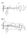
- Fig. 1 is a schematic representation of a power generator 1 is shown. It has a bending arm 2, which is fastened at one end to a structure 3 and has an inertial mass 4 at the other end.
- the structure 3 is for example an aircraft, a motor vehicle, a machine component or any other component, wherein the structure 3 oscillates in an undesired manner.
- the force generator 1 is connected to the structure 3, so that counter-vibrations can be introduced into the structure 3 in a targeted manner in order to reduce the overall level of the vibrations in the structure 3, as will be explained in more detail below.
- an electromechanical transducer 5 is mounted, in particular a piezoelectric actuator, with a drive. 6 electrically connected.
- the position of the drive 6 is arranged by the bending arm 2 and the transducer 5 at such a distance that it does not hinder movement of the bending arm 2, including transducer 5 and inertial mass 4.
- the bending arm 2 is located together with the inertial mass 4 and the electromechanical transducer 5 in the in Fig.1 shown position in a rest position, wherein the center line 7 of the bending arm 2 extends horizontally.
- the electromechanical transducer 5 is controlled such that it undergoes a positive change in length .DELTA.l in the longitudinal direction of the bending arm 2.
- the transducer 5 is connected to the upper edge fiber 8 of the bending arm 2 so that the change in length .DELTA.l of the transducer 5 is transmitted to the upper edge fiber 8, so that their length I extended by .DELTA.l. Since no change in length is exerted on the lower edge fiber 9, this results in a length difference of ⁇ l between the upper edge fiber 8 and the lower edge fiber 9. How out Fig. 2 can be seen, this length difference .DELTA.l leads to a bending of the bending arm 2 in the negative y-direction.
- the rigidly connected to the bending arm 2 inertial mass 4 is thereby shifted from its rest position shown by a dashed line in a solid line shown bent position by the amount ⁇ y .
- the increase in length by .DELTA.l of the upper edge fiber 8 thus changes the center line 7 of the bending arm 2 their horizontal course in the dashed line 12 shown bent position.
- the transducer 5 follows the curvature of the upper edge fiber.
- the bending arm 2 including the transducer 5 and the inertial mass 4 can be excited to vibrate, in which the inertial mass 4 and the bending arm 2 with the transducer 5 oscillate up and down about the horizontal line 7 extending in the horizontal direction as indicated by arrow 11 in Fig. 1 is indicated.
- suitable control eg U ( ⁇ ) or U ( ⁇ )
- the amplitude, phase and frequency of the oscillation by suitable control (eg U ( ⁇ ) or U ( ⁇ )) of the transducer 5 are adjustable so that on the attachment point 10 in the structure 3 targeted vibration forces can be introduced to overlap induced and structure oscillations a reduction, ideally extinction, the vibrations over a wide frequency range and / or at several frequencies simultaneously to effect.
- at least one sensor (not shown) is provided which detects the vibrations of the structure 3 in order to control the control 6 based on the detected sensor signals.
- the inertial mass 4 can be deflected by an amount in the y-direction which is due to resonance increase is several times higher than the amount Ay. Due to the higher oscillation amplitude, the inertial mass 4 experiences a greater acceleration, so that substantially larger forces or higher oscillation amplitudes are generated.
- the electromechanical transducer 5 is preferably a stacked piezoelectric element with d33 effect.
- the stacking direction extends essentially in the longitudinal direction of the bending arm 2, ie in the horizontal direction, in order to bring about the length change ⁇ l described above in the longitudinal direction of the bending arm 2.
- the transducer 5 is non-positively connected to the bending arm 2, for example by gluing.
- a recess (not shown) may be provided, in which the transducer 5 is fitted such that a horizontal displacement or slippage of the transducer 5 is not possible.
- the arrangement of bending arm 2 and transducer 5 can additionally be provided with a protective layer (not shown) or embedded in a fiber composite arrangement, the latter being described in connection with the description of FIG Fig. 7 will be explained in more detail.
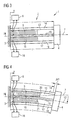
- a first embodiment of the power generator according to the invention is shown.
- the bending arm 2 is constructed in layered construction. It has a neutral position 19 which runs along the center line 7 of the bending arm 2.
- the bending arm 2 has an upper outer layer 14 and a lower outer layer 18.
- a first actuator as an electromechanical transducer 5 and an additional element 13 are arranged, which is also referred to below as a spacer element, the distance between the actuator 5 and inertial mass 4 and the distance between the neutral position 19 and the upper outer layer 14 fills up.
- a second actuator 15 and a distance element adjacent thereto 17 is located between the neutral position 19 and the lower outer layer 18, a second actuator 15 and a distance element adjacent thereto 17.
- the first actuator 5 is coupled to a control 6 and the second actuator 15 with a control 16, each depending on Sensor signals, which are recorded by corresponding sensors (not shown) for detecting the vibration of the structure (3) are controlled.
- the control signals for the drives 6, 16 may be identical or different (eg, U ( ⁇ 1 ) and U ( ⁇ 2 )), each individual transducer 5, 15 can be stimulated simultaneously at several frequencies.
- the transducers 5, 15 in turn as piezoelectric actuators, in particular as stacked piezoelectric elements with d33 effect formed.
- the stacking or longitudinal direction of the piezoelectric element runs in the horizontal direction, so that upon application of an electric field in the stacking direction of the piezoelectric element 5, a change in length takes place in the longitudinal direction of the bending arm 2.
- rest position of the power generator 1 can be displaced by a control of the first piezoelectric actuator 5 in a bent position.
- the first actuator 5 experiences a change in length ⁇ l1
- this change in length ⁇ l1 due to the coupling with the spacer element 13 and the upper outer layer 14 is transmitted to the inertial mass 4.
- the second actuator 15 arranged parallel thereto experiences no change in length, see front end 21 of the second actuator 15, so that the lower outer layer 18 is not changed in its length.
- the bending arm in this field in the negative y-direction bent, see Fig. 4 Otherwise, the operation and function of the power generator 1 is analogous to that of the Krafgenerators according to Fig. 1 and 2 ,
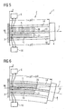
- FIGS. 5 and 6 An even more efficient oscillation of the inertial mass 4 is achieved with the inertial force generator 1, which in FIGS. 5 and 6 is shown.
- This second embodiment is largely identical to the second embodiment.
- One difference is that already in the rest position of the bending arm 2, both transducers 5, 15 are controlled so that they are deflected by a change in length .DELTA.l2, ie, a bias voltage is applied to the transducers 5, 15.
- the first actuator 5 is extended by an additional change in length .DELTA.l2, while the second actuator 15 is shortened by this change in length .DELTA.l2, see Fig.
- the first actuator thus performs a change in length by ⁇ l2 + ⁇ l2, while the second actuator no longer has a change in length.
- the fact is taken into account that a piezoceramic material, starting from its base length, in which no electric field is applied, can only be extended.
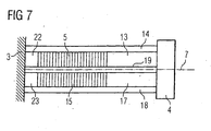
- the bending arm 2 is formed in fiber composite construction.
- the neutral layer 19 and the outer layers 14, 18 are made of fiber composite material, in particular of glass fiber reinforced plastic (GRP).
- GRP glass fiber reinforced plastic
- the arranged on both sides of the transducers 5, 15 spacers 13, 22 and 17, 23 may consist of fiber composites, other lightweight materials (eg, foam material) or metal.
- the transducers 5, 15 are firstly attached to the neutral position 19 on both sides, if necessary by fixing by gluing. Subsequently, the areas are laterally of the transducers 5, 15 filled with corresponding spacers 13, 22 and 18, 23, which may also consist of several fiber composite layers.
- the outer layers 14, 18 are arranged and finally the layered fiber composite material arrangement is injected in a known manner with a resin system and optionally cured under heat, typically by means of known Resin injection method, such as the RTM method.
- the sensitive piezoceramic materials of the actuators 5, 15 are protected from moisture and the ingress of foreign bodies.
- the natural frequency of the bending arm 2 can be set with converter 5, 15 and inertial mass 4 to a desired value.
- a particularly lightweight arrangement in which the mass of the bending arm 2 with converter 5, 15 is much smaller than the inertial mass 4, are created.
- the power generator described above may also be used in a symmetrical arrangement to provide a vibration control device.
- Fig. 8 a first embodiment with two power generators is shown schematically, wherein the bending arms of the two power generators are arranged in extension to each other.
- the bending arms 2 ', 2 "of the respective force generators 1 are arranged on the structure to be vibrationally influenced such that the inertial masses 4', 4" at the same distance from the attachment point 10 'and 10 "are removed
- the in Fig. 8 shown arrangement can by appropriate on the bending arms 2 ', 2 "arranged transducer, which in Fig. 8 are not shown, but have been described in detail in connection with the preceding figures, are controlled such that the inertial masses 4 ', 4 "either parallel, ie in the same direction (eg in the positive y direction), or anti-parallel, ie In a parallel deflection of the inertial masses 4 ', 4 ", forces and moments can be introduced into the structure 3. In an anti-parallel deflection, the force is introduced into the structure 3 torque-free.
- Fig. 9 a further symmetrical arrangement of force generators according to the invention is shown, which shows a so-called “Durchschwinger" -An eleven. Looking at the left area of the Fig. 9 , so this poses as related to the FIGS. 3 to 7 described force generator, but the bending arm 2 'almost over the inertial mass 4, ie in Fig. 9 to the right, the extended end being attached to another structure 3 "or to another location 3" of the structure.
- the arrangement according to Fig. 9 essentially comprises a bending arm whose outer ends, ie the left and the right end in Fig.
- the inertial mass 4 is arranged in the middle of the bending arm and, analogously to the above description, is deflected in a direction perpendicular to the plane of the bending arm, ie in the positive and negative y direction.
- the introduction of vibration forces at the points 3 'and 3 "takes place without torque.
Landscapes
- Engineering & Computer Science (AREA)
- General Engineering & Computer Science (AREA)
- Mechanical Engineering (AREA)
- Physics & Mathematics (AREA)
- Acoustics & Sound (AREA)
- Aviation & Aerospace Engineering (AREA)
- Electromagnetism (AREA)
- Apparatuses For Generation Of Mechanical Vibrations (AREA)
- General Electrical Machinery Utilizing Piezoelectricity, Electrostriction Or Magnetostriction (AREA)
Claims (23)
- Générateur de force (1), qui est conçu pour être monté sur une structure (3) afin d'induire dans celle-ci des forces oscillantes commandables en vue d'agir sur les vibrations de la structure (3), comprenant un bras flexible (2), qui peut être fixé à au moins une extrémité (10) à la structure (3), et une masse d'inertie (4), qui est accouplée au bras flexible (2) à distance de l'extrémité de fixation (10) du bras flexible (2), le bras flexible (2) étant muni d'au moins un convertisseur électromécanique (5, 15), et une commande (6, 16) étant prévue pour le convertisseur (5, 15), pour plier le bras flexible (2) avec la masse d'inertie (4) et le convertisseur (5, 15) et ainsi dévier la masse d'inertie (4), en commandant le convertisseur de telle sorte que des forces oscillantes à amplitude, phase et fréquences variables puissent être induites dans la structure (3), caractérisé en ce qu'une couche extérieure (14, 18) est disposée, de façon à être écartée latéralement de la couche neutre (19) du bras flexible (2), qui passe le long de la ligne médiane (7,12) du bras flexible (2) et au moins un élément d'écartement (13, 17; 13, 17, 22, 23) est disposé entre l'extrémité du convertisseur (5, 15) et la masse d'inertie (4), la couche extérieure étant reliée au convertisseur (5, 15) et/ou à l'élément d'écartement (13, 17; 13, 17, 22, 23) par une liaison par complémentarité de formes et/ou par action de force.
- Générateur de force (1) selon la revendication 1, caractérisé en ce que le convertisseur (5, 15) peut être commandé de telle sorte que des forces oscillantes puissent être induites à au moins deux fréquences dans la structure (3).
- Générateur de force (1) selon la revendication 1 ou 2, caractérisé en ce que le convertisseur (5, 15) peut être commandé de telle sorte que le bras flexible (2) est mobile avec la masse d'inertie (4) et le convertisseur (5, 15) pour former une oscillation dans sa fréquence propre.
- Générateur de force (1) selon l'une quelconque des revendications 1 à 3, caractérisé en ce que la masse d'inertie (4) est un multiple de la masse du bras flexible (2) et du convertisseur (5, 15).
- Générateur de force (1) selon l'une quelconque des revendications 1 à 4, caractérisé en ce que le convertisseur (5, 15) est un actionneur piézoélectrique (5, 15), notamment un élément piézoélectrique à structure empilée, à effet longitudinal (correspondant au coefficient d33).
- Générateur de force (1) selon l'une quelconque des revendications 1 à 5, caractérisé en ce que le convertisseur (5, 15) peut être commandé de telle sorte qu'il exécute une variation en longueur dans le sens longitudinal du bras flexible (2).
- Générateur de force (1) selon l'une quelconque des revendications 1 à 6, caractérisé en ce que le convertisseur (5, 15) est disposé de façon à être parallèle à la couche neutre (19).
- Générateur de force (1) selon la revendication 7, caractérisé en ce qu'à chaque fois au moins un convertisseur (5,15) est disposé sur des côtés réciproquement opposés de la couche neutre (19).
- Générateur de force (1) selon l'une quelconque des revendications 7 ou 8, caractérisé en ce que le convertisseur (5, 15) est relié à la couche neutre (19) par une liaison par complémentarité de formes et/ou par action de force.
- Générateur de force (1) selon l'une quelconque des revendications 1 à 9, caractérisé en ce que le au moins un convertisseur (5, 15) est disposé à l'intérieur du bras flexible (2).
- Générateur de force (1) selon l'une quelconque des revendications 1 à 10, caractérisé en ce que le bras flexible (2) est construit dans un mode de construction renforcé par des fibres, le convertisseur (5, 15) étant intégré à l'intérieur.
- Générateur de force (1) selon l'une quelconque des revendications 1 à 11, caractérisé en ce que le convertisseur (5, 15) est soumis à une précontrainte de pression.
- Générateur de force (1) selon la revendication 12, caractérisé en ce que la précontrainte de pression est empreinte mécaniquement.
- Générateur de force (1) selon l'une quelconque des revendications 1 à 13, caractérisé en ce que le convertisseur (5,15) est soumis lors de sa fabrication à un traitement thermique pour générer la précontrainte de pression.
- Générateur de force (1) selon l'une quelconque des revendications 1 à 14, caractérisé en ce qu'une tension électrique de décalage est appliquée au convertisseur (5, 15).
- Procédé pour faire fonctionner un générateur de force (1) selon l'une quelconque des revendications 1 à 15, caractérisé en ce que, par une commande appropriée du convertisseur électromagnétique (5, 15), le bras flexible (2) est plié avec la masse d'inertie (4) et le convertisseur (5, 15) et ainsi la masse d'inertie (4) est déviée de telle sorte que des forces oscillantes à amplitude, phase et fréquences variables sont générées.
- Procédé selon la revendication 16, caractérisé en ce que le convertisseur (5, 15) est commandé à plusieurs fréquences ou à une plage de fréquences prescrite, afin d'induire des forces oscillantes à au moins deux fréquences dans la structure (3).
- Dispositif agissant sur les vibrations, qui est conçu pour être monté sur au moins une structure (3) afin d'induire dans la structure (3) des forces oscillantes commandables, comprenant deux générateurs de force (1) selon l'une quelconque des revendications 1 à 15, qui sont disposés de telle sorte que le bras flexible (2') du premier générateur de force (1) est disposé dans le prolongement du bras flexible (2") du second générateur de force (1).
- Dispositif selon la revendication 18, caractérisé en ce que les deux générateurs de force (1) sont disposés symétriquement l'un par rapport à l'autre.
- Dispositif selon la revendication 18 ou 19, caractérisé en ce que le premier bras flexible (2') et le second bras flexible (2") sont construits d'une seule pièce.
- Dispositif selon l'une quelconque des revendications 18 à 20, caractérisé en ce que l'extrémité (10') opposée à la masse d'inertie (4') du premier bras flexible (2') et l'extrémité opposée (10") à la masse d'inertie (4") du second bras flexible (2") sont fixées à la structure (3).
- Dispositif selon la revendication 20, caractérisé en ce que le bras flexible construit d'une seule pièce est accouplé à ses extrémités extérieures respectivement à une masse d'inertie (4', 4"), et peut être fixé à la structure (3) dans une zone comprise entre les deux masses d'inertie (4', 4").
- Dispositif selon la revendication 20, caractérisé en ce que le bras flexible construit d'une seule pièce est fixé à ses extrémités extérieures respectivement à au moins une structure (3', 3"), et comprend dans une zone située entre les deux endroits de fixation au moins une masse d'inertie (4).
Applications Claiming Priority (2)
| Application Number | Priority Date | Filing Date | Title |
|---|---|---|---|
| DE102005060779A DE102005060779B4 (de) | 2005-12-16 | 2005-12-16 | Kraftgenerator |
| PCT/EP2006/011569 WO2007073820A1 (fr) | 2005-12-16 | 2006-12-01 | Générateur de force |
Publications (2)
| Publication Number | Publication Date |
|---|---|
| EP1963704A1 EP1963704A1 (fr) | 2008-09-03 |
| EP1963704B1 true EP1963704B1 (fr) | 2010-08-04 |
Family
ID=37888043
Family Applications (1)
| Application Number | Title | Priority Date | Filing Date |
|---|---|---|---|
| EP06818959A Ceased EP1963704B1 (fr) | 2005-12-16 | 2006-12-01 | Générateur de force |
Country Status (6)
| Country | Link |
|---|---|
| US (1) | US20080315725A1 (fr) |
| EP (1) | EP1963704B1 (fr) |
| KR (1) | KR101215673B1 (fr) |
| CN (1) | CN101331339B (fr) |
| DE (2) | DE102005060779B4 (fr) |
| WO (1) | WO2007073820A1 (fr) |
Cited By (2)
| Publication number | Priority date | Publication date | Assignee | Title |
|---|---|---|---|---|
| EP3020638A1 (fr) | 2014-11-11 | 2016-05-18 | Airbus Defence and Space GmbH | Dispositif et procédé de dégivrage et/ou de prévention contre la formation de glace ainsi que corps profilé et aéronef dotés d'un tel dispositif |
| US10442540B2 (en) | 2013-11-13 | 2019-10-15 | Airbus Defence and Space GmbH | Device and method for deicing and/or preventing ice formation and profile element and aircraft having such a device |
Families Citing this family (14)
| Publication number | Priority date | Publication date | Assignee | Title |
|---|---|---|---|---|
| DE102006056757A1 (de) * | 2006-12-01 | 2008-06-05 | Wölfel Beratende Ingenieure GmbH & Co. KG | Aktiver Tilger |
| DE102007039548B3 (de) * | 2007-08-21 | 2009-01-29 | Eads Deutschland Gmbh | System und Verfahren zur Schwingungsbeeinflussung |
| JP5299284B2 (ja) * | 2007-11-21 | 2013-09-25 | コニカミノルタ株式会社 | 圧電アクチュエータ、駆動装置、位置決め装置およびレーザモジュール |
| KR101638175B1 (ko) * | 2008-11-04 | 2016-07-08 | 로오드 코포레이션 | 안정한 고유 주파수를 갖는 공명 관성력 생성기 |
| JP4823368B2 (ja) * | 2010-02-26 | 2011-11-24 | 三菱重工業株式会社 | 振動低減装置および振動低減方法 |
| DE102010021867A1 (de) * | 2010-05-28 | 2011-12-01 | Eurocopter Deutschland Gmbh | Kraftgenerator zur Anbringung an einer Struktur |
| FR2977983B1 (fr) * | 2011-07-11 | 2013-08-16 | Commissariat Energie Atomique | Systeme de conversion d'energie thermique en energie electrique |
| ES2540935T3 (es) * | 2012-07-20 | 2015-07-14 | Airbus Operations S.L. | Medición de las propiedades inerciales de una superficie de control movible |
| EP2743179B1 (fr) | 2012-12-17 | 2016-06-01 | Airbus Defence and Space GmbH | Agencement d'actionneur et agencement de surface de commande, notamment pour un aéronef |
| DE102014110753A1 (de) | 2014-07-29 | 2016-02-04 | Airbus Defence and Space GmbH | Kraftgenerator mit durch elektronisches Bauelement gebildeter Inertialmasse sowie Ansteuerschaltung hierfür |
| US11408480B2 (en) | 2018-12-07 | 2022-08-09 | Itt Manufacturing Enterprises Llc | Adaptive tuned vibration absorber |
| CN113565912B (zh) * | 2021-06-22 | 2023-07-11 | 东风汽车集团股份有限公司 | 一种共振频率自适应快速可调的动力吸振结构及方法 |
| CN114553051A (zh) * | 2022-03-02 | 2022-05-27 | 哈尔滨工业大学 | 一种基于惯性原理的杠杆型能量俘获装置 |
| CN119853498B (zh) * | 2025-03-04 | 2025-11-21 | 东南大学 | 具有偏心质量块的压电梁式双向微机械振动能量收集器 |
Family Cites Families (22)
| Publication number | Priority date | Publication date | Assignee | Title |
|---|---|---|---|---|
| DE2036979A1 (de) * | 1970-07-25 | 1972-02-03 | Hamburger Flugzeugbau Gmbh | Schwingungstilger zum Verringern von Korperschall |
| US4080636A (en) * | 1976-03-19 | 1978-03-21 | Ampex Corporation | System for damping vibrations in a deflectable transducer |
| US4565940A (en) * | 1984-08-14 | 1986-01-21 | Massachusetts Institute Of Technology | Method and apparatus using a piezoelectric film for active control of vibrations |
| JP2559589B2 (ja) * | 1987-05-26 | 1996-12-04 | 株式会社ブリヂストン | 吸振装置 |
| EP0262637B1 (fr) * | 1986-09-29 | 1995-03-22 | Mitsubishi Chemical Corporation | Dispositif d'actionnement piézoélectrique |
| SU1467286A1 (ru) * | 1987-02-23 | 1989-03-23 | Московский Институт Электронного Машиностроения | Гаситель колебаний |
| JPH0763678B2 (ja) | 1988-04-07 | 1995-07-12 | 株式会社村田製作所 | 振動アラーム装置 |
| JPH0659459B2 (ja) * | 1988-11-08 | 1994-08-10 | 株式会社村田製作所 | 振動アラーム装置 |
| JPH0626455A (ja) * | 1992-04-03 | 1994-02-01 | General Electric Co <Ge> | 圧縮機用の動的釣合装置、及び圧縮機により生ずる振動を減衰させる方法 |
| US5245245A (en) * | 1992-05-04 | 1993-09-14 | Motorola, Inc. | Mass-loaded cantilever vibrator |
| JPH07168631A (ja) | 1993-12-13 | 1995-07-04 | Kobe Steel Ltd | 振動制振装置 |
| JP2934723B2 (ja) | 1997-05-19 | 1999-08-16 | 株式会社セラテック | 加振体及びこれを用いた着信装置 |
| DE19739877C2 (de) | 1997-09-11 | 2003-04-17 | Eurocopter Deutschland | Mechanischer Resonator mit variabler Resonanzfrequenz |
| US5945772A (en) * | 1998-05-29 | 1999-08-31 | Motorla, Inc. | Damped resonant piezoelectric alerting device |
| DE10139686B4 (de) * | 2000-10-05 | 2007-02-01 | Eads Deutschland Gmbh | Piezoelektrischer Dehnungsaktuator |
| SE517878C2 (sv) * | 2000-12-08 | 2002-07-30 | Sandvik Ab | Förfarande och anordning för vibrationsdämpning av metalliska verktyg för spånavskiljande bearbetning samt verktyg innefattande en dylik anordning |
| JP3919560B2 (ja) * | 2002-02-26 | 2007-05-30 | キヤノン株式会社 | 振動制御装置及び振動制御方法及び露光装置及びデバイスの製造方法 |
| US7369115B2 (en) * | 2002-04-25 | 2008-05-06 | Immersion Corporation | Haptic devices having multiple operational modes including at least one resonant mode |
| JP4002813B2 (ja) * | 2002-10-15 | 2007-11-07 | 忠司 中沼 | 振動発生装置 |
| DE10351243B4 (de) * | 2003-10-27 | 2005-08-18 | Deutsches Zentrum für Luft- und Raumfahrt e.V. | Adaptiver Schwingungstilger |
| DE102004001470B4 (de) * | 2004-01-08 | 2005-11-03 | Eurocopter Deutschland Gmbh | Mechanischer Resonator |
| US7459835B1 (en) * | 2006-03-06 | 2008-12-02 | Magnecomp Corporation | Loading-protected bending microactuator in additive suspensions |
-
2005
- 2005-12-16 DE DE102005060779A patent/DE102005060779B4/de not_active Expired - Fee Related
-
2006
- 2006-12-01 CN CN2006800473916A patent/CN101331339B/zh not_active Expired - Fee Related
- 2006-12-01 EP EP06818959A patent/EP1963704B1/fr not_active Ceased
- 2006-12-01 US US12/097,726 patent/US20080315725A1/en not_active Abandoned
- 2006-12-01 WO PCT/EP2006/011569 patent/WO2007073820A1/fr not_active Ceased
- 2006-12-01 DE DE502006007613T patent/DE502006007613D1/de active Active
-
2008
- 2008-06-05 KR KR1020087013558A patent/KR101215673B1/ko not_active Expired - Fee Related
Cited By (2)
| Publication number | Priority date | Publication date | Assignee | Title |
|---|---|---|---|---|
| US10442540B2 (en) | 2013-11-13 | 2019-10-15 | Airbus Defence and Space GmbH | Device and method for deicing and/or preventing ice formation and profile element and aircraft having such a device |
| EP3020638A1 (fr) | 2014-11-11 | 2016-05-18 | Airbus Defence and Space GmbH | Dispositif et procédé de dégivrage et/ou de prévention contre la formation de glace ainsi que corps profilé et aéronef dotés d'un tel dispositif |
Also Published As
| Publication number | Publication date |
|---|---|
| DE502006007613D1 (de) | 2010-09-16 |
| WO2007073820A1 (fr) | 2007-07-05 |
| KR101215673B1 (ko) | 2012-12-26 |
| DE102005060779A1 (de) | 2007-06-21 |
| CN101331339A (zh) | 2008-12-24 |
| US20080315725A1 (en) | 2008-12-25 |
| DE102005060779B4 (de) | 2008-07-10 |
| WO2007073820B1 (fr) | 2007-08-30 |
| CN101331339B (zh) | 2011-03-09 |
| KR20080080298A (ko) | 2008-09-03 |
| EP1963704A1 (fr) | 2008-09-03 |
Similar Documents
| Publication | Publication Date | Title |
|---|---|---|
| EP1963704B1 (fr) | Générateur de force | |
| EP0907036B1 (fr) | Résonateur méchanique avec fréquence de résonance variable | |
| EP2673531B1 (fr) | Montage sans vibrations d'un objet sur une structure | |
| EP2140168B1 (fr) | Dispositif d'amortissement de vibrations | |
| DE3821368C2 (fr) | ||
| DE102010039069B4 (de) | Beschleunigungssensor mit einer Dämpfungseinrichtung | |
| DE102007039548B3 (de) | System und Verfahren zur Schwingungsbeeinflussung | |
| EP2577090B1 (fr) | Générateur de force à monter sur une structure | |
| DE102012004808A1 (de) | Vorrichtung zur Beeinflussung der Schwingungsübertragung zwischen zwei Einheiten | |
| EP1927782A1 (fr) | Amortisseur à masse syntonisée actif | |
| DE60028654T2 (de) | Resonante Vorrichtung wie Schläger oder Klopfer | |
| DE102007021337A1 (de) | Piezoelektrische Antriebsvorrichtung | |
| DE60210715T2 (de) | Piezoelektrische Elemente benutzendes Schwingungsregelungssystem | |
| EP1239183A2 (fr) | Procédure et dispositif pour influencer la transmission de vibrations d'un élément vibratoire à une unité liée avec, en particulier les vibrations d'un moteur à la carosserie d'un véhicule | |
| DE102010055848A1 (de) | Ultraschallaktor | |
| EP1996905B1 (fr) | Dispositif de détermination et/ou de surveillance d'un paramètre de traitement | |
| EP2467924B1 (fr) | Résonateur pouvant être syntonisé en fréquence et procédé pour le faire fonctionner | |
| DE10052248C1 (de) | System, enthaltend ein Lager und einen Sensor zur Messung von auf das Lager wirkenden Kräfte | |
| DE102014220293B4 (de) | Schwingungsvorrichtung und Verfahren zur Abstimmung derselben | |
| EP4015271A1 (fr) | Palier élastique | |
| EP4012217B1 (fr) | Dispositif d'absorption par résonance | |
| EP1500183A2 (fr) | Piezomoteur | |
| DE19547184A1 (de) | Kraftsensor | |
| EP4300267A1 (fr) | Dispositif d'entrée avec des éléments de ressort améliorés pour le montage mobile de la partie de commande, élément de ressort correspondant ainsi que procédé de montage | |
| EP1566481A1 (fr) | Mortissement de vibrations d'un racloir |
Legal Events
| Date | Code | Title | Description |
|---|---|---|---|
| PUAI | Public reference made under article 153(3) epc to a published international application that has entered the european phase |
Free format text: ORIGINAL CODE: 0009012 |
|
| 17P | Request for examination filed |
Effective date: 20080715 |
|
| AK | Designated contracting states |
Kind code of ref document: A1 Designated state(s): DE GB IT |
|
| DAX | Request for extension of the european patent (deleted) | ||
| RBV | Designated contracting states (corrected) |
Designated state(s): DE GB IT |
|
| 17Q | First examination report despatched |
Effective date: 20091222 |
|
| GRAP | Despatch of communication of intention to grant a patent |
Free format text: ORIGINAL CODE: EPIDOSNIGR1 |
|
| GRAS | Grant fee paid |
Free format text: ORIGINAL CODE: EPIDOSNIGR3 |
|
| GRAA | (expected) grant |
Free format text: ORIGINAL CODE: 0009210 |
|
| AK | Designated contracting states |
Kind code of ref document: B1 Designated state(s): DE GB IT |
|
| REG | Reference to a national code |
Ref country code: GB Ref legal event code: FG4D Free format text: NOT ENGLISH |
|
| REF | Corresponds to: |
Ref document number: 502006007613 Country of ref document: DE Date of ref document: 20100916 Kind code of ref document: P |
|
| PLBE | No opposition filed within time limit |
Free format text: ORIGINAL CODE: 0009261 |
|
| STAA | Information on the status of an ep patent application or granted ep patent |
Free format text: STATUS: NO OPPOSITION FILED WITHIN TIME LIMIT |
|
| 26N | No opposition filed |
Effective date: 20110506 |
|
| REG | Reference to a national code |
Ref country code: DE Ref legal event code: R097 Ref document number: 502006007613 Country of ref document: DE Effective date: 20110506 |
|
| REG | Reference to a national code |
Ref country code: DE Ref legal event code: R082 Ref document number: 502006007613 Country of ref document: DE Representative=s name: GPI & ASSOCIES, FR |
|
| REG | Reference to a national code |
Ref country code: DE Ref legal event code: R082 Ref document number: 502006007613 Country of ref document: DE Representative=s name: GPI & ASSOCIES, FR |
|
| REG | Reference to a national code |
Ref country code: DE Ref legal event code: R082 Ref document number: 502006007613 Country of ref document: DE Representative=s name: GPI & ASSOCIES, FR Effective date: 20150112 Ref country code: DE Ref legal event code: R081 Ref document number: 502006007613 Country of ref document: DE Owner name: AIRBUS HELICOPTERS DEUTSCHLAND GMBH, DE Free format text: FORMER OWNER: EUROCOPTER DEUTSCHLAND GMBH, 86609 DONAUWOERTH, DE Effective date: 20150112 Ref country code: DE Ref legal event code: R082 Ref document number: 502006007613 Country of ref document: DE Representative=s name: GPI & ASSOCIES, FR Effective date: 20130208 |
|
| PGFP | Annual fee paid to national office [announced via postgrant information from national office to epo] |
Ref country code: DE Payment date: 20171211 Year of fee payment: 12 |
|
| PGFP | Annual fee paid to national office [announced via postgrant information from national office to epo] |
Ref country code: GB Payment date: 20171221 Year of fee payment: 12 |
|
| REG | Reference to a national code |
Ref country code: DE Ref legal event code: R119 Ref document number: 502006007613 Country of ref document: DE |
|
| GBPC | Gb: european patent ceased through non-payment of renewal fee |
Effective date: 20181201 |
|
| PG25 | Lapsed in a contracting state [announced via postgrant information from national office to epo] |
Ref country code: DE Free format text: LAPSE BECAUSE OF NON-PAYMENT OF DUE FEES Effective date: 20190702 |
|
| PG25 | Lapsed in a contracting state [announced via postgrant information from national office to epo] |
Ref country code: GB Free format text: LAPSE BECAUSE OF NON-PAYMENT OF DUE FEES Effective date: 20181201 |
|
| PGFP | Annual fee paid to national office [announced via postgrant information from national office to epo] |
Ref country code: IT Payment date: 20221228 Year of fee payment: 17 |
|
| P01 | Opt-out of the competence of the unified patent court (upc) registered |
Effective date: 20230530 |
|
| PG25 | Lapsed in a contracting state [announced via postgrant information from national office to epo] |
Ref country code: IT Free format text: LAPSE BECAUSE OF NON-PAYMENT OF DUE FEES Effective date: 20231201 |