EP1963733B1 - Systeme d'eclairage comprenant des modules d'eclairage interconnectables - Google Patents
Systeme d'eclairage comprenant des modules d'eclairage interconnectables Download PDFInfo
- Publication number
- EP1963733B1 EP1963733B1 EP06832090A EP06832090A EP1963733B1 EP 1963733 B1 EP1963733 B1 EP 1963733B1 EP 06832090 A EP06832090 A EP 06832090A EP 06832090 A EP06832090 A EP 06832090A EP 1963733 B1 EP1963733 B1 EP 1963733B1
- Authority
- EP
- European Patent Office
- Prior art keywords
- bridge
- connection
- members
- lighting
- terminals
- Prior art date
- Legal status (The legal status is an assumption and is not a legal conclusion. Google has not performed a legal analysis and makes no representation as to the accuracy of the status listed.)
- Active
Links
Images




Classifications
-
- F—MECHANICAL ENGINEERING; LIGHTING; HEATING; WEAPONS; BLASTING
- F21—LIGHTING
- F21V—FUNCTIONAL FEATURES OR DETAILS OF LIGHTING DEVICES OR SYSTEMS THEREOF; STRUCTURAL COMBINATIONS OF LIGHTING DEVICES WITH OTHER ARTICLES, NOT OTHERWISE PROVIDED FOR
- F21V23/00—Arrangement of electric circuit elements in or on lighting devices
- F21V23/06—Arrangement of electric circuit elements in or on lighting devices the elements being coupling devices, e.g. connectors
-
- F—MECHANICAL ENGINEERING; LIGHTING; HEATING; WEAPONS; BLASTING
- F21—LIGHTING
- F21S—NON-PORTABLE LIGHTING DEVICES; SYSTEMS THEREOF; VEHICLE LIGHTING DEVICES SPECIALLY ADAPTED FOR VEHICLE EXTERIORS
- F21S2/00—Systems of lighting devices, not provided for in main groups F21S4/00 - F21S10/00 or F21S19/00, e.g. of modular construction
- F21S2/005—Systems of lighting devices, not provided for in main groups F21S4/00 - F21S10/00 or F21S19/00, e.g. of modular construction of modular construction
-
- F—MECHANICAL ENGINEERING; LIGHTING; HEATING; WEAPONS; BLASTING
- F21—LIGHTING
- F21V—FUNCTIONAL FEATURES OR DETAILS OF LIGHTING DEVICES OR SYSTEMS THEREOF; STRUCTURAL COMBINATIONS OF LIGHTING DEVICES WITH OTHER ARTICLES, NOT OTHERWISE PROVIDED FOR
- F21V21/00—Supporting, suspending, or attaching arrangements for lighting devices; Hand grips
- F21V21/005—Supporting, suspending, or attaching arrangements for lighting devices; Hand grips for several lighting devices in an end-to-end arrangement, i.e. light tracks
-
- F—MECHANICAL ENGINEERING; LIGHTING; HEATING; WEAPONS; BLASTING
- F21—LIGHTING
- F21Y—INDEXING SCHEME ASSOCIATED WITH SUBCLASSES F21K, F21L, F21S and F21V, RELATING TO THE FORM OR THE KIND OF THE LIGHT SOURCES OR OF THE COLOUR OF THE LIGHT EMITTED
- F21Y2115/00—Light-generating elements of semiconductor light sources
- F21Y2115/10—Light-emitting diodes [LED]
Definitions
- the present invention relates to a lighting system comprising a plurality of interconnectable polygonal lighting modules.
- Lighting systems of the kind referred to here generally consist of polygonal lighting modules, i.e. light emitting modules, which are arranged to form an arrangement of a desired shape and size. For example, walls are fully or partly covered with a lighting module arrangement for displaying large images, or three-dimensional structures are formed for aesthetic applications.
- polygonal lighting modules i.e. light emitting modules
- walls are fully or partly covered with a lighting module arrangement for displaying large images, or three-dimensional structures are formed for aesthetic applications.
- One lighting system is disclosed in published US patent application No. 2005/0116667 A1 .
- the lighting modules are thin building blocks called tiles, and the lighting modules are provided with electrical and mechanical connection means for interconnecting the lighting modules. These connection means are provided at the sides of the lighting modules.
- US 2005/0116667 does not disclose any solution of how to actually design the lighting modules in order to obtain the interconnections.
- the electrical connections are used for powering electronic circuitry of the lighting modules. It is desirable that the lighting modules can be freely assembled to a large unit, or arrangement, without having to consider orientation of each lighting module. In other words, it is desirable that arbitrary sides of different lighting modules can face each other.
- a tube light system is disclosed. Two tube lights can be connected in line or at right angles. Therefore, the tube lights are provided with four holes on each side, and a connector is provided with two pairs of parallel contact pins for connecting two adjacent tube lights.
- a lighting system comprising a plurality of interconnectable polygonal lighting modules, wherein each lighting module has a plurality of connection members, each comprising at least one electrical terminal, which are arranged rotationally symmetrically at the lighting module.
- the lighting system further comprises bridge members, wherein each bridge member comprises bridge terminals and is mountable at neighboring connection members, each associated with a respective lighting module, to form a bridge providing an electric connection between connection terminals of the connection members.
- connection member structure that is rotationally symmetrical, and by using separate bridge members a degree of interconnectability freedom is introduced, which is useful for enabling a simple connection of lighting modules at an arbitrary rotation.
- both DC power and AC power can be used for energizing the lighting modules.
- connection members arranged at the corners, i.e. at four corners of a square module or at six corners of a hexagonal module, of the polygonal lighting module can be the only connection members, or they can be combined with side connection members as well, or only side connection members can be used, as defined in claim 4.
- a side bridge member contains at least two terminals.
- the minimum of two terminals is useful for a combination of corner and side connection members, where, for each side of the lighting module, one power connection, such as a neutral connection for AC or a minus connection for DC, is connected to the corner terminals and the other, i.e. the line connection or the plus connection, is connected to the side terminal. Further options will be explained below.
- connection members are provided. Then, preferably, there are at least four bridge terminals for connecting at least two connection terminals of each connection member with corresponding terminals of the neighboring connection member.
- connection terminals facing each other and belonging to different are always associated with different polarities.
- bridge member In conjunction with the just mentioned bridge member a totally failsafe mounting is achieved.
- a mechanical connection is obtained by means of the bridge member.
- a lighting module arrangement can be assembled without any further mechanical connectors.
- a combined mechanical and electrical connection is obtained. The same applies to the embodiment defined in claim 14.
- a plurality of lighting modules are assembled to an arrangement of desired size and shape.
- the lighting modules are designed to be interconnectable.
- a straightforward solution to the problem of electrically interconnecting lighting modules 101 is shown in Fig. 1 .
- At each side of the lighting module there are provided one positive terminal 103 and one negative terminal 105. All positive terminals are interconnected inside the lighting module 101, and so are all the negative terminals 105. Terminals of the same polarity, such as positive terminals 103 or negative terminals 105, located on neighboring lighting modules 101 are positioned side by side when the lighting modules 101 are assembled to a lighting module arrangement of desired shape and size.
- each lighting module 201 is provided with a DC connection member 203 at each side thereof. Internally of the lighting module 201 the DC connection members 203 are connected in parallel to internal circuitry. Each DC connection member 203 comprises connection terminals including a positive terminal 205 and a negative terminal 207. All positive terminals 205 of the lighting module 201 are connected with each other, and so are all negative terminals 207 as well.
- connection members 203 of each lighting module 201 are equally directed, and the connection terminals 205, 207 are alternately arranged, as regards the terminal polarities, along a circumference of the lighting module 201, for example clockwise as indicated by the circular arrow.
- the connection members 203 are symmetrically arranged at all sides of the lighting module 201. This means that it does not matter how the lighting module 201 is oriented in relation to neighboring lighting modules 201. On the other hand, this also means that terminals of different polarities, located on neighboring lighting modules 201, are positioned side by side in opposite to the above-mentioned straightforward solution. Thus, they must not be directly engaged with each other.
- the lighting system according to this invention further comprises bridge members.
- the wiring of one embodiment of a bridge member 601 is shown in Fig. 6 .
- such bridge members 601 are mounted on every connection member on every lighting module 303 in the arrangement 301.
- Each bridge member 601 is mountable at two neighboring DC connection members, each associated with a respective lighting module 303.
- the bridge member 601 forms a bridge providing an electric connection between terminals of equal polarity of the two DC connection members.
- the bridge member 601 is provided with four-bridge terminals 607a-d, which is arranged in the corners of a rectangle and which is diagonally interconnected by means of crossing wires 603, 605.
- a DC power source module 305 which is provided with a connection member of the same type as those of the lighting modules 303 is connected to one of the lighting modules 303 by means of a bridge member 601.
- the bridge member 401 comprises a body 403, which is of an insulating material and has a U-shaped cross-section, four metal clamps 405 rectangular arranged in pairs close to the respective ends of the body 403, and the wires 603, 605 mentioned above.
- the metal clamps 405 correspond to the above-mentioned bridge terminals 607a-d.
- the body 403 consists of a bottom plate 407 and opposite long side wall plates 409 extending perpendicularly to the bottom plate 407 and being joined with the bottom plate 407 at the long sides thereof.
- the side wall plates 409 are integral with the bottom plate 407.
- Each lighting module 411 is basically brick shaped, as shown in Fig. 15 . It has a front plate 413, which typically are a diffuser, sidewalls 414 and a rear plate 419. The rear plate is provided with four elongated holes 421, one at each side of the lighting module 411, for receiving the bridge members 401.
- Each lighting module 411 has a connection member 415 comprising a wall portion 416 of the sidewall 414 and two longitudinally spaced contact elements 417. The contact elements 417 are fastened on said wall portion 416 on an inwardly, i.e. towards the inner area of the lighting module 411, facing side thereof.
- connection members 415 When assembling two lighting modules 411, they are pushed or shifted together such that their respective connection members 415 abut on each other. Then, the bridge member 401 is forced down onto the connection members 415 until the bottom plate 407 of the bridge member 401 abuts on upper long side edges of the wall portions 416. Then the metal clamps 405 have made contact with the contact elements 417 of the connection members 415. Thereby electrical connection has been established between the lighting modules 411. Additionally the bridge member 401 mechanically clamps the lighting modules 411 together.
- the basic shape and structure of the bridge member 501 and the connection member is the same but the terminals are different.
- the contact elements of the connection member 515 are constituted by pins and the bridge terminals 505 are constituted by sockets.
- a lighting module 701 comprises merely corner connection members 703 and corner bridge members 705, also shown at 1101 in Fig. 11 .
- Each corner connection member 701 consists of a corner connection terminal 703, shown at 1105 in Fig. 11 .
- the corner connection terminals 703, 1105 are alternately interconnected.
- the corner connection terminals 703, 1105 are interconnected in pairs diagonally of the lighting module 701.
- the corner bridge member 1101 has four legs, constituting corner bridge terminals 1103, which are mountable at corner connection terminals 1105. All the corner bridge terminals 1103 are interconnected.
- the corner bridge member 705, 1101 interconnects four corner connection terminals, one on each lighting module of four neighboring modules 701, thereby feeding a power of a certain polarity that has been applied to one corner connection terminal 703, 1105 of a lighting module 701 to the other three corner connection terminals.
- the corner bridge terminals 1103 are positioned at the corners of a square, and they are formed as pins, which fit into the corner connection terminals, which are formed as sockets.
- the corner bridge members 705 provide mechanical connection between the lighting modules 701.
- the corner connection terminals 703 of a first polarity are also connected to a first input terminal of a common rectifier bridge 711, and the terminals of a second polarity are connected to a second input terminal of the rectifier bridge 711.
- the rectifier bridge 711 is a diode rectifier bridge, of a kind called Graetz rectifier.
- the rectifier bridge 711 rectifies input AC power equally, irrespective of which corner connection terminals are connected to which polarity, i.e. line or neutral, of the power source. The same is true for a DC power source, where the polarities are plus and minus.
- the rectifier bridge 711 might be preceded by transformer in order to lower an input AC voltage, if required. On the other hand this alternative is an AC only solution.
- each corner connection member 1303 is formed as twin members.
- each corner connection member 1303 has two connection terminals 1305, 1307, which are arranged close to the corner of the lighting module 1301, but at two different sides thereof.
- the terminals 1305, 1307 are interconnected.
- the corner connection members 1303 are diagonally interconnected in pairs. From one manufacture point of view, the twin members are preferred before the single corner members.
- each connection member 1403 of the lighting module is arranged at a considerably longer distance from the corners of the lighting module 1401. They are even closer to the center of the lighting module 1401 than corners thereof.
- a disadvantage is the size of the bridge members 1405.
- Each bridge member 1405 still interconnects four lighting modules 1401. The closer to the center of the lighting module 1401 the connection members 1403 are located, the closer to the size of the lighting module the size of the bridge member 1405 gets.
- each connection member 1403 of the lighting module is arranged at a bisector of a respective corner of the lighting module. This definition also includes at least all embodiments of the corner connection members.
- Fig. 12 a schematic diagram of the diode bridge 1201 is shown. Seen from the output terminals 1203, 1205 the bridge consists of four diodes arranged in two parallel branches extending between the output terminals 1203, 1205. Each branch has two series connected diodes 1211. Each one of the input terminals 1207, 1209 is connected to a respective branch at a point between the diodes 1211. Considering the fact that a regular diode has a threshold voltage of approximately 0.75V, an input voltage will drop about 1.5V when passing the diode bridge 1201. Consequently, it is an advantage to combine the diode bridge with a DC/DC converter 1213, and use a high voltage AC power source, such as a mains AC voltage.
- a high voltage AC power source such as a mains AC voltage.
- each lighting module 801 has side as well as corner connection members 803, 805, which are connected to a rectifier bridge 807.
- the side connection members are interconnected, and the corner connection members are interconnected.
- the corner connection members 805 all have the same polarity, and the side connection members have the same polarity.
- the corner bridge member 1101 described above is mountable on these corner connection members 805 as well.
- Each side connection member contains a single terminal.
- An appropriate side bridge member being half of a side bridge member shown in Fig. 9 , to be described below, has two terminals, which are mountable on the side connection terminals 803 of the side connection members 803 of two neighboring lighting modules 801. Also in this embodiment both AC and DC power supply can be used.
- a power supply contact 809 is connected to the corner and side connection members 805, 803 of one side of one of the lighting modules 801.
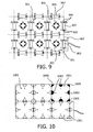
- each side bridge member 903 contains four side bridge terminals 909.
- the bridge terminals 909 are interconnected in pairs transversal of the bridge member rather than diagonally. The pairs are spaced along the side of the lighting module 901.
- two connection terminals arranged on neighboring lighting modules 901, and facing each other are interconnected by means of the bridge member 903.
- a fifth embodiment of the lighting system comprises lighting modules 1001 having a combination of corner and side connection members 1003, 1005, just like the lighting modules of the third embodiment described above.
- the lighting modules do not have rectifier bridges. They are meant for DC supply only.
- All corner connection members have terminals of a first polarity, such as minus, and all side connection members have terminals of a second polarity, such as plus.
- the lighting modules are typically provided with connection members at their sides or their corners or both.
- Bridging members are provided. They are mounted at the connection members for interconnecting terminals thereof.
- the bridging members act as mechanical clamps.
Landscapes
- Engineering & Computer Science (AREA)
- General Engineering & Computer Science (AREA)
- Arrangement Of Elements, Cooling, Sealing, Or The Like Of Lighting Devices (AREA)
- Non-Portable Lighting Devices Or Systems Thereof (AREA)
- Circuit Arrangement For Electric Light Sources In General (AREA)
- Lasers (AREA)
Claims (15)
- Système d'éclairage comprenant une pluralité de modules d'éclairage polygonaux interconnectables (201, 303), où chaque module d'éclairage comporte une pluralité d'organes de connexion (203), comprenant chacun au moins une borne électrique (205, 207), qui sont agencés selon une symétrie de rotation au niveau du module d'éclairage (201, 303), ledit système d'éclairage comprenant en outre des organes de pont (601), où chaque organe de pont (601) comprend des bornes de pont (607 a à d) et peut être monté au niveau d'organes de connexion voisins (203), chacun associé à un module d'éclairage (201, 303) respectif, pour former un pont assurant une connexion électrique entre des bornes de connexion (205, 207) des organes de connexion (203), caractérisé en ce que lesdits organes de connexion (203) se composent d'organes de connexion à courant continu, chacun agencé le long d'un côté respectif du module d'éclairage (201, 303), et chacun comprenant deux bornes de connexion (205, 207) pouvant être connectées à différentes polarités, où chaque organe de pont (601) peut être monté au niveau de deux organes de connexion à courant continu (203) voisins, chacun associé à un module d'éclairage (201, 303) respectif, où chacun desdits organes de pont (601) comprend quatre bornes de pont (607 a à d) agencées aux coins d'un rectangle et diagonalement interconnectées en paires, qui peuvent être connectées à des polarités différentes.
- Système d'éclairage selon la revendication 1, dans lequel lesdits organes de connexion sont connectés à un redresseur en pont.
- Système d'éclairage selon la revendication 2, dans lequel lesdits organes de connexion comprennent des organes de connexion en coin, chacun comprenant une borne de connexion en coin, où chaque coin du module d'éclairage est pourvu d'un tel organe de connexion en coin.
- Système d'éclairage selon la revendication 2 ou 3, dans lequel lesdits organes de connexion comprennent des organes de connexion latéraux, chacun comprenant une borne de connexion latérale, où chaque côté du module d'éclairage est pourvu d'un tel organe de connexion latéral.
- Système d'éclairage selon la revendication 4, dans lequel lesdits organes de pont comprennent des organes de pont latéraux, chacun pourvu de deux bornes de pont latérales interconnectées, qui peuvent être montées au niveau de deux bornes de connexion latérales voisines, qui sont chacune associées à un module d'éclairage respectif.
- Système d'éclairage selon la revendication 3, 4 ou 5, dans lequel lesdits organes de pont comprennent des organes de pont en coin, chacun pourvu de bornes de pont en coin qui peuvent être montées au niveau de bornes de connexion en coin voisines, qui sont chacune associées à un module d'éclairage respectif, où les bornes de pont en coin de chaque organe de pont en coin sont interconnectées.
- Système d'éclairage selon la revendication 2, dans lequel lesdits organes de connexion se composent d'organes de connexion latéraux, chacun agencé au niveau d'un côté respectif du module d'éclairage.
- Système d'éclairage selon la revendication 7, dans lequel lesdits organes de pont se composent d'organes de pont latéraux, comprenant chacun quatre bornes de pont latérales, qui sont interconnectées en paires, où chacune desdites paires de bornes de pont latérales peut être montée au niveau de deux organes de connexion latéraux voisins, chacun associé à un module d'éclairage respectif.
- Système d'éclairage selon l'une quelconque des revendications précédentes, dans lequel lesdits organes de connexion peuvent être alimentés en énergie par l'une quelconque parmi une alimentation alternative et une alimentation continue.
- Système d'éclairage comprenant une pluralité de modules d'éclairage polygonaux interconnectables (801), où chaque module d'éclairage (801) comporte une pluralité d'organes de connexion (203), comprenant chacun au moins une borne électrique (205, 207), qui sont agencés selon une symétrie de rotation au niveau du module d'éclairage (801), ledit système d'éclairage comprenant en outre des organes de pont (1101), où chaque organe de pont (1101) comprend des bornes de pont (1103) et peut être monté au niveau d'organes de connexion (803, 805) voisins, chacun associé à un module d'éclairage (801) respectif, pour former un pont assurant une connexion électrique entre des bornes de connexion des organes de connexion (803, 805), caractérisé en ce que lesdits organes de connexion électrique (803, 805) se composent d'organes de connexion à courant continu, comprenant des organes de connexion en coin (805), qui peuvent être connectés à une première polarité et qui sont chacun agencés au niveau d'un coin respectif du module d'éclairage (801), et comprenant de organes de connexion latéraux (803) qui sont chacun agencés au niveau d'un côté respectif du module d'éclairage et qui peuvent être connectés à une seconde polarité opposée.
- Système d'éclairage selon la revendication 1 ou 10, dans lequel lesdites bornes de connexion sont agencées en alternance par rapport à la polarité le long de la circonférence du module d'éclairage.
- Système d'éclairage selon l'une quelconque des revendications précédentes, dans lequel lesdits organes de pont assurent en outre une connexion mécanique entre les organes de connexion pontés.
- Système d'éclairage selon l'une quelconque des revendications précédentes, dans lequel lesdites bornes de pont comprennent des pinces en métal, qui sont agencées pour venir en butée contre des parties de contact électrique desdites bornes de connexion et serrer les organes de connexion ensemble.
- Système d'éclairage selon l'une quelconque des revendications précédentes, dans lequel chaque borne de pont comprend l'un des éléments parmi une broche et une prise, et chaque borne de connexion comprend un élément parmi une broche et une prise, de telle sorte que les broches et les prises soient disposées pour être enclenchées.
- Système d'éclairage selon l'une quelconque des revendications précédentes, dans lequel lesdits organes de connexion sont agencés à la périphérie du module d'éclairage.
Priority Applications (1)
| Application Number | Priority Date | Filing Date | Title |
|---|---|---|---|
| EP06832090A EP1963733B1 (fr) | 2005-12-16 | 2006-12-05 | Systeme d'eclairage comprenant des modules d'eclairage interconnectables |
Applications Claiming Priority (3)
| Application Number | Priority Date | Filing Date | Title |
|---|---|---|---|
| EP05112322 | 2005-12-16 | ||
| PCT/IB2006/054604 WO2007069130A2 (fr) | 2005-12-16 | 2006-12-05 | Système d'éclairage comprenant des modules d'éclairage interconnectables |
| EP06832090A EP1963733B1 (fr) | 2005-12-16 | 2006-12-05 | Systeme d'eclairage comprenant des modules d'eclairage interconnectables |
Publications (2)
| Publication Number | Publication Date |
|---|---|
| EP1963733A2 EP1963733A2 (fr) | 2008-09-03 |
| EP1963733B1 true EP1963733B1 (fr) | 2011-03-02 |
Family
ID=37950612
Family Applications (1)
| Application Number | Title | Priority Date | Filing Date |
|---|---|---|---|
| EP06832090A Active EP1963733B1 (fr) | 2005-12-16 | 2006-12-05 | Systeme d'eclairage comprenant des modules d'eclairage interconnectables |
Country Status (9)
| Country | Link |
|---|---|
| US (2) | US8111022B2 (fr) |
| EP (1) | EP1963733B1 (fr) |
| JP (1) | JP5033138B2 (fr) |
| KR (1) | KR101249238B1 (fr) |
| CN (1) | CN101331356B (fr) |
| AT (1) | ATE500468T1 (fr) |
| DE (1) | DE602006020486D1 (fr) |
| TW (1) | TW200731873A (fr) |
| WO (1) | WO2007069130A2 (fr) |
Cited By (1)
| Publication number | Priority date | Publication date | Assignee | Title |
|---|---|---|---|---|
| CN102192429A (zh) * | 2011-05-23 | 2011-09-21 | 中山市科顺分析测试技术有限公司 | Led柔性灯带 |
Families Citing this family (52)
| Publication number | Priority date | Publication date | Assignee | Title |
|---|---|---|---|---|
| JP5023403B2 (ja) * | 2007-08-09 | 2012-09-12 | Necライティング株式会社 | 照明装置 |
| DE202007011884U1 (de) * | 2007-08-27 | 2007-10-25 | Osram Gesellschaft mit beschränkter Haftung | Mobile LED-Leuchte |
| DE102007041136A1 (de) | 2007-08-30 | 2009-03-05 | Osram Opto Semiconductors Gmbh | LED-Gehäuse |
| DE102007044566A1 (de) * | 2007-09-07 | 2009-03-12 | Arnold & Richter Cine Technik Gmbh & Co. Betriebs Kg | Beleuchtungssystem |
| US8310175B2 (en) | 2008-05-28 | 2012-11-13 | Lite-On It Corporation | Modular lamp system |
| JP2010177048A (ja) * | 2009-01-29 | 2010-08-12 | Yamagata Promotional Organization For Industrial Technology | 照明装置 |
| DE102009017162B4 (de) * | 2009-04-09 | 2012-08-02 | P.H. Wert-Design E.K. | Modulsystem zur Schaffung einer Leuchte |
| EP2427689A1 (fr) * | 2009-05-08 | 2012-03-14 | Koninklijke Philips Electronics N.V. | Unité d'éclairage |
| EP2256720A1 (fr) * | 2009-05-29 | 2010-12-01 | Koninklijke Philips Electronics N.V. | Système intelligent de carreaux d'éclairage alimentés par plusieurs sources d'alimentation |
| JP5290090B2 (ja) * | 2009-08-26 | 2013-09-18 | パナソニック株式会社 | 発光装置 |
| JP5492511B2 (ja) * | 2009-09-25 | 2014-05-14 | パナソニック株式会社 | 発光装置 |
| CN102667309A (zh) * | 2009-11-13 | 2012-09-12 | 皇家飞利浦电子股份有限公司 | 包含磁性紧固装置的模块化照明单元 |
| CN101769465B (zh) * | 2010-01-28 | 2012-07-04 | 深圳市中电照明股份有限公司 | Led灯具单元体及led组合灯具 |
| WO2011124689A1 (fr) * | 2010-04-09 | 2011-10-13 | Ledon Oled Lighting Gmbh & Co. Kg | Module d'éclairage et lampe |
| US8231258B2 (en) * | 2010-04-10 | 2012-07-31 | Lg Innotek Co., Ltd. | Lighting module and lighting apparatus including the same |
| US8125126B2 (en) * | 2010-05-07 | 2012-02-28 | Industrial Technology Research Institute | Multi-facet light emitting lamp |
| DE102010039956A1 (de) * | 2010-08-30 | 2012-03-01 | Osram Opto Semiconductors Gmbh | Lichtquellenvorrichtung und Lichtquellenanordnung |
| US9046233B2 (en) | 2010-09-27 | 2015-06-02 | Au Optronics Corporation | Assemblage structure for OLED lighting modules |
| DE102010047336B3 (de) * | 2010-10-01 | 2012-02-02 | Petra Heusel | Beleuchtungssystem |
| DE102010038251A1 (de) * | 2010-10-18 | 2012-04-19 | Koninklijke Philips Electronics N.V. | OLED-Leuchtmittel für eine Leuchte |
| DE102010038252A1 (de) | 2010-10-18 | 2012-04-19 | Koninklijke Philips Electronics N.V. | Fassung für eine Leuchte mit OLED-Leuchtmittel |
| JP5943937B2 (ja) * | 2010-12-16 | 2016-07-05 | コーニンクレッカ フィリップス エヌ ヴェKoninklijke Philips N.V. | Ledに基づく組立品 |
| RU2605452C2 (ru) * | 2011-04-18 | 2016-12-20 | Маримилс Ой | Светящаяся полоса и система светящихся полос |
| DE102011077687B4 (de) * | 2011-06-17 | 2021-05-12 | Pictiva Displays International Limited | Organische leuchtdiode, verfahren zur herstellung einer organischen leuchtdiode und modul mit mindestens zwei organischen leuchtdioden |
| JP6058689B2 (ja) * | 2011-12-05 | 2017-01-11 | フィリップス ライティング ホールディング ビー ヴィ | 照明システム |
| KR200483092Y1 (ko) * | 2012-04-10 | 2017-04-05 | 주식회사 케이엠더블유 | 확장이 용이한 엘이디 실내 조명장치 |
| WO2014002085A1 (fr) | 2012-06-26 | 2014-01-03 | M.N. Wasserman Ltd. | Système d'éclairage modulaire |
| DE102012219364A1 (de) * | 2012-10-23 | 2014-04-24 | Allnet Gmbh | Verbindbare LED-Module und Verfahren zum Verbinden von LED-Modulen |
| US9353918B2 (en) * | 2012-12-15 | 2016-05-31 | Lumenetix, Inc. | System and method for communication among linear light modules in a lighting system |
| DE102013201219A1 (de) * | 2013-01-25 | 2014-07-31 | Osram Opto Semiconductors Gmbh | Leuchtmittel |
| JP2014154212A (ja) * | 2013-02-04 | 2014-08-25 | Toshiba Corp | 有機電界発光素子、照明装置及び照明システム |
| DE102013208392A1 (de) * | 2013-05-07 | 2014-11-13 | Osram Gmbh | LED-Modul und Leuchte mit einem LED-Modul |
| CN105379421B (zh) * | 2013-05-13 | 2018-09-21 | 飞利浦照明控股有限公司 | 具有内建可编程性的集成的微发光二极管模块 |
| DE102013112270B4 (de) * | 2013-11-07 | 2024-02-22 | Pictiva Displays International Limited | Bauelementanordnung |
| EP3143323B1 (fr) * | 2014-04-29 | 2019-10-09 | Cooledge Lighting, Inc. | Systèmes modulaires d'éclairage à del |
| FR3023903B1 (fr) * | 2014-07-15 | 2020-04-03 | Ledixis | Ensemble destine a faconner un systeme d'eclairage modulaire a l'aide d'elements de couplage assurant une liaison auto portante |
| FI126862B (fi) * | 2014-08-29 | 2017-06-30 | Absolute Module Oy | Modulaarinen kalustejärjestely ja sen mukainen menetelmä |
| JP6312940B2 (ja) * | 2015-02-05 | 2018-04-18 | フィリップス ライティング ホールディング ビー ヴィ | Ledモジュール |
| US9477438B1 (en) * | 2015-09-25 | 2016-10-25 | Revolution Display, Llc | Devices for creating mosaicked display systems, and display mosaic systems comprising same |
| US10746358B1 (en) | 2016-03-02 | 2020-08-18 | Cooledge Lighting Inc. | Lighting systems incorporating connections for signal and power transmission |
| US11274823B1 (en) | 2016-03-02 | 2022-03-15 | Cooledge Lighting, Inc. | Lighting systems incorporating connections for signal and power transmission |
| US10344954B1 (en) | 2016-03-02 | 2019-07-09 | Cooledge Lighting Inc. | Lighting systems incorporating connections for signal and power transmission |
| JP6360514B2 (ja) * | 2016-03-31 | 2018-07-18 | Hoya Candeo Optronics株式会社 | Led基板及びそれを有する光照射装置 |
| US11107151B2 (en) * | 2017-12-21 | 2021-08-31 | Google Llc | Interactive kiosk having modular and relocatable LED arrays |
| US10980187B2 (en) | 2019-02-21 | 2021-04-20 | Omachron Intellectual Property Inc. | Lighting system for indoor cultivation facility |
| DE102019108726A1 (de) * | 2019-04-03 | 2020-10-08 | Magnwall Gmbh | System für einen Präsentations-, Verkaufs- oder Messestand und/oder für den Ladenbau sowie stromleitendes Wandelement in einem solchen System |
| EP4055316A1 (fr) * | 2019-11-04 | 2022-09-14 | Signify Holding B.V. | Système de raccordement pour luminaire et système d'éclairage utilisant le système de raccordement |
| CN110985904A (zh) * | 2020-01-02 | 2020-04-10 | 东莞市泰亮半导体照明有限公司 | 一种模组式灯具 |
| NL2024980B1 (en) * | 2020-02-24 | 2021-10-14 | Schreder Sa | Modular luminaire assemblies for tunnels |
| CN115498472A (zh) * | 2021-06-18 | 2022-12-20 | 赛万特科技有限责任公司 | 电气连接装置和照明系统 |
| CN115064088B (zh) * | 2022-05-18 | 2025-08-26 | 浙江威谷光电科技有限公司 | 一种基于led显示面板的显示屏 |
| WO2024007302A1 (fr) * | 2022-07-08 | 2024-01-11 | 深圳市豪恩智能物联股份有限公司 | Connecteur et lumières épissées |
Family Cites Families (14)
| Publication number | Priority date | Publication date | Assignee | Title |
|---|---|---|---|---|
| US4413311A (en) * | 1981-09-01 | 1983-11-01 | Philip Orenstein | Connection system for joining illuminated modules |
| US4532579A (en) * | 1984-04-13 | 1985-07-30 | Bill Merryman | Illuminated interconnectable sign module |
| US5628557A (en) * | 1995-06-16 | 1997-05-13 | Shining Blick Enterprises Co., Ltd. | Assembly tube light for window display |
| DE10012734C1 (de) * | 2000-03-16 | 2001-09-27 | Bjb Gmbh & Co Kg | Illuminationsbausatz für Beleuchtungs-, Anzeige- oder Hinweiszwecke sowie Steckverbinder für einen solchen Illuminationsbausatz |
| JP2001352180A (ja) * | 2000-06-09 | 2001-12-21 | Mitsubishi Electric Corp | 電子機器、電子機器の連結器具、及び電子機器の連結構造 |
| US7358929B2 (en) * | 2001-09-17 | 2008-04-15 | Philips Solid-State Lighting Solutions, Inc. | Tile lighting methods and systems |
| CN100559070C (zh) * | 2002-02-21 | 2009-11-11 | 皇家飞利浦电子股份有限公司 | 包含邻近的发光装置的天花板及其安装方法 |
| ITBS20020043U1 (it) * | 2002-04-12 | 2003-10-13 | Flos Spa | Giunto per il collegamento meccanico e elettrico di apparecchi di illuminazione in linea e/o ad angolo |
| US7380961B2 (en) * | 2002-04-24 | 2008-06-03 | Moriyama Sangyo Kabushiki Kaisha | Light source coupler, illuminant device, patterned conductor, and method for manufacturing light source coupler |
| US7080927B2 (en) * | 2003-07-09 | 2006-07-25 | Stephen Feuerborn | Modular lighting with blocks |
| TWI254776B (en) * | 2003-09-24 | 2006-05-11 | Toshiba Lighting & Technology | Illumination device |
| US8522494B2 (en) * | 2004-03-11 | 2013-09-03 | Barco, Inc. | System for creating a tensioned wall composed of individual LED tiles |
| ITMI20040756A1 (it) * | 2004-04-16 | 2004-07-16 | Vlm Spa | Sistema di illuminazione modulare comprendente moduli di illuminazione a led ad alta potenza |
| JP4784403B2 (ja) | 2006-06-08 | 2011-10-05 | パナソニック電工株式会社 | 発光パネルシステム |
-
2006
- 2006-12-05 US US12/097,283 patent/US8111022B2/en active Active
- 2006-12-05 DE DE602006020486T patent/DE602006020486D1/de active Active
- 2006-12-05 AT AT06832090T patent/ATE500468T1/de not_active IP Right Cessation
- 2006-12-05 KR KR1020087017238A patent/KR101249238B1/ko not_active Expired - Fee Related
- 2006-12-05 CN CN2006800470138A patent/CN101331356B/zh active Active
- 2006-12-05 JP JP2008545166A patent/JP5033138B2/ja active Active
- 2006-12-05 WO PCT/IB2006/054604 patent/WO2007069130A2/fr not_active Ceased
- 2006-12-05 EP EP06832090A patent/EP1963733B1/fr active Active
- 2006-12-13 TW TW095146688A patent/TW200731873A/zh unknown
-
2012
- 2012-01-04 US US13/343,104 patent/US8362715B2/en active Active
Cited By (2)
| Publication number | Priority date | Publication date | Assignee | Title |
|---|---|---|---|---|
| CN102192429A (zh) * | 2011-05-23 | 2011-09-21 | 中山市科顺分析测试技术有限公司 | Led柔性灯带 |
| CN102192429B (zh) * | 2011-05-23 | 2013-06-26 | 中山市科顺分析测试技术有限公司 | Led柔性灯带 |
Also Published As
| Publication number | Publication date |
|---|---|
| US8362715B2 (en) | 2013-01-29 |
| KR20080075227A (ko) | 2008-08-14 |
| CN101331356A (zh) | 2008-12-24 |
| US8111022B2 (en) | 2012-02-07 |
| TW200731873A (en) | 2007-08-16 |
| CN101331356B (zh) | 2012-04-25 |
| DE602006020486D1 (de) | 2011-04-14 |
| US20120104976A1 (en) | 2012-05-03 |
| JP5033138B2 (ja) | 2012-09-26 |
| EP1963733A2 (fr) | 2008-09-03 |
| JP2009519577A (ja) | 2009-05-14 |
| WO2007069130A2 (fr) | 2007-06-21 |
| KR101249238B1 (ko) | 2013-04-01 |
| ATE500468T1 (de) | 2011-03-15 |
| WO2007069130A3 (fr) | 2007-11-15 |
| US20080297072A1 (en) | 2008-12-04 |
Similar Documents
| Publication | Publication Date | Title |
|---|---|---|
| US8111022B2 (en) | Lighting system comprising interconnectable lighting modules | |
| US9409512B2 (en) | Beacon with illuminated LEDs array boards connected | |
| US20140104857A1 (en) | Oled illuminant for a lamp | |
| JP5695088B2 (ja) | 複数の発光タイルを有する照明デバイス | |
| US7080927B2 (en) | Modular lighting with blocks | |
| US11313522B2 (en) | Modular lightbar system and method | |
| US11588286B2 (en) | Power distribution system comprising a track to which electrical components are connected | |
| KR20160095484A (ko) | 라인 타입 조명장치 | |
| KR20100092844A (ko) | 상호 연결이 자유로운 조명장치 | |
| WO2017020732A2 (fr) | Structure de connexion électrique pour carte de circuit imprimé et cadre de dépôt électrolytique, et lampe modulaire | |
| TWI489057B (zh) | 發光二極體燈條組 | |
| US20100142198A1 (en) | Configurable Light Emitting System | |
| CN210567833U (zh) | 一种多回路低压轨道灯具连接机构 | |
| CN110495011B (zh) | 蓄电组的基板结构及蓄电组 | |
| CN223306872U (zh) | 一种蜂巢灯 | |
| KR102187802B1 (ko) | 조명 레일 커넥터 | |
| CA2453910A1 (fr) | Systeme de prises multidirectionnelles pour lumieres de noel | |
| KR100394682B1 (ko) | 배터리 모듈의 직렬 연결장치 | |
| CN109798494B (zh) | 照明装置 | |
| KR200258679Y1 (ko) | 다단 조립식 콘센트 | |
| JP2024079489A (ja) | 照明器具 | |
| JP2001241683A (ja) | 暖房用電気ヒーター | |
| TW201929412A (zh) | 組合式太陽能電池模組 | |
| HK1082024A (en) | Modular lighting system including high-powered led lighting modules | |
| JPH02140998A (ja) | モジュール電源 |
Legal Events
| Date | Code | Title | Description |
|---|---|---|---|
| PUAI | Public reference made under article 153(3) epc to a published international application that has entered the european phase |
Free format text: ORIGINAL CODE: 0009012 |
|
| 17P | Request for examination filed |
Effective date: 20080716 |
|
| AK | Designated contracting states |
Kind code of ref document: A2 Designated state(s): AT BE BG CH CY CZ DE DK EE ES FI FR GB GR HU IE IS IT LI LT LU LV MC NL PL PT RO SE SI SK TR |
|
| 17Q | First examination report despatched |
Effective date: 20090423 |
|
| GRAP | Despatch of communication of intention to grant a patent |
Free format text: ORIGINAL CODE: EPIDOSNIGR1 |
|
| DAX | Request for extension of the european patent (deleted) | ||
| GRAS | Grant fee paid |
Free format text: ORIGINAL CODE: EPIDOSNIGR3 |
|
| GRAA | (expected) grant |
Free format text: ORIGINAL CODE: 0009210 |
|
| AK | Designated contracting states |
Kind code of ref document: B1 Designated state(s): AT BE BG CH CY CZ DE DK EE ES FI FR GB GR HU IE IS IT LI LT LU LV MC NL PL PT RO SE SI SK TR |
|
| REG | Reference to a national code |
Ref country code: GB Ref legal event code: FG4D |
|
| REG | Reference to a national code |
Ref country code: CH Ref legal event code: EP |
|
| REG | Reference to a national code |
Ref country code: IE Ref legal event code: FG4D |
|
| REF | Corresponds to: |
Ref document number: 602006020486 Country of ref document: DE Date of ref document: 20110414 Kind code of ref document: P |
|
| REG | Reference to a national code |
Ref country code: DE Ref legal event code: R096 Ref document number: 602006020486 Country of ref document: DE Effective date: 20110414 |
|
| REG | Reference to a national code |
Ref country code: NL Ref legal event code: VDEP Effective date: 20110302 |
|
| PG25 | Lapsed in a contracting state [announced via postgrant information from national office to epo] |
Ref country code: ES Free format text: LAPSE BECAUSE OF FAILURE TO SUBMIT A TRANSLATION OF THE DESCRIPTION OR TO PAY THE FEE WITHIN THE PRESCRIBED TIME-LIMIT Effective date: 20110613 Ref country code: LV Free format text: LAPSE BECAUSE OF FAILURE TO SUBMIT A TRANSLATION OF THE DESCRIPTION OR TO PAY THE FEE WITHIN THE PRESCRIBED TIME-LIMIT Effective date: 20110302 Ref country code: GR Free format text: LAPSE BECAUSE OF FAILURE TO SUBMIT A TRANSLATION OF THE DESCRIPTION OR TO PAY THE FEE WITHIN THE PRESCRIBED TIME-LIMIT Effective date: 20110603 Ref country code: LT Free format text: LAPSE BECAUSE OF FAILURE TO SUBMIT A TRANSLATION OF THE DESCRIPTION OR TO PAY THE FEE WITHIN THE PRESCRIBED TIME-LIMIT Effective date: 20110302 Ref country code: SE Free format text: LAPSE BECAUSE OF FAILURE TO SUBMIT A TRANSLATION OF THE DESCRIPTION OR TO PAY THE FEE WITHIN THE PRESCRIBED TIME-LIMIT Effective date: 20110302 |
|
| LTIE | Lt: invalidation of european patent or patent extension |
Effective date: 20110302 |
|
| PG25 | Lapsed in a contracting state [announced via postgrant information from national office to epo] |
Ref country code: NL Free format text: LAPSE BECAUSE OF FAILURE TO SUBMIT A TRANSLATION OF THE DESCRIPTION OR TO PAY THE FEE WITHIN THE PRESCRIBED TIME-LIMIT Effective date: 20110302 Ref country code: SI Free format text: LAPSE BECAUSE OF FAILURE TO SUBMIT A TRANSLATION OF THE DESCRIPTION OR TO PAY THE FEE WITHIN THE PRESCRIBED TIME-LIMIT Effective date: 20110302 Ref country code: FI Free format text: LAPSE BECAUSE OF FAILURE TO SUBMIT A TRANSLATION OF THE DESCRIPTION OR TO PAY THE FEE WITHIN THE PRESCRIBED TIME-LIMIT Effective date: 20110302 Ref country code: BG Free format text: LAPSE BECAUSE OF FAILURE TO SUBMIT A TRANSLATION OF THE DESCRIPTION OR TO PAY THE FEE WITHIN THE PRESCRIBED TIME-LIMIT Effective date: 20110602 Ref country code: CY Free format text: LAPSE BECAUSE OF FAILURE TO SUBMIT A TRANSLATION OF THE DESCRIPTION OR TO PAY THE FEE WITHIN THE PRESCRIBED TIME-LIMIT Effective date: 20110302 Ref country code: AT Free format text: LAPSE BECAUSE OF FAILURE TO SUBMIT A TRANSLATION OF THE DESCRIPTION OR TO PAY THE FEE WITHIN THE PRESCRIBED TIME-LIMIT Effective date: 20110302 |
|
| PG25 | Lapsed in a contracting state [announced via postgrant information from national office to epo] |
Ref country code: BE Free format text: LAPSE BECAUSE OF FAILURE TO SUBMIT A TRANSLATION OF THE DESCRIPTION OR TO PAY THE FEE WITHIN THE PRESCRIBED TIME-LIMIT Effective date: 20110302 |
|
| PG25 | Lapsed in a contracting state [announced via postgrant information from national office to epo] |
Ref country code: PT Free format text: LAPSE BECAUSE OF FAILURE TO SUBMIT A TRANSLATION OF THE DESCRIPTION OR TO PAY THE FEE WITHIN THE PRESCRIBED TIME-LIMIT Effective date: 20110704 Ref country code: EE Free format text: LAPSE BECAUSE OF FAILURE TO SUBMIT A TRANSLATION OF THE DESCRIPTION OR TO PAY THE FEE WITHIN THE PRESCRIBED TIME-LIMIT Effective date: 20110302 |
|
| PG25 | Lapsed in a contracting state [announced via postgrant information from national office to epo] |
Ref country code: CZ Free format text: LAPSE BECAUSE OF FAILURE TO SUBMIT A TRANSLATION OF THE DESCRIPTION OR TO PAY THE FEE WITHIN THE PRESCRIBED TIME-LIMIT Effective date: 20110302 Ref country code: SK Free format text: LAPSE BECAUSE OF FAILURE TO SUBMIT A TRANSLATION OF THE DESCRIPTION OR TO PAY THE FEE WITHIN THE PRESCRIBED TIME-LIMIT Effective date: 20110302 Ref country code: RO Free format text: LAPSE BECAUSE OF FAILURE TO SUBMIT A TRANSLATION OF THE DESCRIPTION OR TO PAY THE FEE WITHIN THE PRESCRIBED TIME-LIMIT Effective date: 20110302 Ref country code: IS Free format text: LAPSE BECAUSE OF FAILURE TO SUBMIT A TRANSLATION OF THE DESCRIPTION OR TO PAY THE FEE WITHIN THE PRESCRIBED TIME-LIMIT Effective date: 20110702 |
|
| PLBE | No opposition filed within time limit |
Free format text: ORIGINAL CODE: 0009261 |
|
| STAA | Information on the status of an ep patent application or granted ep patent |
Free format text: STATUS: NO OPPOSITION FILED WITHIN TIME LIMIT |
|
| 26N | No opposition filed |
Effective date: 20111205 |
|
| PG25 | Lapsed in a contracting state [announced via postgrant information from national office to epo] |
Ref country code: DK Free format text: LAPSE BECAUSE OF FAILURE TO SUBMIT A TRANSLATION OF THE DESCRIPTION OR TO PAY THE FEE WITHIN THE PRESCRIBED TIME-LIMIT Effective date: 20110302 Ref country code: PL Free format text: LAPSE BECAUSE OF FAILURE TO SUBMIT A TRANSLATION OF THE DESCRIPTION OR TO PAY THE FEE WITHIN THE PRESCRIBED TIME-LIMIT Effective date: 20110302 |
|
| REG | Reference to a national code |
Ref country code: DE Ref legal event code: R097 Ref document number: 602006020486 Country of ref document: DE Effective date: 20111205 |
|
| PG25 | Lapsed in a contracting state [announced via postgrant information from national office to epo] |
Ref country code: IT Free format text: LAPSE BECAUSE OF FAILURE TO SUBMIT A TRANSLATION OF THE DESCRIPTION OR TO PAY THE FEE WITHIN THE PRESCRIBED TIME-LIMIT Effective date: 20110302 |
|
| PG25 | Lapsed in a contracting state [announced via postgrant information from national office to epo] |
Ref country code: MC Free format text: LAPSE BECAUSE OF NON-PAYMENT OF DUE FEES Effective date: 20111231 |
|
| REG | Reference to a national code |
Ref country code: CH Ref legal event code: PL |
|
| REG | Reference to a national code |
Ref country code: IE Ref legal event code: MM4A |
|
| PG25 | Lapsed in a contracting state [announced via postgrant information from national office to epo] |
Ref country code: IE Free format text: LAPSE BECAUSE OF NON-PAYMENT OF DUE FEES Effective date: 20111205 Ref country code: CH Free format text: LAPSE BECAUSE OF NON-PAYMENT OF DUE FEES Effective date: 20111231 Ref country code: LI Free format text: LAPSE BECAUSE OF NON-PAYMENT OF DUE FEES Effective date: 20111231 |
|
| PG25 | Lapsed in a contracting state [announced via postgrant information from national office to epo] |
Ref country code: LU Free format text: LAPSE BECAUSE OF NON-PAYMENT OF DUE FEES Effective date: 20111205 |
|
| PG25 | Lapsed in a contracting state [announced via postgrant information from national office to epo] |
Ref country code: TR Free format text: LAPSE BECAUSE OF FAILURE TO SUBMIT A TRANSLATION OF THE DESCRIPTION OR TO PAY THE FEE WITHIN THE PRESCRIBED TIME-LIMIT Effective date: 20110302 |
|
| PG25 | Lapsed in a contracting state [announced via postgrant information from national office to epo] |
Ref country code: HU Free format text: LAPSE BECAUSE OF FAILURE TO SUBMIT A TRANSLATION OF THE DESCRIPTION OR TO PAY THE FEE WITHIN THE PRESCRIBED TIME-LIMIT Effective date: 20110302 |
|
| REG | Reference to a national code |
Ref country code: DE Ref legal event code: R082 Ref document number: 602006020486 Country of ref document: DE Representative=s name: MEISSNER, BOLTE & PARTNER GBR, DE |
|
| REG | Reference to a national code |
Ref country code: DE Ref legal event code: R082 Ref document number: 602006020486 Country of ref document: DE Representative=s name: MEISSNER BOLTE PATENTANWAELTE RECHTSANWAELTE P, DE Effective date: 20140328 Ref country code: DE Ref legal event code: R081 Ref document number: 602006020486 Country of ref document: DE Owner name: PHILIPS LIGHTING HOLDING B.V., NL Free format text: FORMER OWNER: KONINKLIJKE PHILIPS ELECTRONICS N.V., EINDHOVEN, NL Effective date: 20140328 Ref country code: DE Ref legal event code: R081 Ref document number: 602006020486 Country of ref document: DE Owner name: KONINKLIJKE PHILIPS N.V., NL Free format text: FORMER OWNER: KONINKLIJKE PHILIPS ELECTRONICS N.V., EINDHOVEN, NL Effective date: 20140328 Ref country code: DE Ref legal event code: R082 Ref document number: 602006020486 Country of ref document: DE Representative=s name: MEISSNER, BOLTE & PARTNER GBR, DE Effective date: 20140328 |
|
| REG | Reference to a national code |
Ref country code: FR Ref legal event code: CD Owner name: KONINKLIJKE PHILIPS ELECTRONICS N.V., NL Effective date: 20141126 Ref country code: FR Ref legal event code: CA Effective date: 20141126 |
|
| REG | Reference to a national code |
Ref country code: FR Ref legal event code: PLFP Year of fee payment: 10 |
|
| REG | Reference to a national code |
Ref country code: GB Ref legal event code: 732E Free format text: REGISTERED BETWEEN 20161006 AND 20161012 |
|
| REG | Reference to a national code |
Ref country code: FR Ref legal event code: PLFP Year of fee payment: 11 |
|
| REG | Reference to a national code |
Ref country code: DE Ref legal event code: R081 Ref document number: 602006020486 Country of ref document: DE Owner name: SIGNIFY HOLDING B.V., NL Free format text: FORMER OWNER: KONINKLIJKE PHILIPS N.V., EINDHOVEN, NL Ref country code: DE Ref legal event code: R082 Ref document number: 602006020486 Country of ref document: DE Representative=s name: MEISSNER BOLTE PATENTANWAELTE RECHTSANWAELTE P, DE Ref country code: DE Ref legal event code: R081 Ref document number: 602006020486 Country of ref document: DE Owner name: PHILIPS LIGHTING HOLDING B.V., NL Free format text: FORMER OWNER: KONINKLIJKE PHILIPS N.V., EINDHOVEN, NL |
|
| REG | Reference to a national code |
Ref country code: FR Ref legal event code: PLFP Year of fee payment: 12 |
|
| REG | Reference to a national code |
Ref country code: DE Ref legal event code: R082 Ref document number: 602006020486 Country of ref document: DE Representative=s name: MEISSNER BOLTE PATENTANWAELTE RECHTSANWAELTE P, DE Ref country code: DE Ref legal event code: R081 Ref document number: 602006020486 Country of ref document: DE Owner name: SIGNIFY HOLDING B.V., NL Free format text: FORMER OWNER: PHILIPS LIGHTING HOLDING B.V., EINDHOVEN, NL |
|
| P01 | Opt-out of the competence of the unified patent court (upc) registered |
Effective date: 20230421 |
|
| PGFP | Annual fee paid to national office [announced via postgrant information from national office to epo] |
Ref country code: GB Payment date: 20241217 Year of fee payment: 19 |
|
| PGFP | Annual fee paid to national office [announced via postgrant information from national office to epo] |
Ref country code: FR Payment date: 20241227 Year of fee payment: 19 |
|
| PGFP | Annual fee paid to national office [announced via postgrant information from national office to epo] |
Ref country code: DE Payment date: 20260220 Year of fee payment: 20 |