EP1963834B1 - Werkzeug zur extraktion einer elektrophoreseprobe - Google Patents
Werkzeug zur extraktion einer elektrophoreseprobe Download PDFInfo
- Publication number
- EP1963834B1 EP1963834B1 EP05854849.6A EP05854849A EP1963834B1 EP 1963834 B1 EP1963834 B1 EP 1963834B1 EP 05854849 A EP05854849 A EP 05854849A EP 1963834 B1 EP1963834 B1 EP 1963834B1
- Authority
- EP
- European Patent Office
- Prior art keywords
- gel
- bulb
- sample
- extraction device
- receptacle
- Prior art date
- Legal status (The legal status is an assumption and is not a legal conclusion. Google has not performed a legal analysis and makes no representation as to the accuracy of the status listed.)
- Expired - Lifetime
Links
Images

Classifications
-
- G—PHYSICS
- G01—MEASURING; TESTING
- G01N—INVESTIGATING OR ANALYSING MATERIALS BY DETERMINING THEIR CHEMICAL OR PHYSICAL PROPERTIES
- G01N27/00—Investigating or analysing materials by the use of electric, electrochemical, or magnetic means
- G01N27/26—Investigating or analysing materials by the use of electric, electrochemical, or magnetic means by investigating electrochemical variables; by using electrolysis or electrophoresis
- G01N27/416—Systems
- G01N27/447—Systems using electrophoresis
- G01N27/44704—Details; Accessories
-
- G—PHYSICS
- G01—MEASURING; TESTING
- G01N—INVESTIGATING OR ANALYSING MATERIALS BY DETERMINING THEIR CHEMICAL OR PHYSICAL PROPERTIES
- G01N1/00—Sampling; Preparing specimens for investigation
- G01N1/02—Devices for withdrawing samples
- G01N1/04—Devices for withdrawing samples in the solid state, e.g. by cutting
- G01N1/08—Devices for withdrawing samples in the solid state, e.g. by cutting involving an extracting tool, e.g. core bit
-
- Y—GENERAL TAGGING OF NEW TECHNOLOGICAL DEVELOPMENTS; GENERAL TAGGING OF CROSS-SECTIONAL TECHNOLOGIES SPANNING OVER SEVERAL SECTIONS OF THE IPC; TECHNICAL SUBJECTS COVERED BY FORMER USPC CROSS-REFERENCE ART COLLECTIONS [XRACs] AND DIGESTS
- Y10—TECHNICAL SUBJECTS COVERED BY FORMER USPC
- Y10T—TECHNICAL SUBJECTS COVERED BY FORMER US CLASSIFICATION
- Y10T436/00—Chemistry: analytical and immunological testing
- Y10T436/25—Chemistry: analytical and immunological testing including sample preparation
Definitions
- Gel electrophoresis is used extensively in the field of biotechnology to separate target biological macromolecules (biomolecules), such as DNA, RNA, or protein from a mixture of biomolecules.
- biomolecules biological macromolecules
- This analytical technique utilizes a gel matrix to separate target biomolecules for research, for preparative isolation and/or for quality testing.
- Target biomolecules are commonly removed from a gel polymer by extracting and processing particular sections of gel from the gel matrix.
- This invention provides a device for transferring a sample from the gel matrix to a container, such as an Eppendorf tube, for further processing.
- the following references may relate to the technology disclosed herein: U.S. Patent No. 6,702,990 to Camacho et al. ; U.S. Patent No. 6,565,728 to Kozulic ; U.S. Patent No. 6,393,926 to Bowersox et al. ; U.S. Patent No. 6,342,143 to Minden ; U.S. Patent No. 5,587,062 to Togawa, et al. ; U.S. Patent No. 5,476,017 to Pinto et al. ; U.S. Patent No. 5,289,727 to Earle et al. ; and U.S. Patent No. 5,217,591 to Gombocz et al . Further relevant prior art is document US 5 775 546 .
- the present invention comprises a gel cutting extraction device capable of controlled one-handed cutting and simple removing of clean samples from a wide variety of electrophoretic gels.
- a gel slice extraction device that cleanly cuts a targeted gel matrix piece and retains the piece for transfer to an appropriate container, the device comprising a hollow cutting member and squeeze bulb.
- the hollow cutting member has a sample receptacle with a sharp cutting edge.
- the bulb provides for the ability to expel a gel sample from the receptacle.
- the passage between the cutting edge and the bulb has a constriction zone to restrict the flow of air or of the sample in the cutting member or in the squeeze bulb.
- the hollow cutting member or the squeeze bulb further comprises a blow-hole which allows air to pass through the extractor as the gel is forced into the receptacle. Once the sample is seated in the extractor, the blow-hole is closed to secure the gel in the receptacle.
- FIG. 1 illustrates an embodiment of a gel extractor comprising a hollow cutting member and a bulb.
- FIG. 2 illustrates the embodiment of FIG. 1 wherein the cutting member is separated from the bulb.
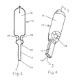
- FIG. 3 illustrates a cross-section of the embodiment of FIG. 4 .
- FIG. 4 illustrates an embodiment wherein a cutting member and a bulb are integral and a constriction zone is found in the bulb.
- FIG. 1 illustrates an embodiment of a gel extractor 10 comprising a hollow cutting member 12 and a squeeze bulb 16.
- Hollow cutting member 12 defines a lumen having a receptacle end defining a sample receptacle 11 and a connector end 13.
- the sample receptacle 11 is shaped to accommodate substantially rectangular shaped gel slices, which is typical of bands of biomolecules obtained by electrophoresis.
- the walls of the sample receptacle taper gradually into a perimeter cutting edge 14 that cleanly cuts gel slices from electrophoretic gels.
- the perimeter cutting edge 14 is between about .005 to .03 inch thickness (0,127 to 0,762 mm).
- a constriction zone 20 is shown as defined by a shoulder 22 at an open end of bulb 16.
- the embodiment in FIG. 3 shows dimples 28 to form constriction zone 20.
- the constriction zone reduces the likelihood that the sample is drawn too far into the extractor.
- bulb 16 is capable of being detached from hollow cutting member 12. While the squeeze bulb is shown to fit into the cutting member, another embodiment comprises a hollow cutting member that is affixed inside of the bulb.
- the gel extractor 10 can be a one-piece device, where the bulb 16 and the hollow cutting member 12 are formed integrally.
- the embodiment of Fig. 4 shows dimples 28 which define an internal constriction zone 20 (see FIG. 3 ).
- the constriction zone can be found in the hollow cutting member, the bulb, or in a transition between the two.
- FIG. 3 provides a cross-sectional view of the integral, one-piece device having the construction zone 20 defined by dimples 28. The width of the constricted passage is variable.
- the constriction may range from about 0.001 to about 0.09 inch (0,0254 to 2,29 mm), preferably about 0.005 to about 0.08 inch (0,127 to 2,03 mm).
- a further embodiment may have a constriction width of between about 0.04 to about 0.07 inch (1,02 to 1,78 mm).
- the constriction zone can be a variety of shapes and sizes, including rectangular, round, square, oval, diamond, triangular or a combination, thereof. Note that cutting edge 14 is not defined by a tapering of the walls in this embodiment.
- the extraction tool described herein To use the extraction tool described herein, one presses the cutting edge into the gel matrix which simultaneously cuts the sample and forces the sample into the receptacle. When the tool is pulled away from the gel matrix, the sample is retained in the receptacle. One does not need to pre-squeeze the bulb, since friction is generally sufficient to hold the sample in the receptacle. However, one may squeeze the bulb slightly prior to forcing the tip into the gel, and release the bulb to create a slight vacuum during or after the cutting edge is pressed into the gel matrix. When the dimples are in the bulb, the slight vacuum can be created by squeezing the bulb at, for example, the dimples. To transfer the sample, the bulb is squeezed to create sufficient air pressure to expel the sample.
- the perimeter cutting edge 14 can be positioned at a variety of angles relative to the gel, including a preferable 90 degree angle where a clean cut is easily achieved.
- the downward movement of the gel extraction device 10 forces the cut gel slice into the sample receptacle which is primarily retained by friction force within receptacle 11.
- gel extractor 10 is lifted away from the remaining gel matrix with the excised gel sample retained in receptacle 11.
- gel extractor 10 is placed over an open container.
- the user squeezes bulb 16 to increase the internal air pressure to expel the sample from sample receptacle 11 in to the container.
- the squeeze bulb returns to its original shape and the extractor may be used to extract another sample.
- use of the extractor to extract multiple samples may cause contamination of the samples.
- another embodiment provides a squeeze bulb that retains the squeezed position after use, and cannot be used more than once.
- Gel extractor 10 does not rely on pressure gradations to retain the gel sample. Retention is, for the most part, achieved through frictional forces between inner walls receptacle 11 and outer walls of the gel slice. Using sharp perimeter cutting edges 14 helps insure that a clean gel sample is achieved and that the gel sample is properly seated within the receptacle. Proper seating maximizes contact points between the gel sample and the walls of the receptacle 11 so that the gel sample is retained until the gel sample transfer process. However, on occasion, a part of the sample may remain outside of the sample receptacle. Generally, this does not present a problem in retaining and transferring the gel sample.
- the gel extraction device 10 perimeter sharp cutting edge 14 is amenable to a wide range of dimensions.
- the dimensions of the device can be varied to accommodate large gel slices.
- the thickness of the cutting edges 14 should not be altered since a clean cut is desirable for all gel slices whether the gel slices are isolated for further analysis of associated biomolecules or for preparative purposes. Nevertheless, the disclosed dimensions merely disclose preferred embodiments, and are not intended to limit the invention to any specified range.
- the cutting edge defines substantially a rectangle.
- additional embodiments include cutting edge that do not define rectangular cross section.
- Examples of cutting cross sections include, but are not limited to substantially oval and substantially circular.
- some preferred embodiments have an about .38 millimeter (mm) to about 6.5 mm width, with an about 2.0 mm to about 100 mm length.
- For the substantially circular cross section some preferred embodiments have an inner diameter of about 1 mm. to about 32 mm.
- the substantially circular cutting edge has a diameter of about 1.5 mm.
- the cross-section can be expressed in surface areas. Some such embodiments have a surface area range of between 1 mm. by 1 mm. to about 32 mm. by 32 mm. It should be apparent that the above dimensions are provided for illustrative purposes, and are not meant to limit the scope of the invention.
- a blow-hole is formed in the hollow cutting member or in the bulb to allow air displaced by the sample to pass out of the extraction device.
- the blow-hole may be covered by, for example a finger, to create a vacuum to assist in retaining the sample in the extraction device.
- the blow-hole has to be covered so that sufficient air pressure can be created by squeezing the squeeze bulb to expel the sample.
- All embodiments of the gel extraction device are preferably made entirely of plastic material, such as, but not limited to polypropylene, polyethylene, polystyrene or a mixture of plastic materials and the preferred manufacturing method is injection molding.
- the squeeze bulb may be made of the same materials as the rest of the extraction device.
- the bulb may be made of other pliable materials such as polyurethane, polyvinylchloride, and latex rubber.
- the type of plastic used need not be the same throughout the device. However, the invention is not limited by the materials disclosed. Any material useful for making the invention is within the scope of the invention.
Landscapes
- Health & Medical Sciences (AREA)
- Life Sciences & Earth Sciences (AREA)
- Molecular Biology (AREA)
- Chemical & Material Sciences (AREA)
- Chemical Kinetics & Catalysis (AREA)
- Electrochemistry (AREA)
- Physics & Mathematics (AREA)
- Analytical Chemistry (AREA)
- Biochemistry (AREA)
- General Health & Medical Sciences (AREA)
- General Physics & Mathematics (AREA)
- Immunology (AREA)
- Pathology (AREA)
- Investigating Or Analysing Biological Materials (AREA)
- Sampling And Sample Adjustment (AREA)
Claims (12)
- Vorrichtung zur Extraktion von Gelproben (10), bestehend aus:einem hohlen Schneideelement (12), das eine Steckverbindung (13) an einem Ende und ein Schneidwerkzeug am anderen Ende aufweist, welche die beiden Enden eines Lumens definieren, wobei das Lumen am Schneideende einen Probebehälter (11) definiert, der in einer umlaufenden Schneidekante (14) endet;einem an der Steckverbindung (13) angeordneten Gummibalg (16) undeiner Engstelle (20) zwischen der Schneidekante (14) und dem Gummibalg (16), wobei die Engstelle den Durchgang zwischen dem Behälter (11) und dem Gummibalg (16) beschränkt.
- Die Vorrichtung zur Extraktion von Gelproben (10) nach Anspruch 1, wobei die Schneidekante (14) zwischen 0,127 mm und 0,762 mm Dicke beträgt.
- Die Vorrichtung zur Extraktion von Gelproben (10) nach Anspruch 1, wobei der besagte Behälter (11) rechteckig ist und ein zugespitztes Schneideende aufweist, das sich formt, wenn sich mindestens zwei gegenüberliegende Seiten langsam aufeinander zu bewegen, bis die Seiten die Schneidekante bilden.
- Die Vorrichtung zur Extraktion von Gelproben (10) nach Anspruch 1, wobei der Behälter (11) mit der Schneidekante (14) vom Schneideelement (12) abgetrennt werden kann.
- Die Vorrichtung zur Extraktion von Gelproben (10) nach Anspruch 1, wobei der Gummibalg (16) mit dem hohlen Schneideelement (12) fest integriert ist.
- Die Vorrichtung zur Extraktion von Gelproben (10) nach Anspruch 1, wobei der Gummibalg (16) entweder durch Einfügen des Gummibalgs (16) in die Steckverbindung (13) oder durch Einfügen der Steckverbindung in den Gummibalg (16) befestigt ist.
- Die Vorrichtung zur Extraktion von Gelproben (10) nach Anspruch 1, wobei der Gummibalg (16) durch Einfügen der Steckverbindung (13) in den Gummibalg (16) befestigt ist.
- Die Vorrichtung zur Extraktion von Gelproben (10) nach Anspruch 1, wobei die Engstelle (20) entweder im hohlen Schneideelement (12) oder im Gummibalg (16) angeordnet ist.
- Die Vorrichtung zur Extraktion von Gelproben (10) nach Anspruch 1, wobei der besagte Behälter (11) einen Querschnitt aufweist, der im Wesentlichen entweder ein Rechteck oder ein Oval darstellt.
- Die Vorrichtung zur Extraktion von Gelproben (10) nach Anspruch 9, wobei die Schneidekante (14) einen Querschnitt definiert, der im Wesentlichen ein Rechteck darstellt.
- Die Vorrichtung zur Extraktion von Gelproben (10) nach Anspruch 9, wobei der Gummibalg (16) entweder mit dem hohlen Schneideelement (12) fest integriert oder vom hohlen Schneideelement (12) abtrennbar ist.
- Ein Verfahren zur Extraktion von Gelproben aus einer Elektrophorese-Gelmatrix mit einer Vorrichtung zur Extraktion von Gelproben (10) nach Anspruch 1, wobei das Verfahren aus den folgenden Schritten besteht:Andrücken der umlaufenden Schneidekante (14) an die Gelmatrix, um der Gelmatrix eine Probe zu entnehmen und in den Probenbehälter (11) zu forcieren;Abziehen der Vorrichtung zur Extraktion von Gelproben (10) von der Gelmatrix, um die Gelprobe in den Probenbehälter (11) einzuziehen, undAndrücken des Gummibalgs (16), um die Gelprobe aus dem Probenbehälter (11) zu entnehmen.
Applications Claiming Priority (1)
| Application Number | Priority Date | Filing Date | Title |
|---|---|---|---|
| PCT/US2005/046202 WO2007073367A1 (en) | 2005-12-20 | 2005-12-20 | Tool for extracting electrophoretic sample |
Publications (3)
| Publication Number | Publication Date |
|---|---|
| EP1963834A1 EP1963834A1 (de) | 2008-09-03 |
| EP1963834A4 EP1963834A4 (de) | 2012-08-29 |
| EP1963834B1 true EP1963834B1 (de) | 2013-10-02 |
Family
ID=38188970
Family Applications (1)
| Application Number | Title | Priority Date | Filing Date |
|---|---|---|---|
| EP05854849.6A Expired - Lifetime EP1963834B1 (de) | 2005-12-20 | 2005-12-20 | Werkzeug zur extraktion einer elektrophoreseprobe |
Country Status (3)
| Country | Link |
|---|---|
| US (1) | US8163153B2 (de) |
| EP (1) | EP1963834B1 (de) |
| WO (1) | WO2007073367A1 (de) |
Families Citing this family (6)
| Publication number | Priority date | Publication date | Assignee | Title |
|---|---|---|---|---|
| BR112015001460A2 (pt) * | 2012-07-24 | 2017-07-04 | Cryoxtract Instr Llc | sonda de escavação, sistemas para colher núcleo de amostras congelados de uma pluralidade de amostras congeladas, para coletar alíquotas congeladas de amostras biológicas congeladas contidas em contêineres de amostras, para armazenar amostras de tecido congeladas, métodos de colher um núcleo de amostra congelada de uma amostra congelada, para aumentar a probabilidade de um operador usar apenas as sondas de escavação, para preparar e amostrar uma amostra de tecido em um contêiner de amostra de tecido, e de armazenamento de uma amostra de tecido, dispositivo portátil de escavação, bandeja, contêiner de amostra de tecido, kit para preparação de u,a a,ostra de tecido, transporte de tecido para suportar a amostra de tecido, e, combinação de transporte de tecido e dispositivo de escavação. |
| CN102839113B (zh) * | 2012-09-12 | 2014-01-01 | 北京工业大学 | 可调宽度式快速切胶装置 |
| USD747634S1 (en) * | 2014-04-15 | 2016-01-19 | Japan Aviation Electronics Industry, Limited | Guide instrument for optical connector |
| WO2015186673A1 (ja) * | 2014-06-04 | 2015-12-10 | シャープ株式会社 | 媒体切り出し器具、媒体切り出し装置および媒体切り出し方法 |
| US20180136164A1 (en) * | 2016-11-14 | 2018-05-17 | SeqMatic, LLC | Systems and methods to extract target material from a gel |
| CN107064275B (zh) * | 2017-03-15 | 2019-04-05 | 东北农业大学 | 大豆蚜虫分子研究用防eb染液致癌伤人的电泳胶片移取装置 |
Family Cites Families (40)
| Publication number | Priority date | Publication date | Assignee | Title |
|---|---|---|---|---|
| US1451610A (en) | 1921-09-15 | 1923-04-10 | Gestas Isidore | Boring machine for paper |
| US2237213A (en) | 1939-05-31 | 1941-04-01 | Ralph F Brown | Pipette |
| US2358936A (en) | 1941-05-27 | 1944-09-26 | Clay Adams Co Inc | Pipette |
| US2728232A (en) | 1953-07-13 | 1955-12-27 | Richard L Costello | Pipette filling bulb |
| US3039500A (en) | 1959-01-22 | 1962-06-19 | Goldberg Moshe Levy | Pipette filling and liquid dispensing device |
| US3233785A (en) | 1962-09-13 | 1966-02-08 | Dade Reagents Inc | Rinsing pipette |
| US3757585A (en) * | 1968-08-16 | 1973-09-11 | Heller Labor | Pipette apparatus |
| US3732734A (en) * | 1972-05-25 | 1973-05-15 | Centaur Chemical Co | Micropipette with disposable tips |
| US3949471A (en) | 1972-10-03 | 1976-04-13 | Cawley Leo P | Process and means for gel cutting |
| US3839183A (en) | 1973-06-15 | 1974-10-01 | Beckman Instruments Inc | Electrophoresis sample applicator |
| US3881527A (en) * | 1974-01-03 | 1975-05-06 | Justin Joel Shapiro | Bulb-operated pipet |
| US4010543A (en) | 1975-10-28 | 1977-03-08 | Nusbaum Max J | Hole cutting apparatus |
| US4078588A (en) * | 1976-12-13 | 1978-03-14 | Jack Andrew Hardwick | Suction device for collecting mineral samples |
| US4316465A (en) | 1979-03-30 | 1982-02-23 | Dotson Robert S Jun | Ophthalmic handpiece with pneumatically operated cutter |
| FR2521162A1 (fr) | 1982-02-09 | 1983-08-12 | Rhone Poulenc Sa | Trepan semi-automatique pour realiser des cavites dans une couche de matiere gelifiee |
| FR2563343B1 (fr) | 1984-04-19 | 1986-06-13 | Rhone Poulenc Sante | Dispositif pour effectuer des prelevements dans des milieux semi-solides |
| US4696298A (en) | 1985-11-19 | 1987-09-29 | Storz Instrument Company | Vitrectomy cutting mechanism |
| US5032343A (en) | 1986-08-11 | 1991-07-16 | Multi-Technology, Inc | Method for producing medical micro pipette tips for difficult to reach places |
| US4707337A (en) * | 1986-08-11 | 1987-11-17 | Multi-Technology, Inc. | Medical micro pipette tips for difficult to reach places and related methods |
| US4779768A (en) | 1987-07-24 | 1988-10-25 | St. Amand Manufacturing Co., Inc. | Volumetric dispensing pipette |
| US5125544A (en) | 1989-12-11 | 1992-06-30 | Helena Laboratories Corporation | Pipette pump |
| US5217591A (en) | 1990-05-14 | 1993-06-08 | Labintelligence, Inc. | Gel electrophoresis sample applicator/retriever |
| US5238651A (en) | 1990-07-23 | 1993-08-24 | New York University | Gel plates, equipment and kits for combined electrophoretic-immunoelectrophoretic analysis |
| GB2250014B (en) | 1990-11-16 | 1994-02-16 | Kodak Ltd | Sampling devices |
| US5343771A (en) | 1992-07-20 | 1994-09-06 | En Chem, Inc. | Tool for sampling soil containing volatile organic compound |
| US5476017A (en) | 1993-10-15 | 1995-12-19 | Acutrol Co. | Unit dose bulk material sampling apparatus |
| US5413115A (en) | 1993-12-29 | 1995-05-09 | Baldwin; James R. | Biopsy syringe with slide valve |
| US5538614A (en) * | 1994-08-17 | 1996-07-23 | Han; Dawn D. | Macromolecule recovery cassette |
| JP3381484B2 (ja) | 1995-04-26 | 2003-02-24 | 株式会社島津製作所 | ゲル電気泳動によるサンプル分取装置 |
| US5587062A (en) * | 1996-01-24 | 1996-12-24 | Shimadzu Corporation | Sample collecting apparatus by gel electrophoresis |
| GB9624927D0 (en) | 1996-11-29 | 1997-01-15 | Oxford Glycosciences Uk Ltd | Gels and their use |
| US5775546A (en) * | 1997-05-01 | 1998-07-07 | Comar, Inc. | Dispensing bulb |
| US6149787A (en) * | 1998-10-14 | 2000-11-21 | Caliper Technologies Corp. | External material accession systems and methods |
| US6342143B1 (en) | 2000-01-06 | 2002-01-29 | Carnegie Mellon University | Cutting tool for multiple sample retrieval from gelatinous material |
| US6393926B1 (en) | 2000-05-19 | 2002-05-28 | Accutrol Co., Inc. | Front-loading precision material sampler with interchangeable retracting chamber |
| US6565728B1 (en) * | 2000-06-08 | 2003-05-20 | Elchrom Scientific | Gel cutting and recovering device |
| GB0016010D0 (en) | 2000-06-30 | 2000-08-23 | Amersham Pharm Biotech Ab | Spot picker device and method for picking gel plugs |
| JP4004240B2 (ja) | 2001-04-13 | 2007-11-07 | 独立行政法人科学技術振興機構 | 乾燥電気泳動用ゲルカッター |
| US6702990B1 (en) | 2002-02-05 | 2004-03-09 | The Gel Company | Spot picker |
| US7247275B2 (en) | 2004-06-21 | 2007-07-24 | Jeremy Scot Caldwell | Gel extraction device |
-
2005
- 2005-12-20 EP EP05854849.6A patent/EP1963834B1/de not_active Expired - Lifetime
- 2005-12-20 US US12/158,208 patent/US8163153B2/en active Active
- 2005-12-20 WO PCT/US2005/046202 patent/WO2007073367A1/en not_active Ceased
Also Published As
| Publication number | Publication date |
|---|---|
| WO2007073367A1 (en) | 2007-06-28 |
| EP1963834A4 (de) | 2012-08-29 |
| US20090286326A1 (en) | 2009-11-19 |
| EP1963834A1 (de) | 2008-09-03 |
| US8163153B2 (en) | 2012-04-24 |
Similar Documents
| Publication | Publication Date | Title |
|---|---|---|
| US7413908B2 (en) | Gel extraction device | |
| DE60126761T2 (de) | Gelschneide- und rückgewinnungsvorrichtung | |
| US6200275B1 (en) | Sample collection device with extraction sleeve | |
| US9072499B2 (en) | Sample collection tool | |
| CA2694786C (en) | Apparatus and process for removing substances from pre-filled containers | |
| EP0126390B1 (de) | Flüssigkeitsübertragungsverfahren und Vorrichtung | |
| US6821788B2 (en) | Diagnostic testing device and method of use thereof | |
| USRE42606E1 (en) | Low insertion force tip/mandrel | |
| US20050252820A1 (en) | Sampling kits, devices and uses thereof | |
| EP1963834B1 (de) | Werkzeug zur extraktion einer elektrophoreseprobe | |
| EP2075567A2 (de) | Küvette und Verfahren und Formwerkzeug zur Herstellung davon | |
| DE19714987C1 (de) | Vorrichtung zur Isolation von Partikeln, insbesondere von Zellen | |
| KR20150112216A (ko) | 분리가능한 이중 샘플 튜브 | |
| US10183410B2 (en) | Vegetable stick maker | |
| JP2994675B2 (ja) | 棒組立体 | |
| JP2007209360A (ja) | 試料採取具 | |
| CN109116010B (zh) | 用于血液外泌体采集的试管及外泌体分离方法 | |
| CN220932421U (zh) | 一种琼脂培养基打孔提取装置 | |
| EP4689052A1 (de) | Flüssigkeitshandhabungsvorrichtung zum scheren und filtern von biologischem material | |
| CN204848894U (zh) | 干细胞制剂制备装置 | |
| EP2715309B1 (de) | Vorrichtung zur entnahme einer materialprobe aus einem block aus diesem material | |
| KR101339770B1 (ko) | 겔밴드 추출 기구 및 이를 이용한 겔밴드 추출 방법 | |
| JPH0657427U (ja) | ピペットチップ | |
| CN106399100A (zh) | 干细胞制剂制备装置 |
Legal Events
| Date | Code | Title | Description |
|---|---|---|---|
| PUAI | Public reference made under article 153(3) epc to a published international application that has entered the european phase |
Free format text: ORIGINAL CODE: 0009012 |
|
| 17P | Request for examination filed |
Effective date: 20080707 |
|
| AK | Designated contracting states |
Kind code of ref document: A1 Designated state(s): AT BE BG CH CY CZ DE DK EE ES FI FR GB GR HU IE IS IT LI LT LU LV MC NL PL PT RO SE SI SK TR |
|
| DAX | Request for extension of the european patent (deleted) | ||
| A4 | Supplementary search report drawn up and despatched |
Effective date: 20120731 |
|
| RIC1 | Information provided on ipc code assigned before grant |
Ipc: B01L 3/02 20060101ALI20120725BHEP Ipc: G01N 27/453 20060101ALI20120725BHEP Ipc: G01N 27/447 20060101AFI20120725BHEP Ipc: G01N 1/14 20060101ALI20120725BHEP |
|
| GRAP | Despatch of communication of intention to grant a patent |
Free format text: ORIGINAL CODE: EPIDOSNIGR1 |
|
| INTG | Intention to grant announced |
Effective date: 20130415 |
|
| GRAS | Grant fee paid |
Free format text: ORIGINAL CODE: EPIDOSNIGR3 |
|
| GRAA | (expected) grant |
Free format text: ORIGINAL CODE: 0009210 |
|
| AK | Designated contracting states |
Kind code of ref document: B1 Designated state(s): AT BE BG CH CY CZ DE DK EE ES FI FR GB GR HU IE IS IT LI LT LU LV MC NL PL PT RO SE SI SK TR |
|
| REG | Reference to a national code |
Ref country code: GB Ref legal event code: FG4D |
|
| REG | Reference to a national code |
Ref country code: AT Ref legal event code: REF Ref document number: 634833 Country of ref document: AT Kind code of ref document: T Effective date: 20131015 Ref country code: CH Ref legal event code: EP |
|
| REG | Reference to a national code |
Ref country code: IE Ref legal event code: FG4D |
|
| REG | Reference to a national code |
Ref country code: DE Ref legal event code: R096 Ref document number: 602005041419 Country of ref document: DE Effective date: 20131128 |
|
| REG | Reference to a national code |
Ref country code: AT Ref legal event code: MK05 Ref document number: 634833 Country of ref document: AT Kind code of ref document: T Effective date: 20131002 |
|
| REG | Reference to a national code |
Ref country code: NL Ref legal event code: VDEP Effective date: 20131002 |
|
| PG25 | Lapsed in a contracting state [announced via postgrant information from national office to epo] |
Ref country code: SI Free format text: LAPSE BECAUSE OF FAILURE TO SUBMIT A TRANSLATION OF THE DESCRIPTION OR TO PAY THE FEE WITHIN THE PRESCRIBED TIME-LIMIT Effective date: 20131002 |
|
| REG | Reference to a national code |
Ref country code: LT Ref legal event code: MG4D |
|
| PG25 | Lapsed in a contracting state [announced via postgrant information from national office to epo] |
Ref country code: SE Free format text: LAPSE BECAUSE OF FAILURE TO SUBMIT A TRANSLATION OF THE DESCRIPTION OR TO PAY THE FEE WITHIN THE PRESCRIBED TIME-LIMIT Effective date: 20131002 Ref country code: IS Free format text: LAPSE BECAUSE OF FAILURE TO SUBMIT A TRANSLATION OF THE DESCRIPTION OR TO PAY THE FEE WITHIN THE PRESCRIBED TIME-LIMIT Effective date: 20140202 Ref country code: NL Free format text: LAPSE BECAUSE OF FAILURE TO SUBMIT A TRANSLATION OF THE DESCRIPTION OR TO PAY THE FEE WITHIN THE PRESCRIBED TIME-LIMIT Effective date: 20131002 Ref country code: LT Free format text: LAPSE BECAUSE OF FAILURE TO SUBMIT A TRANSLATION OF THE DESCRIPTION OR TO PAY THE FEE WITHIN THE PRESCRIBED TIME-LIMIT Effective date: 20131002 Ref country code: BE Free format text: LAPSE BECAUSE OF FAILURE TO SUBMIT A TRANSLATION OF THE DESCRIPTION OR TO PAY THE FEE WITHIN THE PRESCRIBED TIME-LIMIT Effective date: 20131002 Ref country code: FI Free format text: LAPSE BECAUSE OF FAILURE TO SUBMIT A TRANSLATION OF THE DESCRIPTION OR TO PAY THE FEE WITHIN THE PRESCRIBED TIME-LIMIT Effective date: 20131002 Ref country code: CZ Free format text: LAPSE BECAUSE OF FAILURE TO SUBMIT A TRANSLATION OF THE DESCRIPTION OR TO PAY THE FEE WITHIN THE PRESCRIBED TIME-LIMIT Effective date: 20131002 |
|
| PG25 | Lapsed in a contracting state [announced via postgrant information from national office to epo] |
Ref country code: ES Free format text: LAPSE BECAUSE OF FAILURE TO SUBMIT A TRANSLATION OF THE DESCRIPTION OR TO PAY THE FEE WITHIN THE PRESCRIBED TIME-LIMIT Effective date: 20131002 Ref country code: AT Free format text: LAPSE BECAUSE OF FAILURE TO SUBMIT A TRANSLATION OF THE DESCRIPTION OR TO PAY THE FEE WITHIN THE PRESCRIBED TIME-LIMIT Effective date: 20131002 Ref country code: CY Free format text: LAPSE BECAUSE OF FAILURE TO SUBMIT A TRANSLATION OF THE DESCRIPTION OR TO PAY THE FEE WITHIN THE PRESCRIBED TIME-LIMIT Effective date: 20131002 Ref country code: PL Free format text: LAPSE BECAUSE OF FAILURE TO SUBMIT A TRANSLATION OF THE DESCRIPTION OR TO PAY THE FEE WITHIN THE PRESCRIBED TIME-LIMIT Effective date: 20131002 Ref country code: LV Free format text: LAPSE BECAUSE OF FAILURE TO SUBMIT A TRANSLATION OF THE DESCRIPTION OR TO PAY THE FEE WITHIN THE PRESCRIBED TIME-LIMIT Effective date: 20131002 |
|
| PG25 | Lapsed in a contracting state [announced via postgrant information from national office to epo] |
Ref country code: PT Free format text: LAPSE BECAUSE OF FAILURE TO SUBMIT A TRANSLATION OF THE DESCRIPTION OR TO PAY THE FEE WITHIN THE PRESCRIBED TIME-LIMIT Effective date: 20140203 |
|
| REG | Reference to a national code |
Ref country code: DE Ref legal event code: R097 Ref document number: 602005041419 Country of ref document: DE |
|
| PG25 | Lapsed in a contracting state [announced via postgrant information from national office to epo] |
Ref country code: EE Free format text: LAPSE BECAUSE OF FAILURE TO SUBMIT A TRANSLATION OF THE DESCRIPTION OR TO PAY THE FEE WITHIN THE PRESCRIBED TIME-LIMIT Effective date: 20131002 |
|
| REG | Reference to a national code |
Ref country code: CH Ref legal event code: PL |
|
| PLBE | No opposition filed within time limit |
Free format text: ORIGINAL CODE: 0009261 |
|
| STAA | Information on the status of an ep patent application or granted ep patent |
Free format text: STATUS: NO OPPOSITION FILED WITHIN TIME LIMIT |
|
| PG25 | Lapsed in a contracting state [announced via postgrant information from national office to epo] |
Ref country code: SK Free format text: LAPSE BECAUSE OF FAILURE TO SUBMIT A TRANSLATION OF THE DESCRIPTION OR TO PAY THE FEE WITHIN THE PRESCRIBED TIME-LIMIT Effective date: 20131002 Ref country code: IT Free format text: LAPSE BECAUSE OF FAILURE TO SUBMIT A TRANSLATION OF THE DESCRIPTION OR TO PAY THE FEE WITHIN THE PRESCRIBED TIME-LIMIT Effective date: 20131002 Ref country code: RO Free format text: LAPSE BECAUSE OF FAILURE TO SUBMIT A TRANSLATION OF THE DESCRIPTION OR TO PAY THE FEE WITHIN THE PRESCRIBED TIME-LIMIT Effective date: 20131002 Ref country code: MC Free format text: LAPSE BECAUSE OF FAILURE TO SUBMIT A TRANSLATION OF THE DESCRIPTION OR TO PAY THE FEE WITHIN THE PRESCRIBED TIME-LIMIT Effective date: 20131002 Ref country code: LU Free format text: LAPSE BECAUSE OF FAILURE TO SUBMIT A TRANSLATION OF THE DESCRIPTION OR TO PAY THE FEE WITHIN THE PRESCRIBED TIME-LIMIT Effective date: 20131220 |
|
| 26N | No opposition filed |
Effective date: 20140703 |
|
| REG | Reference to a national code |
Ref country code: IE Ref legal event code: MM4A |
|
| PG25 | Lapsed in a contracting state [announced via postgrant information from national office to epo] |
Ref country code: DK Free format text: LAPSE BECAUSE OF FAILURE TO SUBMIT A TRANSLATION OF THE DESCRIPTION OR TO PAY THE FEE WITHIN THE PRESCRIBED TIME-LIMIT Effective date: 20131002 |
|
| REG | Reference to a national code |
Ref country code: DE Ref legal event code: R097 Ref document number: 602005041419 Country of ref document: DE Effective date: 20140703 |
|
| PG25 | Lapsed in a contracting state [announced via postgrant information from national office to epo] |
Ref country code: LI Free format text: LAPSE BECAUSE OF NON-PAYMENT OF DUE FEES Effective date: 20131231 Ref country code: CH Free format text: LAPSE BECAUSE OF NON-PAYMENT OF DUE FEES Effective date: 20131231 Ref country code: IE Free format text: LAPSE BECAUSE OF NON-PAYMENT OF DUE FEES Effective date: 20131220 |
|
| PG25 | Lapsed in a contracting state [announced via postgrant information from national office to epo] |
Ref country code: TR Free format text: LAPSE BECAUSE OF FAILURE TO SUBMIT A TRANSLATION OF THE DESCRIPTION OR TO PAY THE FEE WITHIN THE PRESCRIBED TIME-LIMIT Effective date: 20131002 |
|
| PG25 | Lapsed in a contracting state [announced via postgrant information from national office to epo] |
Ref country code: BG Free format text: LAPSE BECAUSE OF FAILURE TO SUBMIT A TRANSLATION OF THE DESCRIPTION OR TO PAY THE FEE WITHIN THE PRESCRIBED TIME-LIMIT Effective date: 20131002 Ref country code: HU Free format text: LAPSE BECAUSE OF FAILURE TO SUBMIT A TRANSLATION OF THE DESCRIPTION OR TO PAY THE FEE WITHIN THE PRESCRIBED TIME-LIMIT; INVALID AB INITIO Effective date: 20051220 |
|
| PG25 | Lapsed in a contracting state [announced via postgrant information from national office to epo] |
Ref country code: GR Free format text: LAPSE BECAUSE OF NON-PAYMENT OF DUE FEES Effective date: 20131002 |
|
| REG | Reference to a national code |
Ref country code: FR Ref legal event code: PLFP Year of fee payment: 11 |
|
| PG25 | Lapsed in a contracting state [announced via postgrant information from national office to epo] |
Ref country code: GR Free format text: LAPSE BECAUSE OF FAILURE TO SUBMIT A TRANSLATION OF THE DESCRIPTION OR TO PAY THE FEE WITHIN THE PRESCRIBED TIME-LIMIT Effective date: 20140103 |
|
| REG | Reference to a national code |
Ref country code: FR Ref legal event code: PLFP Year of fee payment: 12 |
|
| REG | Reference to a national code |
Ref country code: FR Ref legal event code: PLFP Year of fee payment: 13 |
|
| PGFP | Annual fee paid to national office [announced via postgrant information from national office to epo] |
Ref country code: FR Payment date: 20201230 Year of fee payment: 16 Ref country code: GB Payment date: 20201230 Year of fee payment: 16 |
|
| GBPC | Gb: european patent ceased through non-payment of renewal fee |
Effective date: 20211220 |
|
| PG25 | Lapsed in a contracting state [announced via postgrant information from national office to epo] |
Ref country code: GB Free format text: LAPSE BECAUSE OF NON-PAYMENT OF DUE FEES Effective date: 20211220 |
|
| PG25 | Lapsed in a contracting state [announced via postgrant information from national office to epo] |
Ref country code: FR Free format text: LAPSE BECAUSE OF NON-PAYMENT OF DUE FEES Effective date: 20211231 |
|
| PGFP | Annual fee paid to national office [announced via postgrant information from national office to epo] |
Ref country code: DE Payment date: 20231229 Year of fee payment: 19 |
|
| REG | Reference to a national code |
Ref country code: DE Ref legal event code: R119 Ref document number: 602005041419 Country of ref document: DE |
|
| PG25 | Lapsed in a contracting state [announced via postgrant information from national office to epo] |
Ref country code: DE Free format text: LAPSE BECAUSE OF NON-PAYMENT OF DUE FEES Effective date: 20250701 |