EP1964308B1 - Leistungsmanagment in einem system zur stromversorgung über die kommunikationsverbindung - Google Patents
Leistungsmanagment in einem system zur stromversorgung über die kommunikationsverbindung Download PDFInfo
- Publication number
- EP1964308B1 EP1964308B1 EP06836221A EP06836221A EP1964308B1 EP 1964308 B1 EP1964308 B1 EP 1964308B1 EP 06836221 A EP06836221 A EP 06836221A EP 06836221 A EP06836221 A EP 06836221A EP 1964308 B1 EP1964308 B1 EP 1964308B1
- Authority
- EP
- European Patent Office
- Prior art keywords
- power
- powered device
- power supply
- allocation
- priority
- Prior art date
- Legal status (The legal status is an assumption and is not a legal conclusion. Google has not performed a legal analysis and makes no representation as to the accuracy of the status listed.)
- Active
Links
- 230000007246 mechanism Effects 0.000 title claims description 14
- 238000004891 communication Methods 0.000 title claims description 12
- 238000000034 method Methods 0.000 claims description 19
- 230000004048 modification Effects 0.000 claims description 7
- 238000012986 modification Methods 0.000 claims description 7
- 230000004044 response Effects 0.000 claims description 3
- 238000007726 management method Methods 0.000 description 16
- 238000001514 detection method Methods 0.000 description 15
- 230000008859 change Effects 0.000 description 5
- 238000010586 diagram Methods 0.000 description 3
- 230000009286 beneficial effect Effects 0.000 description 2
- 230000005540 biological transmission Effects 0.000 description 2
- 238000001816 cooling Methods 0.000 description 2
- 238000012358 sourcing Methods 0.000 description 2
- 238000004378 air conditioning Methods 0.000 description 1
- 238000006243 chemical reaction Methods 0.000 description 1
- 238000013461 design Methods 0.000 description 1
- 238000005516 engineering process Methods 0.000 description 1
- 238000003032 molecular docking Methods 0.000 description 1
- 238000012544 monitoring process Methods 0.000 description 1
- 230000006855 networking Effects 0.000 description 1
- 238000011176 pooling Methods 0.000 description 1
- 239000000523 sample Substances 0.000 description 1
Images


Classifications
-
- H—ELECTRICITY
- H04—ELECTRIC COMMUNICATION TECHNIQUE
- H04L—TRANSMISSION OF DIGITAL INFORMATION, e.g. TELEGRAPHIC COMMUNICATION
- H04L12/00—Data switching networks
- H04L12/02—Details
- H04L12/10—Current supply arrangements
Definitions
- This disclosure relates to power supply systems, and more particularly, to circuitries and methodologies for managing power in a Power over Ethernet (PoE) system.
- PoE Power over Ethernet
- Ethernet has become the most commonly used method for local area networking.
- IEEE 802.3 group the originator of the Ethernet standard, has developed an extension to the standard, known as IEEE 802.3af, that defines supplying power over Ethernet cabling.
- IEEE 802.3af defines a Power over Ethernet (PoE) system that involves delivering power over unshielded twisted-pair wiring from Power Sourcing Equipment (PSE) to a Powered Device (PD) located at opposite sides of a link.
- PSE Power Sourcing Equipment
- PD Powered Device
- network devices such as IP phones, wireless LAN access points, personal computers and Web cameras, have required two connections: one to a LAN and another to a power supply system.
- the PoE system eliminates the need for additional outlets and wiring to supply power to network devices. Instead, power is supplied over Ethernet cabling used for data transmission.
- PSE and PD are non-data entities allowing network devices to supply and draw power using the same generic cabling as is used for data transmission.
- a PSE is the equipment electrically specified at the point of the physical connection to the cabling, that provides the power to a link.
- a PSE is typically associated with an Ethernet switch, router, hub or other network switching equipment or midspan device.
- a PD is a device that is either drawing power or requesting power. PDs may be associated with such devices as digital IP telephones, wireless network access points, PDA or notebook computer docking stations, cell phone chargers and HVAC thermostats.
- PSE's main functions are to search the link for a PD requesting power, optionally classify the PD, supply power to the link if a PD is detected, monitor the power on the link, and disconnect power when it is no longer requested or required.
- a PD participates in the PD detection procedure by presenting detection and classification signatures to request power and indicate its power level class.
- the PD detection signature has electrical characteristics measured by the PSE.
- the PD has an option of presenting a classification signature to the PSE to indicate how much power it will draw when powered up. Based on the determined class of the PD, the PSE applies the required power to the PD.
- US Patent No: 6,473,608 B1 discloses a power supply distributor operative to provide at least some operating power to at least some of a plurality of nodes via a communication cabling.
- US Patent Publication No: 2005/080516 A1 discloses a Power over ethernet switch node for use in power pooling
- a power supply system comprises multiple power supply ports for providing power to respective powered devices via multiple communication links.
- a power-in-use bus shared by the multiple power supply ports is configured for receiving a power-in-use signal representing total amount of power being used by the powered devices.
- Multiple port control circuits associated with the power supply ports are responsive to the power-in-use signal for controlling power supply to the respective powered devices.
- a port control circuit may remove power from the respective port when the power-in-use signal exceeds a preset usage threshold level.
- the power may be managed based on priorities of the powered devices so as to remove power supplied to a lower priority powered device before removing power supplied to a higher priority powered device.
- a port control circuit may deny a request for power from a respective powered device when the power-in-use signal exceeds a preset usage threshold level.
- the system further may, comprise a power allocation bus shared by the multiple power supply ports and configured for receiving a power allocation signal representing a total amount of power allocated for the powered devices.
- the ports control circuits may be responsive to the power allocation signal for controlling power supply to the respective powered devices.
- a port control circuit may remove power supplied to a respective powered device when the power allocation signal exceeds a preset allocation threshold level. Power supplied to a lower priority powered device may be removed before removing power from a higher priority powered device.
- a port control circuit may deny a request for power from the respective powered device when the power allocation signal exceeds a preset allocation threshold level.
- the power-in-use bus may be coupled to a power-in-use impedance common for the multiple power supply ports.
- the power allocation bus may be coupled to a power allocation impedance common for the multiple power supply ports.
- a value of the power allocation impedance may be set smaller than the value of the power-in-use impedance.
- a signal modification mechanism may be provided for modifying the power-in-use signal and/or the power allocation signal in response to an event.
- the power-in-use signal and/or the power allocation signal may be changed to effectively change power available from the power supply system.
- a PoE system may comprise multiple PoE ports for supplying power to respective powered devices.
- the ports may be assigned with priorities corresponding to priorities of the respective powered devices.
- a power indication bus shared by the multiple PoE ports may be configured to receive a power indication signal indicating total power allocated to or used by the powered devices.
- Multiple port control circuits associated with the multiple power supply ports may be responsive to the power indication signal for controlling power supply to the respective powered devices in accordance with the priorities of the powered devices.
- the power indication signal may include a power-in-use signal representing total power being used by the powered devices, and/or a power allocation signal representing a total power allocated to the powered devices.
- the following steps are carried out for supplying power from multiple power supply ports to respective powered devices over communication links:
- the method may further include the steps of:
- the following steps are carried out for supplying power from multiple power supply ports to respective powered devices over communication links:
- the method further may comprise the steps of:
- the power may be removed after expiration of a time interval corresponding to the priority of the powered device.
- the present disclosure will be made using the example of a power supply device in a Power over Ethernet (PoE) system. It will become apparent, however, that the concepts described herein are applicable to any power supply system for providing power to multiple loads.
- the system of the present disclosure may be provided in a local area network (LAN) having a plurality of nodes, a network hub and communication cabling connecting the nodes to the network hub for providing data communications.
- the network hub may include a power supply device for providing power to multiple loads over the communication cabling.
- the power supply device may have a power management mechanism of the present disclosure.
- FIG. 1 shows a simplified block-diagram illustrating a PoE system 10 including Power Sourcing Equipment (PSE) 12 having multiple PoE ports 1 to 4 connectable to Powered Devices (PD1 to PD4) via respective links, each of which may be provided using 2 or 4 sets of twisted pairs within an Ethernet cable.
- PSE Power Sourcing Equipment
- FIG. 1 shows four ports of the PSE 12, one skilled in the art would realize that any number of ports may be provided.
- the PSE 12 may be provided based on one or more PSE chips having multiple output ports.
- the PSE 12 may interact with each PD in accordance with the IEEE 802.3af standard.
- the PSE 12 and the PD participate in the PD detection procedure, during which the PSE 12 probes a link to detect the PD. If the PD is detected, the PSE 12 checks the PD detection signature to determine whether it is valid or non-valid.
- the valid and non-valid detection signatures are defined in the IEEE 802.3af standard. While the valid PD detection signature indicates that the PD is in a state where it will accept power, the non-valid PD detection signature indicates that the PD is in a state where it will not accept power.
- the PD has an option of presenting a classification signature to the PSE to indicate how much power it will draw when powered up. For example, a PD may be classified as class 0 to class 4. Based on the determined class of the PD, the PSE applies the required power to the PD.
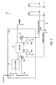
- a power management mechanism 100 of the present disclosure includes a single power allocation bus (PAB) 102 and a single power-in-use bus (PIB) 104 shared by multiple PSE channels PSE-1, PSE-2, ..., PSE-N.
- PSE channels are associated with the respective PoE port of the PSE 12.
- PSE channels may be provided on a PSE chip. Alternatively, each PSE channel may be provided on a separate chip.
- the PAB 102 is used for determining whether power allocated to PDs does not exceed the maximum power available from the multi-channel power supply system.
- the PIB 104 allows the power management mechanism 100 to monitor actual power being used by PDs.
- Each of the PSE channels PSE-1, PSE-2, ..., PSE-N may include a port controller 110, a bus logic 112, current sources 114 and 116, comparators 118 and 120, a switching device 122, a sense resistor Rs, and a priority resistor Rpriority.
- the port controller 110 may control PoE operations associated with the respective PoE port.
- the port controller 110 controls switching of the switching device 122, such as a MOSFET or a bipolar transistor, to supply power to the respective PoE port or to remove power supplied to this port.
- the port controller may support detection and classification procedure prescribed by the IEEE 802.3af standard.
- a common PSE controller may control PoE operations for several PSE channels.
- the bus logic 112 may support interface of the respective PSE channel to the PAB 102 and PIB 104.
- Current sources 114 and 116 may produce PAB and PIB currents placed by the respective PSE channel onto the PAB 102 and PIB 104.
- the PAB current represents power demanded by a PD linked to the respective PSE channel.
- the PAB current may be defined by the port controller 110 based on a class presented by the PD.
- the PIB current represents actual power used by a PD linked to the respective PSE channel.
- the PIB current may be determined by a sense voltage produced across the sense resistor Rs.
- Comparators 118 and 120 may compare PAB and PIB voltages with the prescribed maximum voltages Vmax pre-set for the PAB 102 and PIB 104.
- the maximum voltages Vmax may represent maximum power available from the multi-port PSE for all PoE ports.
- FIG. 2 shows separate voltage supplies for each voltage Vmax, one skilled in the art would realize that a single source of Vmax may be used for several PSE channels.
- the PAB voltage is produced across resistor Rpab common for all PSE channels.
- the PIB voltage is produced across resistor Rpib, which is also common for all PSE channels.
- the value of the resistor Rpab may be set lower than the value of the resistor Rpib to intentionally over allocate power because the power used by a PD may often be lower that its maximum allocated power.
- Rpib 1.5 ⁇ 2.0 Rpab.
- the PIB 104 would prevent the actual maximum value of the power supply from being exceeded.
- any impedance circuitry may be utilized instead of resistors Rpib and Rpab.
- diodes may be used.
- the PAB voltage and the PIB voltage may be compared with different threshold levels established to define required relationship between the allocated power and the used power.
- the value of the priority resistor Rpriority may be set to assign a priority of the respective PoE port corresponding to the priority of the PD linked to that port.
- any other means such as digital programming pins, may be used to assign a priority of a PoE port.
- the priority of a PoE port may be determined by functions performed by the respective PD, and may be modified to reflect a change in PD's functions.
- Each of the PoE port is associated with a timer corresponding to the priority of the port.
- a timer associated with a PoE port with a higher priority is set to define a longer time interval that a timer associated with a PoE port with a lower priority.
- the timers may be turned on when total allocated power defined by the PAB voltage or total used power defined by the PIB voltage exceeds the maximum power available from the multi-channel power supply system.
- the timers may be implemented using various software or hardware timing means.
- the respective PSE channel conducts a detection procedure (step 202) by checking the PD detection signature to determine whether it is valid or non-valid.
- the valid and non-valid detection signatures are defined in the IEEE 802.3af standard. While the valid PD detection signature indicates that the PD is in a state where it will accept power via the PoE link, the non-valid PD detection signature indicates that the PD is in a state where it will not accept power.
- the PSE channel performs a PD classification procedure to classify the detected PD (step 204).
- the classification of a PD may be carried out by applying voltage and measuring current. Based on the measured current I Class , a PD may be classified as class 0 to class 4.
- a PD of class 1 demands at least 4.0W
- a PD of class 2 demands at least 7.0W
- a PD of class 0, 3 or 4 demands at least 15.4W.
- the port controller 110 via the bus logic 112 controls the current source 114 to produce current representing the power demand from the detected PD (step 206).
- This current supplied to the PAB 102 is converted into a voltage by the resistor Rpab increasing the total bus voltage applied to an input of the comparator 118.
- the total PAB voltage is compared with the voltage Vmax applied to another input of the comparator 118 (step 208) to determine whether the allocated power defined by the total PAB voltage exceeds the maximum available power of the multi-port power supply system.
- the comparator 116 compares the voltage on the PIB 104 with the voltage Vmax.
- the PIB voltage produced across the resistor Rpib represents the total power being actually used by all PDs linked to the multi-port power supply system.
- the comparator 116 determines whether the total power being used by the PDs exceeds the maximum power of the multi-port power supply system.
- the output signals of the comparators 116 and 118 are supplied to the port controller 110. If the PAB voltage or PIB voltage exceeds the voltage Vmax, the port controller determines that the allocated power or actually used power exceeds the maximum power available from the multi-channel power supply system. In this case, the port controller 110 initiate turning on a timer associated with the PSE port linked to the detected PD (step 210). A time interval defined by the timer depends on the priority of the respective PSE port. A longer time interval of the timer corresponds to a higher priority of the PSE port.
- Steps 202-212 may be repeated after a random back-off period.
- the port controller 110 initiate turning on the switch 122 to provide the requested power to the detected PD via the respective PoE link (step 218).
- the management mechanism 100 may monitor the allocated power and used power to make a decision as to whether or not a newly detected PD should be provided with power.
- the power management mechanism 100 operations monitors whether the PAB voltage or PIB voltage exceeds the voltage Vmax (step 220) to remove power from one or more lower-priority PDs if the allocated power or used power exceeds the maximum power of the power supply system. In particular, when the PAB voltage or PIB voltage exceeds the Vmax level, timers associated with PDs are turned on (step 222).
- the port controllers 110 corresponding to these ports turn off the switches 122 to remove power from the lower-priority ports (step 228). Thereafter, the power management mechanism 100 continues monitoring the PAB and PIB voltages to remove power from one or more lower-priority ports among remaining powered ports, if the PAB voltage or PIB voltage still exceeds the Vmax level.
- the power management mechanism 100 enables the multi-channel power supply system to dynamically supply power to selected PoE ports and/or remove power from selected ports based on priorities of the ports.
- the power management mechanism 100 of the present disclosure may be utilized in a PSE that meets power requirements defined in the IEEE 802.3af standard, as well as in a high-power PSE capable of supporting PDs requesting higher power than a regular PSE is required to provide.
- resistor Rpab and/or resistor Rpib may be modified, and/or current may be added to the PAB 102 and/or PIB 104 or subtracted from the PAB 102 and/or PIB 104 to modify power management operations in accordance with changed conditions. For instance, if the ambient temperature of the power supply system goes up, and the power supply rating goes down because of the raise in temperature, the power supply system may compensate for changed conditions by adding current to the PAB 102 and/or PIB 104 which would effectively lower the maximum available power of the power supply system. If this causes the PAB or PIB voltage to rise above the Vmax level, the priority scheme described above would remove power from PoE ports based on their priorities until the allocated power and used power fall to the new limit.
- resistor Rpab and/or resistor Rpib may be modified, and/or current may be added to or subtracted from the PAB 102 and/or PIB 104 to effectively lower or raise the available power for any other reason, for example, when a UPS power system takes over in the event of a utility failure, or when cooling fans in the power supply system or air conditioning within the power supply facility fails.
Landscapes
- Engineering & Computer Science (AREA)
- Computer Networks & Wireless Communication (AREA)
- Signal Processing (AREA)
- Small-Scale Networks (AREA)
Claims (22)
- Leistungsversorgungssystem, umfassend:mehrere Leistungsversorgungsports bzw. -öffnungen zum Bereitstellen von Leistung an jeweilige angetriebene Vorrichtungen über mehrere Kommunikationsverbindungen, gekennzeichnet durcheinen Leistung-bei-Verwendung-Bus (104), der von den mehreren Leistungsversorgungsports bzw. -öffnungen geteilt wird, wobei der Leistung-bei-Verwendung-Bus (104) zum Empfangen eines Leistung-bei-Verwendung-Signals konfiguriert ist, das eine Gesamtmenge an Leistung angibt, die von den angetriebenen Vorrichtungen verwendet wird, undmehrere Port- bzw. Öffnungssteuer- bzw. -regelschaltungen (110), die mit den mehreren Leistungsversorgungsports bzw. -öffnungen assoziiert bzw. verknüpft sind und auf das Leistung-bei-Verwendung-Signal ansprechen, um die Leistungszufuhr an die jeweiligen angetriebenen Vorrichtungen zu steuern bzw. zu regeln.
- System nach Anspruch 1, wobei eine Öffnungssteuer- bzw. -regelschaltung (110) der mehreren Öffnungssteuer- bzw. -regelschaltungen konfiguriert ist, Leistung zu entfernen, die einer jeweiligen angetriebenen Vorrichtung zugeführt wird, wenn das Leistung-bei-Verwendung-Signal einen voreingestellten Verbrauchsschwellenwertpegel überschreitet.
- System nach Anspruch 1, wobei eine Öffnungssteuer- bzw. -regelschaltung (110) der mehreren Öffnungssteuer- bzw. -regelschaltungen konfiguriert ist, eine Anforderung nach Leistung von einer jeweiligen angetriebenen Vorrichtung zu verweigern, wenn das Leistung-bei-Verwendung-Signal einen voreingestellten Verbrauchsschwellenwertpegel überschreitet.
- System nach Anspruch 1, wobei jeder der Leistungsversorgungsöffnungen eine Priorität entsprechend einer Priorität einer jeweiligen angetriebenen Vorrichtung zugewiesen wird.
- System nach Anspruch 4, wobei die Öffnungssteuer- bzw. -regelschaltungen (110) konfiguriert sind, die Leistungsversorgung basierend auf Prioritäten zu steuern bzw. zu regeln, die den assoziierten Leistungsversorgungsöffnungen zugewiesen sind.
- System nach Anspruch 5, ferner umfassend einen Leistungszuteilungsbus (102), den sich die mehreren Leistungsversorgungsöffnungen teilen und der konfiguriert ist, ein Leistungszuteilungssignal zu empfangen, das eine Gesamtmenge an Leistung angibt, die für die angetriebenen Vorrichtungen zugeteilt ist.
- System nach Anspruch 6, wobei die mehreren Öffnungssteuer- bzw. -regelschaltungen (110) auf das Leistungszuteilungssignal zum Steuern bzw. Regeln der Leistungsversorgung zu den jeweiligen angetriebenen Vorrichtungen ansprechen.
- System nach Anspruch 7, wobei eine Öffnungssteuer- bzw. -regelschaltung der mehreren Öffnungssteuer- bzw. -regelschaltungen konfiguriert ist, Leistung zu entfernen, die einer jeweiligen angetriebenen Vorrichtung zugeführt wird, wenn das Leistungszuteilungssignal einen voreingestellten Zuteilungsschwellenwertpegel überschreitet.
- System nach Anspruch 7, wobei eine Öffnungssteuer- bzw. -regelschaltung der mehreren Öffnungssteuer- bzw. -regelschaltungen konfiguriert ist, eine Anforderung nach Leistung von einer jeweiligen angetriebenen Vorrichtung zu verweigern, wenn das Leistungszuteilungssignal einen voreingestellten Zuteilungsschwellenwertpegel überschreitet.
- System nach Anspruch 7, wobei die mehreren Öffnungssteuer- bzw. -regelschaltungen (110) konfiguriert sind, die Leistungsversorgung zu den jeweiligen angetriebenen Vorrichtungen basierend auf den Prioritäten zu steuern bzw. zu regeln, die den assoziierten Öffnungen zugewiesen sind.
- System nach Anspruch 7, wobei der Leistung-bei-Verwendung-Bus (104) mit einer Leistung-bei-Verwendung-Impedanz gekoppelt ist, die für die mehreren Leistungsversorgungsöffnungen gängig bzw. gemeinsam ist.
- System nach Anspruch 11, wobei der Leistungszuteilungsbus (102) mit einer Leistungszuteilungsimpedanz gekoppelt ist, die für die mehreren Leistungsversorgungsöffnungen gängig bzw. gemeinsam ist.
- System nach Anspruch 12, wobei ein Wert der Leistungszuteilungsimpedanz geringer festgelegt ist als der Wert der Leistung-bei-Verwendung-Impedanz.
- System nach Anspruch 7, ferner umfassend einen Signalmodifikationsmechanismus zum Modifizieren des Leistung-bei-Verwendung-Signals ansprechend auf ein Ereignis.
- System nach Anspruch 7, ferner umfassend einen Signalmodifikationsmechanismus zum Modifizieren des Leistungszuteilungssignals ansprechend auf ein Ereignis.
- Verfahren zum Zuführen von Leistung von mehreren Leistungsversorgungsports bzw. -öffnungen zu jeweiligen angetriebenen Vorrichtungen über Kommunikationsverbindungen, umfassend die Schritte:Detektieren einer angetriebenen Vorrichtung, die mit einem Leistungsversorgungsport bzw. -öffnung der mehreren Leistungsversorgungsports bzw. -öffnungen verbunden ist,Bestimmen einer Leistungsmenge, die von der angetriebenen Vorrichtung gefordert wird, gekennzeichnet durchPlatzieren eines Leistungsbedarfssignals, das die geforderte Leistung angibt, auf einem Leistungszuteilungsbus (102), den sich die mehreren Leistungsversorgungsports bzw. -öffnungen teilen,Bestimmen einer Priorität der detektierten angetriebenen Vorrichtung,Detektieren, an dem Leistungszuteilungsbus (102), eines Gesamtleistungszuteilungssignals, das eine Gesamtmenge an Leistung angibt, die den angetriebenen Vorrichtungen zugeteilt wird, undwenn das Gesamtleistungszuteilungssignal einen voreingestellten Leistungszuteilungsschwellenwertpegel überschreitet, Verweigern einer Anfrage nach Leistung von der detektierten angetriebenen Vorrichtung nach Ablauf eines Zeitintervalls entsprechend der Priorität der detektierten angetriebenen Vorrichtung.
- Verfahren nach Anspruch 16, ferner enthaltend die Schritte:Detektieren, an einem Leistung-bei-Verwendung-Bus (104), den sich die mehreren Leistungsversorgungsöffnungen teilen, eines Leistung-bei-Verwendung-Signals, das eine Gesamtmenge an Leistung angibt, die von den angetriebenen Vorrichtungen verwendet wird, undwenn das Leistung-bei-Verwendung-Signal einen voreingestellten Leistung-bei-Verwendung-Schwellenwertpegel überschreitet, Verweigern der Anfrage nach Leistung von der detektierten angetriebenen Vorrichtung nach Ablauf des Zeitintervalls entsprechend der Priorität der detektierten angetriebenen Vorrichtung.
- Verfahren nach Anspruch 17, umfassend den Schritt:wenn das Leistung-bei-Verwendung-Signal den voreingestellten Leistung-bei-Verwendung-Schwellenwertpegel überschreitet, Entfernen der Leistung, die einer angetriebenen Vorrichtung zugeführt wird, die eine niedrigsten Priorität unter angetriebener Vorrichtung bzw. Vorrichtungen aufweist, die derzeit mit Leistung versorgt wird bzw. werden.
- Verfahren nach Anspruch 16, ferner umfassend den Schritt:wenn das Gesamtleistungszuteilungssignal den voreingestellten Leistungszuteilungsschwellenwertpegel überschreitet, Entfernen der Leistung, die einer angetriebenen Vorrichtung zugeführt wird, die eine niedrigsten Priorität unter angetriebener Vorrichtung bzw. Vorrichtungen aufweist, die derzeit mit Leistung versorgt wird bzw. werden.
- Verfahren nach Anspruch 19, wobei die Leistung nach Ablauf des Zeitintervalls entsprechend der Priorität der angetriebenen Vorrichtung entfernt wird.
- Verfahren nach Anspruch 18, wobei die Leistung nach Ablauf des Zeitintervalls entsprechend der Priorität der angetriebenen Vorrichtung entfernt wird.
- System nach Anspruch 1, wobei die Kommunikationsverbindungen Ethernetverbindungen sind, die in einem Power-over-Ethernet-System bereitgestellt sind.
Applications Claiming Priority (3)
| Application Number | Priority Date | Filing Date | Title |
|---|---|---|---|
| US74904805P | 2005-12-12 | 2005-12-12 | |
| US11/444,435 US7814340B2 (en) | 2005-12-12 | 2006-06-01 | Power management mechanism in system for supplying power over communication link |
| PCT/US2006/039273 WO2007070157A1 (en) | 2005-12-12 | 2006-10-10 | Power management mechanism in system for supplying power over communication link |
Publications (2)
| Publication Number | Publication Date |
|---|---|
| EP1964308A1 EP1964308A1 (de) | 2008-09-03 |
| EP1964308B1 true EP1964308B1 (de) | 2013-04-03 |
Family
ID=37698235
Family Applications (1)
| Application Number | Title | Priority Date | Filing Date |
|---|---|---|---|
| EP06836221A Active EP1964308B1 (de) | 2005-12-12 | 2006-10-10 | Leistungsmanagment in einem system zur stromversorgung über die kommunikationsverbindung |
Country Status (3)
| Country | Link |
|---|---|
| US (1) | US7814340B2 (de) |
| EP (1) | EP1964308B1 (de) |
| WO (1) | WO2007070157A1 (de) |
Families Citing this family (33)
| Publication number | Priority date | Publication date | Assignee | Title |
|---|---|---|---|---|
| US7373532B2 (en) * | 2005-07-27 | 2008-05-13 | Cisco Technology, Inc. | Inline power controller |
| US8086281B2 (en) * | 2007-01-06 | 2011-12-27 | Apple Inc. | Apparatuses and methods that facilitate the transfer of power and information among electrical devices |
| US8352754B2 (en) * | 2006-11-15 | 2013-01-08 | Broadcom Corporation | Power management of PoE devices based on powered queue and unpowered queue of time order connection priority while maintaining reserve power |
| US8576873B2 (en) * | 2006-11-30 | 2013-11-05 | Broadcom Corporation | System and method for controlling power delivered to a powered device based on channel impediments |
| US9806772B2 (en) | 2007-01-06 | 2017-10-31 | Apple Inc. | Apparatuses and methods that facilitate the transfer of power and information among radio frequency-based devices |
| US8401473B2 (en) * | 2007-01-06 | 2013-03-19 | Apple Inc. | Apparatuses and methods that facilitate the transfer of power and information among electrical devices |
| US7989976B2 (en) | 2007-01-16 | 2011-08-02 | Broadcom Corporation | System and method for controlling a power budget at a power source equipment using a PHY |
| PL2171914T3 (pl) * | 2007-06-21 | 2020-11-02 | Landis+Gyr Ag | Zarządzanie energią |
| US7908495B2 (en) | 2007-10-11 | 2011-03-15 | Broadcom Corporation | System and method for implementing fairness in the powering of computing devices in a power over ethernet application |
| US8595516B2 (en) * | 2008-01-03 | 2013-11-26 | Broadcom Corporation | System and method for global power management in a power over ethernet chassis |
| JP2009218752A (ja) * | 2008-03-07 | 2009-09-24 | Nec Corp | 電源供給装置、電源供給制御方法、電源供給制御プログラム、及びネットワークシステム |
| US8225124B2 (en) * | 2008-07-30 | 2012-07-17 | Symbol Technologies, Inc. | Method and system for determining power over ethernet class capabilities |
| US8234086B2 (en) * | 2009-02-23 | 2012-07-31 | Cisco Technology, Inc. | Detection of multiple powered devices connected to an inline power delivery channel |
| US8793511B1 (en) * | 2009-03-23 | 2014-07-29 | Marvell International Ltd. | Power management for power over ethernet (PoE) system based on network communication transmission rate |
| US8644997B2 (en) * | 2010-05-10 | 2014-02-04 | Hamilton Sundstrand Corporation | Load sharing architecture for redundant channel controllers |
| US8612060B2 (en) * | 2010-09-24 | 2013-12-17 | Intel Corporation | Power allocation controller |
| US9477286B2 (en) | 2010-11-05 | 2016-10-25 | International Business Machines Corporation | Energy allocation to groups of virtual machines |
| US9043618B2 (en) | 2011-06-17 | 2015-05-26 | Hewlett-Packard Development Company, L.P. | Drawing power over network cable |
| CN102387022B (zh) * | 2011-10-20 | 2016-08-31 | 华为技术有限公司 | 一种以太网供电方法和装置 |
| US8904217B2 (en) * | 2012-03-09 | 2014-12-02 | Google Inc. | System and method for managing power consumption in a computer device |
| US20140032938A1 (en) * | 2012-07-27 | 2014-01-30 | Texas Instruments Incorporated | Power Management |
| CN103793344B (zh) * | 2012-10-31 | 2017-06-27 | 华为技术有限公司 | 处理数据冲突的方法及系统 |
| WO2014101110A1 (zh) * | 2012-12-28 | 2014-07-03 | 华为技术有限公司 | 以太网供电方法、装置、设备和系统 |
| US20150127957A1 (en) * | 2013-11-06 | 2015-05-07 | Cisco Technology, Inc. | Adaptive inline power managment system |
| US9927864B2 (en) * | 2014-06-27 | 2018-03-27 | Dell Products L.P. | Multiple link power allocation system |
| US9900164B2 (en) * | 2015-06-10 | 2018-02-20 | Cisco Technology, Inc. | Dynamic power management |
| GB2575053B (en) * | 2018-06-26 | 2021-05-19 | Canon Kk | Method and device for controlling activation of a terminal |
| CN111181737B (zh) * | 2018-11-12 | 2021-09-14 | 华为技术有限公司 | 控制方法、受电设备和系统 |
| US11281282B2 (en) | 2018-11-19 | 2022-03-22 | Genetec Inc. | Intermediary device for extracting power supplied over a data connection |
| CA3155694A1 (en) * | 2019-09-24 | 2021-04-01 | Genetec Inc. | Intermediary device for daisy chain and tree configuration in hybrid data/power connection |
| CN113363986B (zh) * | 2020-03-06 | 2024-09-03 | 瑞昱半导体股份有限公司 | 用于以太网络供电的供电系统及其供电方法 |
| US11770155B2 (en) | 2020-05-19 | 2023-09-26 | Genetec Inc. | Power distribution and data routing in a network of devices interconnected by hybrid data/power links |
| US11522727B2 (en) * | 2020-10-14 | 2022-12-06 | Juniper Networks, Inc. | Cooperative power management |
Family Cites Families (14)
| Publication number | Priority date | Publication date | Assignee | Title |
|---|---|---|---|---|
| US5483656A (en) * | 1993-01-14 | 1996-01-09 | Apple Computer, Inc. | System for managing power consumption of devices coupled to a common bus |
| US6473608B1 (en) | 1999-01-12 | 2002-10-29 | Powerdsine Ltd. | Structure cabling system |
| US7519000B2 (en) | 2002-01-30 | 2009-04-14 | Panduit Corp. | Systems and methods for managing a network |
| US6986071B2 (en) | 2002-02-01 | 2006-01-10 | Powerdsine, Ltd. | Detecting network power connection status using AC signals |
| US7441133B2 (en) * | 2002-10-15 | 2008-10-21 | Microsemi Corp. - Analog Mixed Signal Group Ltd. | Rack level power management for power over Ethernet |
| WO2004036399A2 (en) | 2002-10-15 | 2004-04-29 | Powerdsine Ltd. | Direct current power pooling |
| US7065663B2 (en) * | 2002-12-19 | 2006-06-20 | Intel Corporation | Methods and apparatus to control power state transitions |
| US20040164619A1 (en) | 2003-02-21 | 2004-08-26 | Parker Timothy J. | Connector module with embedded Power-Over-Ethernet functionality |
| US7203849B2 (en) * | 2003-12-12 | 2007-04-10 | Hewlett-Packard Development Company, L.P. | Method and system for distributing power to networked devices |
| US7515526B2 (en) * | 2004-04-19 | 2009-04-07 | Microsemi Corp.—Analog Mixed Signal Group Ltd. | Dual mode power over ethernet controller |
| CN100435069C (zh) * | 2004-05-10 | 2008-11-19 | 美高森美股份有限公司-模拟混合信号集团有限公司 | 用于快速减小端口电源的方法 |
| US7353407B2 (en) * | 2004-05-20 | 2008-04-01 | Cisco Technology, Inc. | Methods and apparatus for provisioning phantom power to remote devices |
| US7383451B2 (en) * | 2005-02-18 | 2008-06-03 | Lenovo (Singapore) Pte. Ltd. | Controlling power usage of computing device components in holistic manner |
| US7444526B2 (en) * | 2005-06-16 | 2008-10-28 | International Business Machines Corporation | Performance conserving method for reducing power consumption in a server system |
-
2006
- 2006-06-01 US US11/444,435 patent/US7814340B2/en active Active
- 2006-10-10 EP EP06836221A patent/EP1964308B1/de active Active
- 2006-10-10 WO PCT/US2006/039273 patent/WO2007070157A1/en not_active Ceased
Also Published As
| Publication number | Publication date |
|---|---|
| EP1964308A1 (de) | 2008-09-03 |
| US20070136614A1 (en) | 2007-06-14 |
| US7814340B2 (en) | 2010-10-12 |
| WO2007070157A1 (en) | 2007-06-21 |
Similar Documents
| Publication | Publication Date | Title |
|---|---|---|
| EP1964308B1 (de) | Leistungsmanagment in einem system zur stromversorgung über die kommunikationsverbindung | |
| EP1842326B1 (de) | Einstellung von stromgrenzwertschwellen auf basis des leistungsbedarfs einer stromgetriebenen vorrichtung in einem system zur bereitstellung von leistung über eine kommunikationsverbindung | |
| US7890776B2 (en) | Use of priority information to intelligently allocate power for personal computing devices in a Power-over-Ethernet system | |
| CN101147355B (zh) | 根据通过通信链路供电的系统中用电设备的功率要求调节限流阈值 | |
| US20070135086A1 (en) | Providing detailed information on powered device in system for supplying power over communication link | |
| EP1842325B1 (de) | Einstellung von stromgrenzwertschwellen auf basis der ausgangsspannung eines netzteils in einem system zur bereitstellung von leistung über eine kommunikationsverbindung | |
| US7774634B2 (en) | Layer 2 power classification support for Power-over-Ethernet personal computing devices | |
| US20060212724A1 (en) | System and method for supporting operations of advanced power over ethernet system | |
| EP1813057B1 (de) | Management der analogen leistung in einem power-over-ethernet-system | |
| US20110197081A1 (en) | Method and system for distributing power to networked devices | |
| US8892910B2 (en) | Method and system for providing dynamic power sharing to network devices | |
| US20060164098A1 (en) | Utilization of power delivered to powered device during detection and classification mode | |
| EP1842321B1 (de) | Stromquellenvorrichtung mit automatischer nullschaltung zur bestimmung und steuerung eines ausgangsstroms | |
| EP1842322B1 (de) | Hochleistungs-foldback-mechanismus in einem system zur bereitstellung von leistung über eine kommunikationsverbindung |
Legal Events
| Date | Code | Title | Description |
|---|---|---|---|
| PUAI | Public reference made under article 153(3) epc to a published international application that has entered the european phase |
Free format text: ORIGINAL CODE: 0009012 |
|
| 17P | Request for examination filed |
Effective date: 20080620 |
|
| AK | Designated contracting states |
Kind code of ref document: A1 Designated state(s): DE FR GB IT NL |
|
| DAX | Request for extension of the european patent (deleted) | ||
| RBV | Designated contracting states (corrected) |
Designated state(s): DE FR GB IT NL |
|
| 17Q | First examination report despatched |
Effective date: 20090727 |
|
| RAP1 | Party data changed (applicant data changed or rights of an application transferred) |
Owner name: LINEAR TECHNOLOGY CORPORATION |
|
| GRAP | Despatch of communication of intention to grant a patent |
Free format text: ORIGINAL CODE: EPIDOSNIGR1 |
|
| GRAS | Grant fee paid |
Free format text: ORIGINAL CODE: EPIDOSNIGR3 |
|
| GRAA | (expected) grant |
Free format text: ORIGINAL CODE: 0009210 |
|
| AK | Designated contracting states |
Kind code of ref document: B1 Designated state(s): DE FR GB IT NL |
|
| REG | Reference to a national code |
Ref country code: GB Ref legal event code: FG4D |
|
| REG | Reference to a national code |
Ref country code: DE Ref legal event code: R096 Ref document number: 602006035470 Country of ref document: DE Effective date: 20130529 |
|
| REG | Reference to a national code |
Ref country code: NL Ref legal event code: T3 |
|
| PLBE | No opposition filed within time limit |
Free format text: ORIGINAL CODE: 0009261 |
|
| STAA | Information on the status of an ep patent application or granted ep patent |
Free format text: STATUS: NO OPPOSITION FILED WITHIN TIME LIMIT |
|
| 26N | No opposition filed |
Effective date: 20140106 |
|
| REG | Reference to a national code |
Ref country code: DE Ref legal event code: R097 Ref document number: 602006035470 Country of ref document: DE Effective date: 20140106 |
|
| REG | Reference to a national code |
Ref country code: FR Ref legal event code: PLFP Year of fee payment: 10 |
|
| REG | Reference to a national code |
Ref country code: FR Ref legal event code: PLFP Year of fee payment: 11 |
|
| REG | Reference to a national code |
Ref country code: FR Ref legal event code: PLFP Year of fee payment: 12 |
|
| REG | Reference to a national code |
Ref country code: FR Ref legal event code: PLFP Year of fee payment: 13 |
|
| REG | Reference to a national code |
Ref country code: DE Ref legal event code: R082 Ref document number: 602006035470 Country of ref document: DE Representative=s name: MUELLER-BORE & PARTNER PATENTANWAELTE PARTG MB, DE Ref country code: DE Ref legal event code: R081 Ref document number: 602006035470 Country of ref document: DE Owner name: ANALOG DEVICES INTERNATIONAL UNLIMITED COMPANY, IE Free format text: FORMER OWNER: LINEAR TECHNOLOGY CORP., MILPITAS, CALIF., US Ref country code: DE Ref legal event code: R082 Ref document number: 602006035470 Country of ref document: DE Representative=s name: WITHERS & ROGERS LLP, DE |
|
| REG | Reference to a national code |
Ref country code: DE Ref legal event code: R082 Ref document number: 602006035470 Country of ref document: DE Representative=s name: WITHERS & ROGERS LLP, DE |
|
| REG | Reference to a national code |
Ref country code: GB Ref legal event code: 732E Free format text: REGISTERED BETWEEN 20210930 AND 20211006 |
|
| PGFP | Annual fee paid to national office [announced via postgrant information from national office to epo] |
Ref country code: FR Payment date: 20210922 Year of fee payment: 16 Ref country code: IT Payment date: 20210922 Year of fee payment: 16 Ref country code: NL Payment date: 20210921 Year of fee payment: 16 |
|
| PGFP | Annual fee paid to national office [announced via postgrant information from national office to epo] |
Ref country code: GB Payment date: 20210922 Year of fee payment: 16 |
|
| REG | Reference to a national code |
Ref country code: NL Ref legal event code: PD Owner name: ANALOG DEVICES INTERNATIONAL UNLIMITED COMPANY; IE Free format text: DETAILS ASSIGNMENT: CHANGE OF OWNER(S), ASSIGNMENT; FORMER OWNER NAME: LINEAR TECHNOLOGY LLC Effective date: 20211216 |
|
| REG | Reference to a national code |
Ref country code: NL Ref legal event code: MM Effective date: 20221101 |
|
| GBPC | Gb: european patent ceased through non-payment of renewal fee |
Effective date: 20221010 |
|
| PG25 | Lapsed in a contracting state [announced via postgrant information from national office to epo] |
Ref country code: NL Free format text: LAPSE BECAUSE OF NON-PAYMENT OF DUE FEES Effective date: 20221101 Ref country code: FR Free format text: LAPSE BECAUSE OF NON-PAYMENT OF DUE FEES Effective date: 20221031 |
|
| PG25 | Lapsed in a contracting state [announced via postgrant information from national office to epo] |
Ref country code: IT Free format text: LAPSE BECAUSE OF NON-PAYMENT OF DUE FEES Effective date: 20221010 Ref country code: GB Free format text: LAPSE BECAUSE OF NON-PAYMENT OF DUE FEES Effective date: 20221010 |
|
| PGFP | Annual fee paid to national office [announced via postgrant information from national office to epo] |
Ref country code: DE Payment date: 20240919 Year of fee payment: 19 |