EP1964518A1 - Medizinisches ultraschallgerät mit bestrahlungspositions-bestätigender funktion - Google Patents
Medizinisches ultraschallgerät mit bestrahlungspositions-bestätigender funktion Download PDFInfo
- Publication number
- EP1964518A1 EP1964518A1 EP06834986A EP06834986A EP1964518A1 EP 1964518 A1 EP1964518 A1 EP 1964518A1 EP 06834986 A EP06834986 A EP 06834986A EP 06834986 A EP06834986 A EP 06834986A EP 1964518 A1 EP1964518 A1 EP 1964518A1
- Authority
- EP
- European Patent Office
- Prior art keywords
- ultrasound
- transducer
- signal
- ultrasound device
- treatment
- Prior art date
- Legal status (The legal status is an assumption and is not a legal conclusion. Google has not performed a legal analysis and makes no representation as to the accuracy of the status listed.)
- Ceased
Links
Images

Classifications
-
- A—HUMAN NECESSITIES
- A61—MEDICAL OR VETERINARY SCIENCE; HYGIENE
- A61B—DIAGNOSIS; SURGERY; IDENTIFICATION
- A61B8/00—Diagnosis using ultrasonic, sonic or infrasonic waves
- A61B8/08—Clinical applications
-
- A—HUMAN NECESSITIES
- A61—MEDICAL OR VETERINARY SCIENCE; HYGIENE
- A61B—DIAGNOSIS; SURGERY; IDENTIFICATION
- A61B8/00—Diagnosis using ultrasonic, sonic or infrasonic waves
-
- A—HUMAN NECESSITIES
- A61—MEDICAL OR VETERINARY SCIENCE; HYGIENE
- A61B—DIAGNOSIS; SURGERY; IDENTIFICATION
- A61B8/00—Diagnosis using ultrasonic, sonic or infrasonic waves
- A61B8/42—Details of probe positioning or probe attachment to the patient
-
- A—HUMAN NECESSITIES
- A61—MEDICAL OR VETERINARY SCIENCE; HYGIENE
- A61F—FILTERS IMPLANTABLE INTO BLOOD VESSELS; PROSTHESES; DEVICES PROVIDING PATENCY TO, OR PREVENTING COLLAPSING OF, TUBULAR STRUCTURES OF THE BODY, e.g. STENTS; ORTHOPAEDIC, NURSING OR CONTRACEPTIVE DEVICES; FOMENTATION; TREATMENT OR PROTECTION OF EYES OR EARS; BANDAGES, DRESSINGS OR ABSORBENT PADS; FIRST-AID KITS
- A61F7/00—Heating or cooling appliances for medical or therapeutic treatment of the human body
-
- A—HUMAN NECESSITIES
- A61—MEDICAL OR VETERINARY SCIENCE; HYGIENE
- A61N—ELECTROTHERAPY; MAGNETOTHERAPY; RADIATION THERAPY; ULTRASOUND THERAPY
- A61N7/00—Ultrasound therapy
-
- A—HUMAN NECESSITIES
- A61—MEDICAL OR VETERINARY SCIENCE; HYGIENE
- A61B—DIAGNOSIS; SURGERY; IDENTIFICATION
- A61B17/00—Surgical instruments, devices or methods
- A61B2017/00017—Electrical control of surgical instruments
- A61B2017/00115—Electrical control of surgical instruments with audible or visual output
- A61B2017/00119—Electrical control of surgical instruments with audible or visual output alarm; indicating an abnormal situation
-
- A—HUMAN NECESSITIES
- A61—MEDICAL OR VETERINARY SCIENCE; HYGIENE
- A61B—DIAGNOSIS; SURGERY; IDENTIFICATION
- A61B90/00—Instruments, implements or accessories specially adapted for surgery or diagnosis and not covered by any of the groups A61B1/00 - A61B50/00, e.g. for luxation treatment or for protecting wound edges
- A61B90/36—Image-producing devices or illumination devices not otherwise provided for
- A61B90/37—Surgical systems with images on a monitor during operation
- A61B2090/378—Surgical systems with images on a monitor during operation using ultrasound
-
- A—HUMAN NECESSITIES
- A61—MEDICAL OR VETERINARY SCIENCE; HYGIENE
- A61B—DIAGNOSIS; SURGERY; IDENTIFICATION
- A61B8/00—Diagnosis using ultrasonic, sonic or infrasonic waves
- A61B8/44—Constructional features of the ultrasonic, sonic or infrasonic diagnostic device
- A61B8/4444—Constructional features of the ultrasonic, sonic or infrasonic diagnostic device related to the probe
- A61B8/4472—Wireless probes
Definitions
- the present invention relates to a medical ultrasound device.
- the present invention also relates to a device having a function to check if an ultrasound is appropriately irradiated to an intended position using an ultrasound and particularly to an ultrasound fracture treatment device.
- ultrasound fracture treatment devices used for accelerating bone union treatment is conducted by irradiating a uniform ultrasound to an affected area from an ultrasound transducer.
- the ultrasound is used for diagnosis and treatment in general as a safe and simple physical therapy.
- an irradiation direction of the ultrasound is easily changed by attaching position or angle of the transducer, and in this case, the ultrasound cannot be irradiated to an affected area appropriately.
- it is extremely difficult to fix the transducer and it is hard for a patient to attach the ultrasound transducer at a position and an angle prescribed by a medical institution, and the irradiation position of the transducer might be displaced.
- Japanese Patent No. 2790777 discloses an art relating to a bone-position detection device for detecting a bone position by irradiating an ultrasound to a living body and by receiving its reflected wave.
- This art describes a method of detecting a bone position in a bone evaluating device but if position displacement or the like of the transducer occurs, for example, it is possible to detect a bone surface but it is impossible to detect ultrasound irradiation displacement from an affected area for treatment determined in the medical institution.
- Japanese Translation Patent Publication No. 10-509605 discloses an ultrasound treatment device in which an ultrasound for examination is irradiated to a bone before treatment and intensity of the ultrasound for treatment is optimized by receiving its reflected wave.
- Japanese Patent Laid-Open No. 2000-325383 is also a patent relating to optimization of the intensity of ultrasound for treatment. These patents are ultrasound treatment devices not using an ultrasound for examination but irradiating an ultrasound used for treatment and receiving its reflected wave.
- the intensity of the ultrasound for treatment can be changed according to a treatment location, but ultrasound irradiation displacement from the affected area for treatment caused by positional displacement or the like of the transducer cannot be detected, either.
- the present invention solves a problem that attachment of a medical device at a position and an angle as prescribed by a medical institution is difficult for a patient when an examination or treatment is to be given using the medical device.
- the inventors have found a method of checking if a position is in exact agreement with prescribed position or not by specifying an irradiation position by receiving a reflected wave when an ultrasound is irradiated to an affected area, by recording a received signal at that time and by comparing the signal with a received signal received similarly at a subsequent examination or treatment.
- a reflected wave from each tissue such as skin, muscle, bone or the like when an ultrasound is irradiated from an ultrasound transducer to an affected area is received from the transducer and recorded in advance as a prescribed irradiation position (reference signal), and at subsequent treatment, a received wave obtained at irradiation of the ultrasound to the affected area is compared / analyzed with the reference signal so as to check if the ultrasound can be irradiated at a prescript position appropriately.
- the present invention is:
- the medical ultrasound device of the present invention sends an ultrasound for examination from an ultrasound transducer to an affected area in the course of prescribing treatment by medical equipment.
- the transducer used for sending is also used as a receiving terminal so that only a signal included in a specific range of signal arrival time is selectively detected among ultrasound signals reflected in a body and recorded in the treatment device.
- an ultrasound for examination is sent out before treatment and a reflected wave is detected.
- Intensity, arrival time, and duration of the signal are compared with the recorded signal and analyzed.
- the medical device is installed at an applicable location, and the ultrasound for examination is switched to an ultrasound for treatment so as to give treatment. If a detection signal different from the signal recorded at the prescription is obtained or if a detection signal is not obtained, the ultrasound for examination is sent out again and the detection signal is analyzed. This is repeated till an appropriate signal is obtained.
- the present invention can confirm that the ultrasound transducer is attached at a prescribed position.
- the present invention can confirm that the ultrasound is irradiated to a prescribed position.
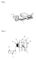
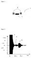
- Fig. 1 shows an example of the medical ultrasound device for embodying the present invention.
- the medical ultrasound device shown in Fig. 1 comprises a controller 25 for carrying out sending control of the ultrasound and analysis of a received signal and a transducer 4 connected through a cable 7.
- the transducer 4 is used for sending and receiving of an ultrasound.
- the transducer 4 may be constituted by a plurality of transducers conducting sending and receiving separately. If constituted by a plurality of transducers, the receiving side may be a sensor that can receive an ultrasound such as a microphone (hydrophone), pressure sensor or the like with high sensitivity instead of transducer. All the examples below describe a device constituted by a single transducer, but the present invention is not limited by those examples.
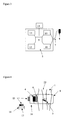
- FIG. 2 An example of an ultrasound fracture treatment device of the present invention is shown in Fig. 2 .
- an installation position of a transducer is determined by X-ray diagnostic imaging and the like so that an ultrasound for treatment hits a fracture site 3 of a femur 23.
- the transducer 4 is attached by transducer fixing means 8 at a prescribed position.
- an ultrasound gel 6 is applied as an ultrasound propagation substance between the transducer 4 and a soft tissue 1.
- An ultrasound signal for examination from the fracture treatment device 5 is transmitted to the transducer 4 through a cable 7 so as to irradiate ultrasound which frequency can be set at 1 to 5 MHz or preferably 1.5 MHz; burst width can be set at 5 to 200 ⁇ s or preferably 5 to 70 ⁇ s, or more preferably 20 ⁇ s; repetition cycle can be set at 10 Hz to 10 kHz or preferably 1 kHz; time average and spatial average of ultrasound output can be set at 0.75 to 30 mW/cm 2 or preferably 3 mW/cm 2 .
- An irradiation time can be easily adjusted by control means and the irradiation time may be changed according to a purpose, but irradiation continues for 1 to 10 seconds, for example. The longer the irradiation time, the better the accuracy becomes, therefore the irradiation time is set at approximately 10 seconds, for example at setting of prescription, or 1 to 5 seconds, for example, or preferably approximately 2 seconds at home, considering convenience.
- the ultrasound wave is reflected at a boundary where the acoustic impedance is different.
- the transducer 4 receives the ultrasound reflected at each boundary, and at this time, the transducer generates electric signal.
- the generated signal is sent to the fracture treatment device 5 through the cable 7, the signal is analyzed, and its result is displayed on display means (display portion) 14. If a medical staff determines that it is an appropriate result, this is recorded in recording means (memory) 12 and handled as a reference signal.
- recording means (memory) 12 recorded in recording means (memory) 12 and handled as a reference signal.
- a patient conducts treatment using the device in which the signal is recorded.
- Upon reception of the signal there is a possibility that a noise signal might be received due to external factors such as body movement, electric field, magnetic field and the like.
- the accuracy of the reflected signal from the target can be improved by sending a signal having a constant pulse width or duration, a pulse width of 20 ⁇ s, for example, and removing influence of noise.
- Non-destructive inspection used in the industrial field is distinguished from the present invention as the ultrasound image diagnosis.
- the non-destructive inspection similarly to the ultrasound image diagnosis, real-time imaging is carried out by a reflected signal obtained by the transducer. Based on the image, diagnosis of disease or flaws is made by trained professionals.
- diagnosis of disease or flaws is made by trained professionals.
- the present invention by making comparison with a recorded signal, an irradiated portion is determined. By this arrangement, reproducible positioning can be realized regardless of expertise of a user.
- the ultrasound fracture treatment device is used as an example, but the present invention is an art that can be applied to medical equipment requiring prescription of an appropriate position among medical equipment used for examination or treatment and can be realized noninvasively, that is, safely using a low-intensity ultrasound pulse.
- the transducer 4 when a patient conducts treatment at home, the transducer 4 is mounted at an attachment position prescribed by a medical institution, an ultrasound for examination is irradiated, and a detected signal can be compared with a reference signal determined by the medical institution. As shown in Fig. 5 , the signal comparison is made automatically by control means 9 provided with comparing means (comparison operation element) using intensity of received signal 18, time width of received signal 19, and delay time of received signal 20.
- a signal attenuation rate, transmission speed, and signal duration from the intensity of received signal 18 and the time width of received signal 19 of the reflected signal at the irradiation region, thickness of tissue such as fat, fascia, muscle, bone and the like is determined, respectively, and moreover by acquiring the signal attenuation rate and time to detection from the intensity of received signal 18 and the delay time of received signal 20, the distances between each tissue and the irradiation position and relative positions are determined and recorded.
- FIG. 5 shows a schematic waveform of a reflected signal when an ultrasound wave for examination with 1.5 MHz, burst width of 20 ⁇ s, repetition cycle of 1 kHz, and spatial average and time average of an ultrasound output of 3 mW/cm 2 is irradiated to a femur.
- the first signal with the shortest interval between ultrasound irradiation and signal receiving is expected to be reflected at the boundary between fat and muscle
- the second signal is expected to be reflected at the boundary between two types of muscle (fascia)
- a third signal with the longest delay time to receiving is reflected at the boundary between muscle and bone.
- the signal intensity is determined by a difference in acoustic impedance at the reflection boundary and attenuation relating to a distance over which the ultrasound wave is propagated.
- a signal reflected from the boundary between fat and muscle with a small difference in the acoustic impedance is smaller and the signal reflected from the boundary between muscle and bone with the acoustic impedance different by twice or more is larger.
- a reflected signal from a shallow boundary face has small influence of attenuation, while the influence of attenuation is larger on the reflected signal from a deep boundary face in a body.
- a region irradiating the ultrasound wave is known to be a layer of fat, muscle, another muscle, and bone.
- a time width of received signal for carrying out identification of continuity of signals, integration of signals exceeding a threshold value or analysis of an average value of signal intensity, for example, an accidental noise can be removed.
- material with different acoustic impedance is present nearby, reflected signals from a plurality of substances are synthesized and received, but it is possible to dissolve the synthesized signal using the time width of received signal and the acoustic impedance characteristics at the respective tissues and to make detection as the respective reflected signals.
- Fig. 12 shows an example of the waveform of transmitted received signal.
- Fig. 12 shows the transmitted signal 27 and the received signal 28 when the ultrasound for examination with 1.5 MHz, burst width of 20 ⁇ s, repetition cycle of 1 kHz, and spatial average and time average of the ultrasound output of 3 mW/cm 2 is irradiated to a femur.
- the received signal 28 is determined as reflection by fascia and another received signal 29 as reflection by bone.
- the irradiation position is judged to be a right position prescribed by the medical institution. If a position or angle of the transducer is different from pre-determined ones, there is a possibility of increase, decrease or loss of signal intensity, delay in a detection time or the like in Fig. 5 , for example. At this time, a degree of differences between calculated values and stored values, which determines if displacement occurs, can be preset for each patient appropriately, but ⁇ 10% for signal intensity and ⁇ 5% for arrival time can be specified as an error range, for example.
- the reflected wave signal has displacement from the reference signal apart from the preset error range, the fact that the treatment position is different from a position of initial setting is notified to the patient by the display means (display portion) 14. If it is within the error range of the reference signal, the ultrasound for examination is changed to an ultrasound for treatment, and the ultrasound with a frequency of 1.5 MHz, burst width of 200 ⁇ s, repetition cycle of 1 kHz, and spatial average and time average of the ultrasound output of 30 mW/cm 2 is irradiated from the transducer so as to start treatment.
- An optimal ultrasound wave irradiation can be continued by regularly checking and re-setting by the patient of the irradiation position at the medical institution.
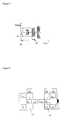
- Figure 3 shows the block diagram of the fracture treatment device.
- nature of the ultrasound irradiated by the transducer 4 is determined by a signal transmitted from the oscillating circuit 10 through the cable 7.
- An electric signal generated when the transducer 4 receives ultrasound is detected by the receiving circuit 11 through the cable 7 and stored in the recording means (memory) 12.
- Power supply means 13 is built-in power supply or means that can receive external power supply and is a driving source of the ultrasound fracture treatment device.
- the display means (display portion) 14 is means for providing information such as state of the fracture treatment device 5, irradiation situation of the ultrasound and the like.
- the above components are adjusted by the control means 9, and the control means 9 is also provided with a function as comparing means (comparison operation element) of the signal.
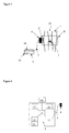
- Fig. 4 shows an application example of a wireless-type ultrasound fracture treatment device using femur fracture treatment as an example.
- the ultrasound signal at the treatment is transmitted to the transducer 4 through wireless communicating means 15.
- the signal received by the transducer 4 is sent to the wireless ultrasound irradiation device 16, the signal is sent to a wireless fracture treatment device 17 using the wireless communicating means 15, and the result can be displayed by the display means (display portion) 14.
- the irradiation position can be adjusted by position adjusting means (position adjustment mechanism).
- the irradiation position adjustment can be carried out manually or automatically.
- the automatic adjustment is conducted by irradiation-position automatic adjusting means 22, and the irradiation-position automatic adjusting means 22 is controlled by the control means 9.
- the irradiation-position automatic adjusting means 22, for example can be realized by using a conductive polymer material 26 as fixing means 8, which expands or contracts by applying voltage. A specific example is shown in Fig. 11 . This is an example in which a belt is used as the fixing means 8, and an ultrasound can be irradiated to a lower direction in Fig. 11 .
- an installation position of the transducer 4 on a body surface can be adjusted by expansion / contraction of the conductive polymer material 26.
- expansion / contraction in an arrow direction in Fig. 11 is possible.
- a distance that can be adjusted by this expansion / contraction depends on the type or size of the conductive polymer material, but expansion / contraction by approximately 1 mm to 5 cm is sufficient.
- a force to press the transducer 4 onto the body surface can be also adjusted.
- finer adjustment and optimization of the ultrasound irradiation position can be realized.
- the plurality of expansion / contraction spots can be expanded / contracted at the same time or independently.
- An example of expanding / contracting conductive polymer material 26 may include polypyrrole.
- Fig. 6 shows the configuration of the wireless fracture treatment device.
- the nature of the ultrasound irradiated by the transducer 4 is determined by a sending circuit in the wireless ultrasound irradiation device 16. An electric signal generated when the transducer 4 senses the ultrasound is detected by the receiving circuit 11.
- the wireless communicating means 15 is placed in the wireless ultrasound irradiation device 16 and the wireless fracture treatment device 17 and enables to transmit and receive the signal.
- the signal detected by the receiving circuit is sent to the recording means (memory) 12 in the wireless fracture treatment device 17 through the wireless communicating means 15 and stored therein.
- the power supply means 13 is built-in power supply or means that can be provided from external power supply and is a driving source of the wireless ultrasound irradiation device and the wireless fracture treatment device, respectively.
- the display means (display portion) 14 provides information such as states of the wireless ultrasound irradiation device 16 and the wireless fracture treatment device 17, communication state, irradiation state of the ultrasound wave and the like.
- the position of the transducer 4 can be automatically adjusted by the irradiation-position automatic adjusting means 22.
- the above elements are controlled by the control means 9.
- Fig. 7 shows an example of an ultrasound fracture treatment device with recording media applied to femur fracture treatment as an example.
- the signal received when prescription is set at start of treatment can be stored in a recording media 21.
- a patient can bring back only the recording media 21 for treatment at home and set it at the fracture treatment device owned by the patient at treatment.
- the recording media 21 in which a reference signal is stored is set at the fracture treatment device, an ultrasound wave for examination is irradiated at an attachment position prescribed by the medical institution, and comparison is made between a signal detected similarly as shown in the example in Fig. 2 and the reference signal determined by the medical institution.
- the patient can continue optimal ultrasound-wave irradiation.
- simpler treatment control is enabled.
- Fig. 8 shows an example of device configuration.
- the nature of the ultrasound irradiated by the transducer 4 is determined by a signal transmitted from the oscillating circuit 10 through the cable 7.
- the electric signal generated when the transducer 4 senses the ultrasound is detected by the receiving circuit 11 through the cable 7 and stored in the recording media 21 at the recording means (memory) 12.
- the power supply means 13 is built-in power supply or means that can be provided from external power supply and is a driving source for the ultrasound fracture treatment device.
- the display means (display portion) 14 is means for providing information such as a state of the fracture treatment device 5, irradiation state of the ultrasound and the like. The above elements are adjusted by the control means 9.
- Fig. 9 shows an example of device components.
- the nature of the irradiated ultrasound wave is determined by a signal from the oscillating circuit 10 to the transducer 4 integrated with the fracture treatment device 5.
- the electric signal generated when the transducer 4 senses the ultrasound is detected by the receiving circuit 11 and stored in the recording means (memory) 12.
- the power supply means 13 is built-in power supply or means that can be provided by from external power supply and is a driving source for the ultrasound fracture treatment device.
- the display means (display portion) 14 is means for providing information such as a state of the fracture treatment device 5, irradiation state of the ultrasound and the like.
- the above elements are adjusted by the control means 9, and the control means 9 is also provided with a function as the comparing means (comparison operation element) of the signal.
- Fig. 10 shows an example of an integral ultrasound fracture treatment device applied to femur fracture treatment.
- Fig. 10 cable 7 is eliminated and the ultrasound fracture treatment device 5 and the transducer 4 are integrated. Since the ultrasound fracture treatment device 5 itself can be used by fixing it on a body, the treatment device can be used regardless of the installation location.
- the medical ultrasound device of the present invention can be used for medical applications not limited to fracture treatment.
- it can be used for examination or treatment of muscle, fat, organ and the like at a specific position, not limited to the bone.
- it can be used in combination with other medical examination equipment or treatment equipment, and examination or treatment with high reproducibility for an intended position can be provided.
- a laser treatment device after checking a position by the medical ultrasound device of the present invention, a laser beam with property of traveling in straight lines can be irradiated to an intended portion efficiently.
- an intended portion can also be positioned with high reproducibility by the medical ultrasound device of the present invention.
- the medical ultrasound device of the present invention enables position adjustment with high reproducibility when medical equipment requiring positioning is to be used.
- the medical ultrasound device of the present invention By using the medical ultrasound device of the present invention, a position such as irradiation to the target position and the like can be confirmed with high reproducibility. As a result, examination or treatment is expected to be carried out accurately and efficiently. Further, by notifying a patient that examination or treatment is being carried out at an appropriate position, improvement effect of treatment compliance can be expected.
Landscapes
- Health & Medical Sciences (AREA)
- Life Sciences & Earth Sciences (AREA)
- Animal Behavior & Ethology (AREA)
- Veterinary Medicine (AREA)
- Public Health (AREA)
- Engineering & Computer Science (AREA)
- Biomedical Technology (AREA)
- General Health & Medical Sciences (AREA)
- Nuclear Medicine, Radiotherapy & Molecular Imaging (AREA)
- Radiology & Medical Imaging (AREA)
- Heart & Thoracic Surgery (AREA)
- Pathology (AREA)
- Surgery (AREA)
- Molecular Biology (AREA)
- Medical Informatics (AREA)
- Physics & Mathematics (AREA)
- Biophysics (AREA)
- Vascular Medicine (AREA)
- Surgical Instruments (AREA)
- Ultra Sonic Daignosis Equipment (AREA)
- Orthopedics, Nursing, And Contraception (AREA)
Applications Claiming Priority (2)
| Application Number | Priority Date | Filing Date | Title |
|---|---|---|---|
| JP2005360501 | 2005-12-14 | ||
| PCT/JP2006/325316 WO2007069775A1 (ja) | 2005-12-14 | 2006-12-13 | 照射位置確認機能を有する医療用超音波装置 |
Publications (2)
| Publication Number | Publication Date |
|---|---|
| EP1964518A1 true EP1964518A1 (de) | 2008-09-03 |
| EP1964518A4 EP1964518A4 (de) | 2010-05-26 |
Family
ID=38163076
Family Applications (1)
| Application Number | Title | Priority Date | Filing Date |
|---|---|---|---|
| EP06834986A Ceased EP1964518A4 (de) | 2005-12-14 | 2006-12-13 | Medizinisches ultraschallgerät mit bestrahlungspositions-bestätigender funktion |
Country Status (9)
| Country | Link |
|---|---|
| US (1) | US20100168574A1 (de) |
| EP (1) | EP1964518A4 (de) |
| JP (1) | JP4944795B2 (de) |
| KR (1) | KR101336575B1 (de) |
| CN (1) | CN101330876B (de) |
| AU (1) | AU2006325905B9 (de) |
| CA (1) | CA2633031A1 (de) |
| TW (1) | TWI433665B (de) |
| WO (1) | WO2007069775A1 (de) |
Cited By (2)
| Publication number | Priority date | Publication date | Assignee | Title |
|---|---|---|---|---|
| CN102469990A (zh) * | 2009-08-05 | 2012-05-23 | 帝人制药株式会社 | 具有照射位置确认功能的超声波检测装置及其方法 |
| US20130150756A1 (en) * | 2011-12-12 | 2013-06-13 | Shuki Vitek | Rib identification for transcostal focused ultrasound surgery |
Families Citing this family (7)
| Publication number | Priority date | Publication date | Assignee | Title |
|---|---|---|---|---|
| US8679019B2 (en) * | 2007-12-03 | 2014-03-25 | Bone Index Finland Oy | Method for measuring of thicknesses of materials using an ultrasound technique |
| FR2949965B1 (fr) * | 2009-09-17 | 2012-09-28 | Echosens | Procede pour la mesure d'au moins une propriete de tissu biologique |
| JP5438066B2 (ja) * | 2011-05-25 | 2014-03-12 | 日立アロカメディカル株式会社 | 超音波画像処理装置およびプログラム |
| US9788851B2 (en) * | 2012-04-18 | 2017-10-17 | Ethicon Llc | Surgical instrument with tissue density sensing |
| JP6297781B2 (ja) * | 2013-02-22 | 2018-03-20 | フクダ電子株式会社 | 超音波骨折治療器およびその制御方法 |
| JP6192001B2 (ja) * | 2013-02-22 | 2017-09-06 | フクダ電子株式会社 | 超音波骨折治療器 |
| KR101583302B1 (ko) | 2014-04-18 | 2016-01-07 | 부경대학교 산학협력단 | 진단 치료 겸용 광융합형 초음파기기 |
Family Cites Families (20)
| Publication number | Priority date | Publication date | Assignee | Title |
|---|---|---|---|---|
| US5054490A (en) * | 1988-05-11 | 1991-10-08 | Lunar Corporation | Ultrasonic densitometer device and method |
| US4930511A (en) * | 1988-05-11 | 1990-06-05 | Lunar Radiation, Inc. | Ultrasonic densitometer device and method |
| US5343863A (en) * | 1988-05-11 | 1994-09-06 | Lunar Corporation | Ultrasonic densitometer device and method |
| US4926870A (en) * | 1988-08-30 | 1990-05-22 | Osteo-Technology, Inc. | Method and apparatus for ultrasonic analysis of bone strength in vivo |
| FR2660186A1 (fr) * | 1990-03-27 | 1991-10-04 | Technomed Int Sa | Utilisation d'ultrasons pour la detection et la localisation d'une zone osseuse, procede et dispositif de detection et de localisation d'une telle zone osseuse par ultrasons. |
| FR2720260B1 (fr) * | 1994-05-30 | 1996-09-27 | Technomed Medical Systems | Utilisation d'un échographe en mode A pour la surveillance de la position d'un patient pendant une séance de thérapie, et procédé et appareil en comportant application. |
| US5547459A (en) * | 1994-10-25 | 1996-08-20 | Orthologic Corporation | Ultrasonic bone-therapy apparatus and method |
| US5556372A (en) * | 1995-02-15 | 1996-09-17 | Exogen, Inc. | Apparatus for ultrasonic bone treatment |
| US6004272A (en) * | 1995-06-07 | 1999-12-21 | Hologic, Inc. | Ultrasonic bone testing apparatus with repeatable positioning and repeatable coupling |
| JP3390607B2 (ja) * | 1996-08-05 | 2003-03-24 | 古野電気株式会社 | 超音波診断装置 |
| US5997490A (en) * | 1997-02-12 | 1999-12-07 | Exogen, Inc. | Method and system for therapeutically treating bone fractures and osteoporosis |
| US5906578A (en) * | 1997-06-18 | 1999-05-25 | Rajan; Govinda N. | Method and system for probe positioning in transesophageal echocardiography |
| DE19741586C1 (de) * | 1997-09-20 | 1999-07-29 | Theysohn Friedrich Fa | Ultraschallmeßgerät mit Sender und Empfänger für die Ortung der geometrischen Lage der Grenze zwischen einem ersten und einem zweiten Stoff von einem Bezugsort |
| JP2000300557A (ja) * | 1999-04-22 | 2000-10-31 | Aloka Co Ltd | 超音波診断装置 |
| JP2000325383A (ja) | 1999-05-20 | 2000-11-28 | Hitachi Ltd | 骨の治療・治癒診断方法及び治療・治癒診断装置 |
| JP2001231788A (ja) * | 2000-02-22 | 2001-08-28 | Hitachi Ltd | 骨の治療・治癒診断方法及び治療・治癒診断装置 |
| JP3609688B2 (ja) * | 2000-05-01 | 2005-01-12 | アロカ株式会社 | 超音波診断装置 |
| EP1345527A4 (de) * | 2000-11-28 | 2007-09-19 | Allez Physionix Ltd | Systeme und methoden zur durchführung nichtinvasiver physiologischer untersuchungen |
| WO2004075987A1 (en) * | 2003-02-28 | 2004-09-10 | Koninklijke Philips Electronics, N.V. | Motion-tracking improvements for hifu ultrasound therapy |
| US8016859B2 (en) * | 2006-02-17 | 2011-09-13 | Medtronic, Inc. | Dynamic treatment system and method of use |
-
2006
- 2006-12-13 CN CN2006800468369A patent/CN101330876B/zh not_active Expired - Fee Related
- 2006-12-13 WO PCT/JP2006/325316 patent/WO2007069775A1/ja not_active Ceased
- 2006-12-13 CA CA002633031A patent/CA2633031A1/en not_active Abandoned
- 2006-12-13 JP JP2007550266A patent/JP4944795B2/ja not_active Expired - Fee Related
- 2006-12-13 KR KR1020087016889A patent/KR101336575B1/ko not_active Expired - Fee Related
- 2006-12-13 AU AU2006325905A patent/AU2006325905B9/en not_active Ceased
- 2006-12-13 US US12/086,521 patent/US20100168574A1/en not_active Abandoned
- 2006-12-13 EP EP06834986A patent/EP1964518A4/de not_active Ceased
- 2006-12-14 TW TW095146919A patent/TWI433665B/zh active
Cited By (6)
| Publication number | Priority date | Publication date | Assignee | Title |
|---|---|---|---|---|
| CN102469990A (zh) * | 2009-08-05 | 2012-05-23 | 帝人制药株式会社 | 具有照射位置确认功能的超声波检测装置及其方法 |
| US20120130240A1 (en) * | 2009-08-05 | 2012-05-24 | Teijin Pharma Limited | Ultrasound detecting device having function of confirming irradiation position, and method thereof |
| EP2462873A4 (de) * | 2009-08-05 | 2013-01-30 | Teijin Pharma Ltd | Ultraschall-erkennungsvorrichtung mit funktion zur bestimmung der anwendungsposition und verfahren dafür |
| US9301729B2 (en) | 2009-08-05 | 2016-04-05 | Teijin Pharma Limited | Ultrasound detecting device having function of confirming irradiation position, and method thereof |
| US20130150756A1 (en) * | 2011-12-12 | 2013-06-13 | Shuki Vitek | Rib identification for transcostal focused ultrasound surgery |
| US10449395B2 (en) * | 2011-12-12 | 2019-10-22 | Insightec, Ltd. | Rib identification for transcostal focused ultrasound surgery |
Also Published As
| Publication number | Publication date |
|---|---|
| TW200730139A (en) | 2007-08-16 |
| AU2006325905B9 (en) | 2012-03-08 |
| EP1964518A4 (de) | 2010-05-26 |
| WO2007069775A1 (ja) | 2007-06-21 |
| KR101336575B1 (ko) | 2013-12-05 |
| JPWO2007069775A1 (ja) | 2009-05-28 |
| HK1125281A1 (en) | 2009-08-07 |
| CN101330876A (zh) | 2008-12-24 |
| AU2006325905A1 (en) | 2007-06-21 |
| JP4944795B2 (ja) | 2012-06-06 |
| TWI433665B (zh) | 2014-04-11 |
| KR20080078059A (ko) | 2008-08-26 |
| US20100168574A1 (en) | 2010-07-01 |
| AU2006325905B2 (en) | 2012-02-02 |
| CA2633031A1 (en) | 2007-06-21 |
| CN101330876B (zh) | 2012-11-07 |
Similar Documents
| Publication | Publication Date | Title |
|---|---|---|
| EP1615696B1 (de) | Therapeutischer schermodus-ultraschall | |
| US20210097702A1 (en) | Systems and methods for registering images obtained using various imaging modalities and verifying image registration | |
| JP4618810B2 (ja) | 剪断モード診断用超音波 | |
| JP5429822B2 (ja) | 神経などの構造の位置を特定するための非侵襲的装置 | |
| CN102469990B (zh) | 具有照射位置确认功能的超声波检测装置及其方法 | |
| CN1809399B (zh) | 剪切式治疗超声波 | |
| KR101389243B1 (ko) | 비침습적 초음파 방광내압 측정시스템 및 그 방법 | |
| AU2006325905B2 (en) | Medical ultrasonic apparatus having irradiation position-confirming function | |
| JP6952311B2 (ja) | 患部加熱システム、及び、腫瘍診断システム | |
| JPWO2008018612A1 (ja) | 超音波骨折治療器、骨折治療用受信装置及び骨折位置検査器 | |
| JP2001231788A (ja) | 骨の治療・治癒診断方法及び治療・治癒診断装置 | |
| JP2001299772A (ja) | 超音波治療装置 | |
| JP2014151123A (ja) | 超音波骨折治療装置 | |
| HK1123476A (en) | Medical ultrasonic apparatus having irradiation position-confirming function | |
| JP2009183454A (ja) | 周波数減衰特性を利用した超音波検査装置又は超音波照射位置検査方法 | |
| JP4567649B2 (ja) | トランスデューサ角度調節機構を有する超音波骨折治療器 | |
| HK1125281B (en) | Medical ultrasonic apparatus having irradiation position-confirming function | |
| JP2009183453A (ja) | 超音波伝搬速度を利用した超音波検査装置又は超音波照射位置検査方法 | |
| HK1086467B (en) | Shear mode diagnostic ultrasound |
Legal Events
| Date | Code | Title | Description |
|---|---|---|---|
| PUAI | Public reference made under article 153(3) epc to a published international application that has entered the european phase |
Free format text: ORIGINAL CODE: 0009012 |
|
| 17P | Request for examination filed |
Effective date: 20080703 |
|
| AK | Designated contracting states |
Kind code of ref document: A1 Designated state(s): AT BE BG CH CY CZ DE DK EE ES FI FR GB GR HU IE IS IT LI LT LU LV MC NL PL PT RO SE SI SK TR |
|
| REG | Reference to a national code |
Ref country code: HK Ref legal event code: DE Ref document number: 1123476 Country of ref document: HK |
|
| A4 | Supplementary search report drawn up and despatched |
Effective date: 20100423 |
|
| 17Q | First examination report despatched |
Effective date: 20100602 |
|
| DAX | Request for extension of the european patent (deleted) | ||
| REG | Reference to a national code |
Ref country code: HK Ref legal event code: WD Ref document number: 1123476 Country of ref document: HK |
|
| REG | Reference to a national code |
Ref country code: DE Ref legal event code: R003 |
|
| STAA | Information on the status of an ep patent application or granted ep patent |
Free format text: STATUS: THE APPLICATION HAS BEEN REFUSED |
|
| 18R | Application refused |
Effective date: 20181115 |