EP1964585A2 - Autonomes Gerät und Infusion - Google Patents
Autonomes Gerät und Infusion Download PDFInfo
- Publication number
- EP1964585A2 EP1964585A2 EP08447015A EP08447015A EP1964585A2 EP 1964585 A2 EP1964585 A2 EP 1964585A2 EP 08447015 A EP08447015 A EP 08447015A EP 08447015 A EP08447015 A EP 08447015A EP 1964585 A2 EP1964585 A2 EP 1964585A2
- Authority
- EP
- European Patent Office
- Prior art keywords
- pressure
- movable plate
- infusion
- spring
- plate
- Prior art date
- Legal status (The legal status is an assumption and is not a legal conclusion. Google has not performed a legal analysis and makes no representation as to the accuracy of the status listed.)
- Withdrawn
Links
- 230000010412 perfusion Effects 0.000 title claims abstract description 31
- 238000001802 infusion Methods 0.000 claims abstract description 69
- 230000006835 compression Effects 0.000 claims abstract description 10
- 238000007906 compression Methods 0.000 claims abstract description 10
- 230000007246 mechanism Effects 0.000 claims description 31
- 230000007423 decrease Effects 0.000 claims description 14
- 238000006073 displacement reaction Methods 0.000 claims description 6
- 230000000694 effects Effects 0.000 claims description 4
- 239000012530 fluid Substances 0.000 claims description 4
- 238000012544 monitoring process Methods 0.000 claims description 4
- 230000003247 decreasing effect Effects 0.000 claims description 3
- 230000002567 autonomic effect Effects 0.000 claims 6
- 230000009467 reduction Effects 0.000 abstract description 4
- 230000001105 regulatory effect Effects 0.000 abstract 1
- 230000009471 action Effects 0.000 description 7
- 239000007788 liquid Substances 0.000 description 7
- 239000003978 infusion fluid Substances 0.000 description 5
- 230000005484 gravity Effects 0.000 description 4
- 238000000034 method Methods 0.000 description 3
- 239000013060 biological fluid Substances 0.000 description 2
- 239000003814 drug Substances 0.000 description 2
- 230000011664 signaling Effects 0.000 description 2
- 230000000007 visual effect Effects 0.000 description 2
- 241001080024 Telles Species 0.000 description 1
- 230000006978 adaptation Effects 0.000 description 1
- 238000013459 approach Methods 0.000 description 1
- 230000003416 augmentation Effects 0.000 description 1
- 230000033228 biological regulation Effects 0.000 description 1
- 239000008280 blood Substances 0.000 description 1
- 210000004369 blood Anatomy 0.000 description 1
- 230000007547 defect Effects 0.000 description 1
- 229940079593 drug Drugs 0.000 description 1
- 239000007924 injection Substances 0.000 description 1
- 238000002347 injection Methods 0.000 description 1
- 238000012986 modification Methods 0.000 description 1
- 230000004048 modification Effects 0.000 description 1
- 230000005693 optoelectronics Effects 0.000 description 1
- 230000008520 organization Effects 0.000 description 1
- 230000007425 progressive decline Effects 0.000 description 1
- 230000035939 shock Effects 0.000 description 1
- 238000013519 translation Methods 0.000 description 1
Images


Classifications
-
- A—HUMAN NECESSITIES
- A61—MEDICAL OR VETERINARY SCIENCE; HYGIENE
- A61M—DEVICES FOR INTRODUCING MEDIA INTO, OR ONTO, THE BODY; DEVICES FOR TRANSDUCING BODY MEDIA OR FOR TAKING MEDIA FROM THE BODY; DEVICES FOR PRODUCING OR ENDING SLEEP OR STUPOR
- A61M5/00—Devices for bringing media into the body in a subcutaneous, intra-vascular or intramuscular way; Accessories therefor, e.g. filling or cleaning devices, arm-rests
- A61M5/14—Infusion devices, e.g. infusing by gravity; Blood infusion; Accessories therefor
- A61M5/142—Pressure infusion, e.g. using pumps
- A61M5/145—Pressure infusion, e.g. using pumps using pressurised reservoirs, e.g. pressurised by means of pistons
- A61M5/148—Pressure infusion, e.g. using pumps using pressurised reservoirs, e.g. pressurised by means of pistons flexible, e.g. independent bags
Definitions
- the present invention relates to an autonomous infusion apparatus according to the preamble of claim 1.
- Perfusion is an intervention technique, well known in the medical field, for the slow and continuous injection of a liquid, such as a drug or a biological fluid into an organism.
- a liquid such as a drug or a biological fluid into an organism.
- Such an intervention is commonly practiced, especially in human medicine. It is actually intended to compensate for losses of biological fluid (s), for example blood, suffered by an organism as a result, inter alia, of a surgical operation, a road accident or any circumstance leading to such losses. This is particularly the case in situations of armed conflict. It is also common that the body receiving the infusion is in shock.
- the infusion consists of a flow of a suitable liquid, contained in a flexible bag, from this pocket to the receiving organism, via a defined circuit also called perfusion line.
- This flow must be done with a flow as constant as possible, adapted to the needs of the receiving organization.
- the liquid pocket is maintained at a certain height above, the body to be infused, so as to ensure a liquid flow by gravity.
- This method is quite easily applied in hospitals or the like, where the bag can be suspended at a constant height thanks to a bracket and accompany the patient in his possible movements. Outside, for example at the scene of a road accident or a natural disaster, maintaining the pocket at the desired height mobilizes a member of the intervention staff, who is therefore no longer available for care missions proper. In addition, it is hardly possible to ensure a constant flow of liquid under these conditions.
- this method does not always ensure a sufficiently constant flow, even if the pocket is maintained at a constant height, since the pressure of the liquid - and therefore its flow - decreases as and as the bag empties. Finally, there is a significant risk that the patient, by an uncontrolled gesture, tears the infusion line that connects to the hanging bag.
- a significant disadvantage of the known autonomous perfusion devices is that they do not always ensure flow of the infusion fluid with a constant flow rate throughout the infusion.
- the perfusion pressure is indeed produced by a plate moving in parallel translation under the action of an elastic mechanism, also called pantograph, formed by crossed levers and springs.
- the perfusion pressure gradually decreased during the operation, particularly at the end of the infusion, where this reduction is very important. This is mainly due to the non-linearity of the tangent of the angle ⁇ (alpha) of opening of the pantograph when the angle ⁇ increases, that is to say when the pantograph deploys to apply the perfusion pressure. .
- the angle ⁇ is the angle formed by the axis of a lever and the axis of an associated spring. This non-linearity is particularly marked when the angle ⁇ approaches its final value. This results in a gradual decrease in the flow of the liquid and often even a great difficulty to completely empty the infusion bag.
- the present invention aims to provide an autonomous perfusion apparatus, with which it is possible on the one hand to ensure a constant flow of the infusion fluid throughout the duration of an infusion and secondly to empty as completely as possible the infusion bag.
- an autonomous infusion apparatus which comprises a housing and means for pressurizing a pressure bag between a fixed plate and a movable plate essentially parallel to said fixed plate and driven perpendicular thereto by an elastic mechanism between an arming position and a rest position, is characterized in that it is provided with a pressure regulator exerted on the pocket by said movable plate, comprising a spring having an axis perpendicular to the movable plate and one end of which is coupled to the movable plate and the other end is indirectly connected to a fixed support via a bushing containing a piston, attached on the one hand to the lower end of the spring and delimiting on the other hand a pressure chamber formed in the sleeve, said pressure chamber being connected in closed circuit, by a pipe leading to an orifice, to a pressure source P D , which exerts on the plunges a pressure force that compensates for the decrease in spring force on the movable plate during the infusion, which therefore compensates for the decrease in pressure
- the elastic mechanism comprises at least one, preferably two sets of crossed levers, parallel in pairs, in which the levers of the same assembly are joined by springs and the two sets of levers are assembled by transverse axes.
- the elastic mechanism thus constitutes a pantograph, controlling the displacement of the movable plate between its cocking position and its rest position under the effect of the pulling of the springs, which causes a variation of the opening angle ⁇ of the pantograph .
- the arming position of the movable plate is the position in which it is located when the elastic mechanism has its minimum opening angle and the springs are stretched, so before to start the infusion.
- the rest position of the plate mobile is the position in which the elastic mechanism has its maximum opening angle and the springs are relaxed, for example when the bag is empty.
- the autonomous infusion device is intended to be placed in particular on the body of a patient. It is therefore appropriate that the device has dimensions compatible with those of the user.
- the housing of the apparatus is substantially parallelepipedal in shape and has a length of 150 to 300 mm, a width of 100 to 200 mm and a height of 40 to 80 mm. These dimensions allow the device to receive the most commonly used infusion bags.
- the autonomous infusion apparatus comprises a housing and means for pressurizing a pressure bag between a fixed plate and a movable plate substantially parallel to said fixed plate and driven perpendicularly thereto by an elastic mechanism between an arming position and a rest position, and is characterized in that it is provided with an external pressure source supplying, via a pressure regulator, a flexible jack pressing on the movable plate, these elements being configured and arranged to increase during the infusion the pressure exerted by the flexible jack on the bag via the movable plate, this increase in pressure opposing the reduction of the pressure applied to the movable plate by said elastic mechanism and therefore the decrease of the outlet pressure of the bag during the infusion.
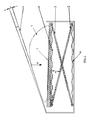
- figure 1 represents a first type of autonomous perfusion apparatus of the prior art, in which the present invention can be applied.
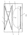
- the figure 2 represents a second type of autonomous infusion device of the prior art, in which the present invention can be applied.
- the figure 3 shows, for example, a flow control device installed according to the invention in the autonomous infusion device of the figure 1 .
- the figure 4 illustrates a variant of the flow regulator used according to the figure 3 .
- the figure 1 schematically illustrates a first type of autonomous infusion device forming part of the aforementioned state of the art.
- a housing it comprises a vertically movable lower plate 1, coupled to an elastic mechanism itself composed of crossed levers 2, 3.
- a top plate 4 forming a flip cover allows to exert on a pocket 5 a force F which, through the pocket 5, pushes the movable plate 1 down by arming the elastic mechanism 2, 3.
- the elastic mechanism 2, 3 is energized, or armed, by means of springs 6.
- the pocket 5 and compressed is ready for infusion.
- the figure 2 schematically illustrates a second type of autonomous infusion device also forming part of the state of the art mentioned above.
- This apparatus comprises, in a housing, a vertically movable top plate 1, coupled to an elastic mechanism itself composed of crossed levers 2, 3.
- the elastic mechanism 2, 3 is here placed above the movable plate 1, between the latter and a fixed upper wall 7 of the housing.
- An infusion bag 5, shown in phantom, may be deposited on a lower plate 8 fixed in the vertical direction but sliding horizontally in the manner of a drawer 4.
- An infusion pressure is produced by applying a force F by means of the movable plate 1, which is moved vertically downwards.
- the mechanism elastic 2, 3 is also driven by springs 6 to move the movable plate 1.
- FIG. 3 We have shown in the figure 3 an autonomous infusion apparatus, known per se, equipped, according to a first embodiment of the invention, with a flow regulator based on a helical compression spring 15 coupled to the movable plate 1.
- This movable plate 1 is represented here d one part in the high position, or rest position, in solid lines, and secondly in the low position, or arming position, in broken lines.
- the high position corresponds to the deployed state of the elastic mechanism 2, 3, that is to say at the end of the infusion.
- the angle ⁇ f is preferably 28 to 35 °.
- the low position corresponds to the folded state of the elastic mechanism 2, 3, that is to say at the beginning of the infusion (armed system).
- the angle ⁇ i is preferably 8 to 15 °.
- the upper face of the movable plate 1 has an inclination, in the direction of emptying the pocket, with an inclination angle ⁇ less than 10 ° relative to the horizontal.
- Such inclination can further improve the emptying rate of the pocket, which can thus reach 99%, by the action of gravity and the tangential force defined above.
- the coil spring 15 has its axis perpendicular to the movable plate.
- One end of the spring 15 is coupled to the movable plate 1 and the other end is connected indirectly to a fixed support 14 on the housing via a sleeve in which slides a piston 16, attached on the one hand to the lower end of the spring 15 and on the other hand delimiting a pressure chamber 17 formed in the sleeve.
- Said pressure chamber 17 is connected in a closed circuit, via a pipe 21 leading to an orifice 19, to a constant pressure source 20 (P D ), for example a mini-compressor, which exerts on the piston 16 a pressure force which compensates for the progressive decrease in the force of the spring 15 on the movable plate 1 during the infusion.
- P D constant pressure source 20
- the piston 16 is positioned at the bottom of the stop in the sleeve.
- the movable plate 1 rises, under the effect of the elastic mechanism 2,3.
- the compression spring 15 tends to relax, which gradually reduces the additional force applied to the movable plate 1 by the spring 15.
- FIG 4 there is shown a variant of the flow regulator 10 according to the invention.
- the regulator 10 is coupled to the movable upper plate 1, which moves towards a fixed lower plate 11 under the action of an elastic mechanism, known per se and not shown here (eg a pantograph).
- an elastic mechanism known per se and not shown here (eg a pantograph).
- the angle ⁇ defined above but not shown here would of course be provided on the fixed lower plate 11.
- the movable plate 1 thus moves downward towards a lower fixed plate 11.
- the invention is however not limited to this particular embodiment. On the contrary, it also applies, with a simple adaptation, to an apparatus in which the movable plate 1 moves upwards in the direction of an upper fixed plate.
- the regulator 10 comprises a substantially rectangular rigid frame composed of two rods 12 parallel to each other fixed perpendicularly to the movable plate 1 by a first end and connected to one another at their other end by a cross member 13 parallel to the movable plate 1.
- a fixed support 14 is provided in the housing, not shown, of the infusion apparatus, between the movable plate 1 and the crosspiece 13.
- a helical spring 15 is mounted between the crosspiece 13 and the fixed support 14, with its longitudinal axis parallel to the rods 12 and therefore perpendicular to the movable plate 1. At its upper end, the spring 15 bears in a conventional manner on the cross member 13. At its opposite end, the spring 15 is connected indirectly to the fixed support 14 by a socket, not marked, in which there is provided a piston 16, attached firstly to the lower end of the spring 15 and delimiting on the other hand a pressure chamber 17 formed in the sleeve.
- the pressure chamber 17 is connected, via a connector 19, firstly by a first pipe 21 at the outlet of a pressure source 20 (P D ), for example a mini-compressor, and secondly by a second conduit 22 to an inflatable balloon 23, acting as a flexible jack, in contact in the housing between the support plate 14 and the movable plate 1.
- P D pressure source 20
- the pressure P D supplied by the pressure source is injected through the connector 19 into the pressure chamber 17 and acts upwards on the piston 16; this pressure P D is always greater than the pressure P R exerted in the opposite direction by the spring 15. At the same time, the balloon 23 inflates.
- the pressure difference causes the piston 16 to move upwards, thus releasing calibrated orifices (not shown) in the regulator 10, by which a certain quantity of pressure fluid (for example compressed air) Q F escapes from the pressure chamber 17 to the outside environment.
- a certain quantity of pressure fluid for example compressed air
- Q F escapes from the pressure chamber 17 to the outside environment.
- the spring 15 is compressed more and more as a result of the displacement of the movable plate 1; the pressure P R increases, the piston 16 goes down to the pressure chamber 17 and gradually closes the exhaust ports, which causes a decrease in the leakage Q F and consequently an increase in the pressure P I and therefore the pressure in the balloon which, in the example, returns to 150 mbar.
- This increase in the pressure P I opposes the pressure decrease in the pocket 5 due to the non-linearity of the tangent ⁇ during the infusion.
- An autonomous perfusion device equipped with a flow regulator according to the invention thus makes it possible to achieve a constant pressure, and thus a flow rate, of 95 to 99%.
- the rate of emptying the pockets is improved to 99%, thanks to the angle slope ⁇ of 3 to 5 ° provided on the upper face of the lower plate.
- the device of the invention may also comprise modules known per se, which allow better control of the progress and monitoring of the infusion.
- a second module includes means for controlling the flow rate of the infusion liquid, in particular using a mass flow meter, with a display and alarm system in case of flow variation beyond predetermined limits.
- a third module can be dedicated to the control of infusion and the regulation of infusion fluid flow.
- This module includes for example a mass flow meter for controlling the flow rate, as well as a flow control system using a microvalve controlled by a servomotor and acting on the section of a compressible tube.
- This module advantageously comprises flow display means and an alarm system in case of variation of the flow rate beyond predetermined limits.
Landscapes
- Health & Medical Sciences (AREA)
- Vascular Medicine (AREA)
- Engineering & Computer Science (AREA)
- Anesthesiology (AREA)
- Biomedical Technology (AREA)
- Heart & Thoracic Surgery (AREA)
- Hematology (AREA)
- Life Sciences & Earth Sciences (AREA)
- Animal Behavior & Ethology (AREA)
- General Health & Medical Sciences (AREA)
- Public Health (AREA)
- Veterinary Medicine (AREA)
- Infusion, Injection, And Reservoir Apparatuses (AREA)
Applications Claiming Priority (1)
| Application Number | Priority Date | Filing Date | Title |
|---|---|---|---|
| BE2007/0091A BE1017480A3 (fr) | 2007-03-02 | 2007-03-02 | Appareil autonome de perfusion. |
Publications (2)
| Publication Number | Publication Date |
|---|---|
| EP1964585A2 true EP1964585A2 (de) | 2008-09-03 |
| EP1964585A3 EP1964585A3 (de) | 2008-12-31 |
Family
ID=38537574
Family Applications (1)
| Application Number | Title | Priority Date | Filing Date |
|---|---|---|---|
| EP08447015A Withdrawn EP1964585A3 (de) | 2007-03-02 | 2008-02-29 | Autonomes Gerät und Infusion |
Country Status (2)
| Country | Link |
|---|---|
| EP (1) | EP1964585A3 (de) |
| BE (1) | BE1017480A3 (de) |
Cited By (7)
| Publication number | Priority date | Publication date | Assignee | Title |
|---|---|---|---|---|
| WO2010003291A1 (zh) * | 2008-07-11 | 2010-01-14 | Lin Ronghua | 一种自动输液装置 |
| CN103405825A (zh) * | 2013-08-26 | 2013-11-27 | 苏州鼎诺医疗设备有限公司 | 输液泵 |
| WO2015022287A1 (fr) * | 2013-08-13 | 2015-02-19 | Mahusaca Sprl | Pompe a liquides autonome pour vehiculer un fluide vers un etre vivant |
| CN106139308A (zh) * | 2016-08-22 | 2016-11-23 | 中国人民解放军第三军医大学第三附属医院 | 伸缩式输液悬挂装置 |
| CN107096091A (zh) * | 2017-06-08 | 2017-08-29 | 广州欧浦瑞医疗科技有限公司 | 一种新型机械式输液加压装置及加压方法 |
| CN107569736A (zh) * | 2017-08-29 | 2018-01-12 | 江苏义倍医疗科技股份有限公司 | 一种便携式机械输液泵 |
| CN113406316A (zh) * | 2021-06-17 | 2021-09-17 | 重庆医科大学附属儿童医院 | 一种电生理膜片钳灌流装置 |
Families Citing this family (1)
| Publication number | Priority date | Publication date | Assignee | Title |
|---|---|---|---|---|
| CN119236227A (zh) * | 2024-11-26 | 2025-01-03 | 中国人民解放军总医院第三医学中心 | 一种便携式化疗药物精准输注装置 |
Citations (3)
| Publication number | Priority date | Publication date | Assignee | Title |
|---|---|---|---|---|
| US4157771A (en) | 1977-10-07 | 1979-06-12 | The Gorman-Rupp Company | Bag compressing device for dispensing fluid |
| FR2654230A1 (fr) | 1989-11-06 | 1991-05-10 | Cobe Lab | Appareil de regulation de debit de fluide, notamment du fluide administre a un patient. |
| WO1997034651A1 (en) | 1996-03-19 | 1997-09-25 | Mcphee Charles J | Platen pump |
Family Cites Families (2)
| Publication number | Priority date | Publication date | Assignee | Title |
|---|---|---|---|---|
| FR2677887A1 (fr) * | 1991-06-24 | 1992-12-24 | Adecef | Appareil autonome de perfusion. |
| BE1013694A3 (fr) * | 2000-09-21 | 2002-06-04 | Beria Sa | Dispositif autonome de perfusion. |
-
2007
- 2007-03-02 BE BE2007/0091A patent/BE1017480A3/fr not_active IP Right Cessation
-
2008
- 2008-02-29 EP EP08447015A patent/EP1964585A3/de not_active Withdrawn
Patent Citations (3)
| Publication number | Priority date | Publication date | Assignee | Title |
|---|---|---|---|---|
| US4157771A (en) | 1977-10-07 | 1979-06-12 | The Gorman-Rupp Company | Bag compressing device for dispensing fluid |
| FR2654230A1 (fr) | 1989-11-06 | 1991-05-10 | Cobe Lab | Appareil de regulation de debit de fluide, notamment du fluide administre a un patient. |
| WO1997034651A1 (en) | 1996-03-19 | 1997-09-25 | Mcphee Charles J | Platen pump |
Cited By (10)
| Publication number | Priority date | Publication date | Assignee | Title |
|---|---|---|---|---|
| WO2010003291A1 (zh) * | 2008-07-11 | 2010-01-14 | Lin Ronghua | 一种自动输液装置 |
| WO2015022287A1 (fr) * | 2013-08-13 | 2015-02-19 | Mahusaca Sprl | Pompe a liquides autonome pour vehiculer un fluide vers un etre vivant |
| BE1021887B1 (fr) * | 2013-08-13 | 2016-01-25 | Mahusaca Sprl | Appareil autonome pour vehiculer un fluide vers un etre vivant. |
| CN103405825A (zh) * | 2013-08-26 | 2013-11-27 | 苏州鼎诺医疗设备有限公司 | 输液泵 |
| CN103405825B (zh) * | 2013-08-26 | 2015-05-13 | 深圳圣诺医疗设备有限公司 | 输液泵 |
| CN106139308A (zh) * | 2016-08-22 | 2016-11-23 | 中国人民解放军第三军医大学第三附属医院 | 伸缩式输液悬挂装置 |
| CN107096091A (zh) * | 2017-06-08 | 2017-08-29 | 广州欧浦瑞医疗科技有限公司 | 一种新型机械式输液加压装置及加压方法 |
| CN107569736A (zh) * | 2017-08-29 | 2018-01-12 | 江苏义倍医疗科技股份有限公司 | 一种便携式机械输液泵 |
| CN113406316A (zh) * | 2021-06-17 | 2021-09-17 | 重庆医科大学附属儿童医院 | 一种电生理膜片钳灌流装置 |
| CN113406316B (zh) * | 2021-06-17 | 2023-08-08 | 重庆医科大学附属儿童医院 | 一种电生理膜片钳灌流装置 |
Also Published As
| Publication number | Publication date |
|---|---|
| BE1017480A3 (fr) | 2008-10-07 |
| EP1964585A3 (de) | 2008-12-31 |
Similar Documents
| Publication | Publication Date | Title |
|---|---|---|
| BE1017480A3 (fr) | Appareil autonome de perfusion. | |
| EP1653832B1 (de) | Vorrichtung für die zubereitung eines kaffeegetränks | |
| CH627351A5 (fr) | Dispositif dynamique de calage du pied et de la jambe dans un ensemble rigide. | |
| FR2641975A1 (fr) | Appareil respiratoire a fonctionnement en circulation avec surpression | |
| EP0013976B1 (de) | Verteilvorrichtung für tiefgefrorene Waren | |
| CA2053535C (fr) | Installation pour soutenir les lattes d'un sommier a lattes | |
| FR2666229A1 (fr) | Regulateur d'aspiration autoreglable. | |
| WO1998046136A1 (fr) | Seringue a compartiments multiples | |
| BE1013694A3 (fr) | Dispositif autonome de perfusion. | |
| FR2489469A1 (fr) | Appareil empechant l'ecoulement d'un fluide en sens contraire a la normale et comportant une soupape de surete, notamment pour l'alimentation en eau d'une grosse installation d'irrigation de cultures | |
| FR2740147A1 (fr) | Systeme pour la mise sous tension des fils de chaine sur un chassis d'ensouple | |
| FR2664485A1 (fr) | Procede et dispositif pour limiter une pression dans un brassard destine a etre utilise pour mesurer une pression arterielle. | |
| EP0077269A1 (de) | Hilfsvorrichtung zum Heben einer Person aus einer Badewanne | |
| BE1017668A3 (fr) | Systeme d'infiltration de liquide contenu dans une poche souple. | |
| FR2683320A1 (fr) | Capteur de pression intra-abdominale pour mannequin anthropomorphe. | |
| EP3033124B1 (de) | Selbständige flüssigkeitspumpe zur förderung einer flüssigkeit zu einem patienten | |
| FR2677887A1 (fr) | Appareil autonome de perfusion. | |
| CA2044576C (fr) | Tire-coussinets | |
| EP0800939A1 (de) | Vorrichtung zur Niveauregelung für Fahrzeuge mit Luftfederung | |
| FR2940622A1 (fr) | Equipement de frappe pour l'entrainement et la pratique de sports de combat | |
| FR2887458A1 (fr) | Dispositif de perfusion | |
| FR3068932B1 (fr) | Dispositif de suspension pour siege de vehicule comportant un support hydraulique associe a des verins. | |
| FR3155823A1 (fr) | Dispositif d’affalage hydraulique à commande manuelle pour engin de levage | |
| EP0372049A1 (de) | System für die infusion einer flüssigkeit in die menschliche blutbahn | |
| WO2008009819A2 (fr) | Dispositif d'assistance permettant a un utilisateur a mobilite reduite de s'asseoir et de se relever sur un element d'assise |
Legal Events
| Date | Code | Title | Description |
|---|---|---|---|
| PUAI | Public reference made under article 153(3) epc to a published international application that has entered the european phase |
Free format text: ORIGINAL CODE: 0009012 |
|
| AK | Designated contracting states |
Kind code of ref document: A2 Designated state(s): AT BE BG CH CY CZ DE DK EE ES FI FR GB GR HR HU IE IS IT LI LT LU LV MC MT NL NO PL PT RO SE SI SK TR |
|
| AX | Request for extension of the european patent |
Extension state: AL BA MK RS |
|
| PUAL | Search report despatched |
Free format text: ORIGINAL CODE: 0009013 |
|
| AK | Designated contracting states |
Kind code of ref document: A3 Designated state(s): AT BE BG CH CY CZ DE DK EE ES FI FR GB GR HR HU IE IS IT LI LT LU LV MC MT NL NO PL PT RO SE SI SK TR |
|
| AX | Request for extension of the european patent |
Extension state: AL BA MK RS |
|
| 17P | Request for examination filed |
Effective date: 20090409 |
|
| 17Q | First examination report despatched |
Effective date: 20090513 |
|
| AKX | Designation fees paid |
Designated state(s): AT BE BG CH CY CZ DE DK EE ES FI FR GB GR HR HU IE IS IT LI LT LU LV MC MT NL NO PL PT RO SE SI SK TR |
|
| GRAP | Despatch of communication of intention to grant a patent |
Free format text: ORIGINAL CODE: EPIDOSNIGR1 |
|
| RIN1 | Information on inventor provided before grant (corrected) |
Inventor name: RENARD, PHILIPPE Inventor name: PEETERS, THIERRY Inventor name: MAWET, PASCAL |
|
| RTI1 | Title (correction) |
Free format text: STANDALONE DEVICE OF PERFUSION |
|
| STAA | Information on the status of an ep patent application or granted ep patent |
Free format text: STATUS: THE APPLICATION IS DEEMED TO BE WITHDRAWN |
|
| 18D | Application deemed to be withdrawn |
Effective date: 20120831 |