EP1964783A2 - Maschine und Verfahren zur Anbringung von Etiketten an Paketen - Google Patents
Maschine und Verfahren zur Anbringung von Etiketten an Paketen Download PDFInfo
- Publication number
- EP1964783A2 EP1964783A2 EP08150391A EP08150391A EP1964783A2 EP 1964783 A2 EP1964783 A2 EP 1964783A2 EP 08150391 A EP08150391 A EP 08150391A EP 08150391 A EP08150391 A EP 08150391A EP 1964783 A2 EP1964783 A2 EP 1964783A2
- Authority
- EP
- European Patent Office
- Prior art keywords
- machine
- container
- applicator
- label
- application station
- Prior art date
- Legal status (The legal status is an assumption and is not a legal conclusion. Google has not performed a legal analysis and makes no representation as to the accuracy of the status listed.)
- Granted
Links
- 238000000034 method Methods 0.000 title claims description 10
- 239000000853 adhesive Substances 0.000 claims abstract description 24
- 230000001070 adhesive effect Effects 0.000 claims abstract description 24
- 230000005540 biological transmission Effects 0.000 claims description 11
- 238000005520 cutting process Methods 0.000 claims description 10
- 241000208125 Nicotiana Species 0.000 claims description 9
- 235000002637 Nicotiana tabacum Nutrition 0.000 claims description 9
- 238000011144 upstream manufacturing Methods 0.000 claims description 6
- 230000003213 activating effect Effects 0.000 claims description 3
- 239000002344 surface layer Substances 0.000 claims description 3
- 230000014759 maintenance of location Effects 0.000 claims description 2
- 230000005855 radiation Effects 0.000 claims description 2
- 235000019504 cigarettes Nutrition 0.000 abstract description 6
- 239000007921 spray Substances 0.000 description 7
- 230000000712 assembly Effects 0.000 description 4
- 238000000429 assembly Methods 0.000 description 4
- 238000004519 manufacturing process Methods 0.000 description 3
- 230000015572 biosynthetic process Effects 0.000 description 1
- 238000004140 cleaning Methods 0.000 description 1
- 239000000463 material Substances 0.000 description 1
- 238000005507 spraying Methods 0.000 description 1
Images




Classifications
-
- B—PERFORMING OPERATIONS; TRANSPORTING
- B65—CONVEYING; PACKING; STORING; HANDLING THIN OR FILAMENTARY MATERIAL
- B65C—LABELLING OR TAGGING MACHINES, APPARATUS, OR PROCESSES
- B65C1/00—Labelling flat essentially-rigid surfaces
- B65C1/02—Affixing labels to one flat surface of articles, e.g. of packages, of flat bands
- B65C1/021—Affixing labels to one flat surface of articles, e.g. of packages, of flat bands the label being applied by movement of the labelling head towards the article
- B65C1/023—Affixing labels to one flat surface of articles, e.g. of packages, of flat bands the label being applied by movement of the labelling head towards the article and being supplied from a stack
-
- B—PERFORMING OPERATIONS; TRANSPORTING
- B65—CONVEYING; PACKING; STORING; HANDLING THIN OR FILAMENTARY MATERIAL
- B65C—LABELLING OR TAGGING MACHINES, APPARATUS, OR PROCESSES
- B65C1/00—Labelling flat essentially-rigid surfaces
- B65C1/04—Affixing labels, e.g. wrap-around labels, to two or more flat surfaces of a polyhedral article
- B65C1/042—Affixing labels, e.g. wrap-around labels, to two or more flat surfaces of a polyhedral article using two or more applicators, e.g. cooperating rollers or brushes
-
- B—PERFORMING OPERATIONS; TRANSPORTING
- B65—CONVEYING; PACKING; STORING; HANDLING THIN OR FILAMENTARY MATERIAL
- B65C—LABELLING OR TAGGING MACHINES, APPARATUS, OR PROCESSES
- B65C9/00—Details of labelling machines or apparatus
- B65C9/08—Label feeding
- B65C9/12—Removing separate labels from stacks
- B65C9/14—Removing separate labels from stacks by vacuum
-
- B—PERFORMING OPERATIONS; TRANSPORTING
- B65—CONVEYING; PACKING; STORING; HANDLING THIN OR FILAMENTARY MATERIAL
- B65C—LABELLING OR TAGGING MACHINES, APPARATUS, OR PROCESSES
- B65C9/00—Details of labelling machines or apparatus
- B65C9/20—Gluing the labels or articles
- B65C9/22—Gluing the labels or articles by wetting, e.g. by applying liquid glue or a liquid to a dry glue coating
- B65C9/2204—Gluing the labels or articles by wetting, e.g. by applying liquid glue or a liquid to a dry glue coating using spraying means
- B65C9/2208—Applying the liquid on the article
-
- Y—GENERAL TAGGING OF NEW TECHNOLOGICAL DEVELOPMENTS; GENERAL TAGGING OF CROSS-SECTIONAL TECHNOLOGIES SPANNING OVER SEVERAL SECTIONS OF THE IPC; TECHNICAL SUBJECTS COVERED BY FORMER USPC CROSS-REFERENCE ART COLLECTIONS [XRACs] AND DIGESTS
- Y10—TECHNICAL SUBJECTS COVERED BY FORMER USPC
- Y10T—TECHNICAL SUBJECTS COVERED BY FORMER US CLASSIFICATION
- Y10T156/00—Adhesive bonding and miscellaneous chemical manufacture
- Y10T156/12—Surface bonding means and/or assembly means with cutting, punching, piercing, severing or tearing
-
- Y—GENERAL TAGGING OF NEW TECHNOLOGICAL DEVELOPMENTS; GENERAL TAGGING OF CROSS-SECTIONAL TECHNOLOGIES SPANNING OVER SEVERAL SECTIONS OF THE IPC; TECHNICAL SUBJECTS COVERED BY FORMER USPC CROSS-REFERENCE ART COLLECTIONS [XRACs] AND DIGESTS
- Y10—TECHNICAL SUBJECTS COVERED BY FORMER USPC
- Y10T—TECHNICAL SUBJECTS COVERED BY FORMER US CLASSIFICATION
- Y10T156/00—Adhesive bonding and miscellaneous chemical manufacture
- Y10T156/17—Surface bonding means and/or assemblymeans with work feeding or handling means
- Y10T156/1702—For plural parts or plural areas of single part
- Y10T156/1744—Means bringing discrete articles into assembled relationship
-
- Y—GENERAL TAGGING OF NEW TECHNOLOGICAL DEVELOPMENTS; GENERAL TAGGING OF CROSS-SECTIONAL TECHNOLOGIES SPANNING OVER SEVERAL SECTIONS OF THE IPC; TECHNICAL SUBJECTS COVERED BY FORMER USPC CROSS-REFERENCE ART COLLECTIONS [XRACs] AND DIGESTS
- Y10—TECHNICAL SUBJECTS COVERED BY FORMER USPC
- Y10T—TECHNICAL SUBJECTS COVERED BY FORMER US CLASSIFICATION
- Y10T156/00—Adhesive bonding and miscellaneous chemical manufacture
- Y10T156/17—Surface bonding means and/or assemblymeans with work feeding or handling means
- Y10T156/1702—For plural parts or plural areas of single part
- Y10T156/1744—Means bringing discrete articles into assembled relationship
- Y10T156/1768—Means simultaneously conveying plural articles from a single source and serially presenting them to an assembly station
-
- Y—GENERAL TAGGING OF NEW TECHNOLOGICAL DEVELOPMENTS; GENERAL TAGGING OF CROSS-SECTIONAL TECHNOLOGIES SPANNING OVER SEVERAL SECTIONS OF THE IPC; TECHNICAL SUBJECTS COVERED BY FORMER USPC CROSS-REFERENCE ART COLLECTIONS [XRACs] AND DIGESTS
- Y10—TECHNICAL SUBJECTS COVERED BY FORMER USPC
- Y10T—TECHNICAL SUBJECTS COVERED BY FORMER US CLASSIFICATION
- Y10T156/00—Adhesive bonding and miscellaneous chemical manufacture
- Y10T156/17—Surface bonding means and/or assemblymeans with work feeding or handling means
- Y10T156/1702—For plural parts or plural areas of single part
- Y10T156/1744—Means bringing discrete articles into assembled relationship
- Y10T156/1776—Means separating articles from bulk source
-
- Y—GENERAL TAGGING OF NEW TECHNOLOGICAL DEVELOPMENTS; GENERAL TAGGING OF CROSS-SECTIONAL TECHNOLOGIES SPANNING OVER SEVERAL SECTIONS OF THE IPC; TECHNICAL SUBJECTS COVERED BY FORMER USPC CROSS-REFERENCE ART COLLECTIONS [XRACs] AND DIGESTS
- Y10—TECHNICAL SUBJECTS COVERED BY FORMER USPC
- Y10T—TECHNICAL SUBJECTS COVERED BY FORMER US CLASSIFICATION
- Y10T156/00—Adhesive bonding and miscellaneous chemical manufacture
- Y10T156/17—Surface bonding means and/or assemblymeans with work feeding or handling means
- Y10T156/1702—For plural parts or plural areas of single part
- Y10T156/1744—Means bringing discrete articles into assembled relationship
- Y10T156/1776—Means separating articles from bulk source
- Y10T156/1778—Stacked sheet source
- Y10T156/178—Rotary or pivoted picker
Definitions
- the present invention relates to a machine and method for applying objects to containers in the tobacco industry.
- the present invention relates to a machine for applying objects, normally labels, to containers in the tobacco industry.
- the machine comprises a conveying device for feeding a container in a travelling direction along a given path through an application station; and a feed device for feeding one object at a time along a feed path from a transfer station to the application station, and which comprises at least one gripping assembly for retaining the object and applying the object to a given portion of the container.
- Known machines of the type described above often comprise a gumming device located along the feed path and having one or more spray nozzles for spraying the object with adhesive.
- Machine stoppages to carry out the above jobs inevitably reduce the overall output rate of the machines.
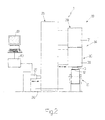
- Number 1 in Figure 1 indicates as a whole a machine for applying labels 2 (in particular, inland revenue stamps) to packets 3 of cigarettes (not shown).
- packet 3 is a rigid, hinged-lid type, and comprises a cup-shaped body 4 and a lid 5.
- packet 3 When lid 5 is closed, packet 3 comprises a front wall (not shown); a rear wall 6; a bottom wall (not shown); a top wall 7; and two lateral walls 8 (only one shown).
- Lid 5 and cup-shaped body 4 are connected by a hinge (shown by a dot-and-dash line) on rear wall 6, and are separated by a parting line 9 extending across the front wall (not shown) and lateral walls 8.
- packet 3 is shown as positioned on conveying device 10.
- Machine 1 ( Figures 1 and 2 ) comprises a conveying device 10 for feeding packets 3 horizontally in a travelling direction A along a given path P1 through an application station 11, where labels 2 are each applied to a given portion of a respective packet 3.
- Conveying device 10 ( Figure 9 ) comprises a belt 12, on which are formed a number of seats, each for housing a respective packet 3.
- Machine 1 also comprises a gumming device 13 located along given path P1, at a gumming station 14 upstream from application station 11, to apply adhesive to the given portion of each packet 3 to which respective label 2 is to be applied.
- a gumming device 13 located along given path P1, at a gumming station 14 upstream from application station 11, to apply adhesive to the given portion of each packet 3 to which respective label 2 is to be applied.
- Gumming device 13 comprises an applicator 15 in turn comprising two spray nozzles 16, which are oriented substantially vertically downwards, and each emit two jets of adhesive onto wall 6 of each packet 3.
- Gumming device 13 also comprises an applicator 17 in turn comprising two spray nozzles 18, which are oriented substantially horizontally, and each emit two jets of adhesive onto one of lateral walls 8 of each packet 3.
- Spray nozzles 16 are offset horizontally with respect to both the travelling direction A and a direction perpendicular to travelling direction A.
- Spray nozzles 18 are offset vertically, i.e. one of spray nozzles 18 is located higher than the other.
- applicator 15 and/or applicator 17 release/releases the adhesive in contact with packet 3; in which case, an actuating unit (not shown) is preferably provided at gumming station 14 to move packet 3, crosswise to travelling direction A, to and from a position contacting applicator 15 (and/or applicator 17). Alternatively, the actuating unit (not shown) moves applicator 15 (and/or applicator 17), crosswise to travelling direction A, to and from a position contacting packet 3.
- packet 3 and applicator 15 are moved with respect to each other, crosswise to travelling direction A, to bring packet 3 and applicator 15 (and/or applicator 17) into contact with each other; at which point, adhesive supply is activated and then cut off. Once the adhesive supply is cut off, packet 3 and applicator 15 (and/or applicator 17) are moved with respect to each other, crosswise to travelling direction A, to detach packet 3 and applicator 15 (and/or applicator 17).
- the above method provides for fast, effective cleaning of applicator 15 (and/or applicator 17), and so reducing the likelihood of adhesive strands forming and fouling the machine.
- Machine 1 also comprises a feed assembly 19 for feeding labels 2 to application station 11.
- Feed assembly 19 comprises a substantially horizontal hopper 20 containing a stack 21 of labels 2, and having an outlet 22 at a transfer station 23; and a feed device 24, which withdraws labels 2 one at a time from outlet 22, feeds labels 2 along a feed path P2, and applies each label 2 to a respective packet 3 at application station 11.
- machine 1 has no hopper 20, and labels 2 are cut off a strip at transfer station 23.
- feed assembly 19 comprises a frame 25, to which feed device 24, hopper 20, and gumming device 13 are fitted; guides 26 crosswise to direction A, and along which frame 25 runs in use; and a hydraulic actuator 27 for moving frame 25 crosswise, in particular, perpendicularly to direction A.
- Moving feed assembly 19 crosswise to direction A provides for rapidly and effectively adjusting the portion of each packet 3 to which respective label 2 is applied.
- Feed device 24 ( Figures 1 and 2 ) comprises a transfer unit 28 for conveying labels 2 successively and one at a time from transfer station 23 to a transfer station 29; and an application unit 30 for conveying labels 2 from transfer station 29 to application station 11, and applying labels 2 to packets 3.
- Transfer unit 28 comprises a wheel 31 having a number of - in the example shown, six - gripping assemblies 32 equally spaced along the periphery of wheel 31; and each gripping assembly 32 is mounted to oscillate about a respective axis 33, and has a suction head 34 for engaging a respective label 2 by suction at each operating cycle.
- gripping assemblies 32 oscillate about respective axes 33 at stations 23 and 29 to compensate for the rotation of wheel 31 and facilitate transfer of labels 2 to and from suction heads 34.
- hopper 20 and transfer unit 28 are designed as described in Italian Patent Application BO2006A000721 , to which full reference is made herein.
- Application unit 30 comprises a wheel 35 rotating about a respective axis B and having a number of - in the example shown, six - gripping assemblies 36 equally spaced along the periphery of wheel 35; and each gripping assembly 36 is fitted integrally to wheel 35, and has a suction head 38 for engaging a respective label 2 by suction at each operating cycle.
- each gripping assembly 36 is mounted to oscillate about a respective axis 37 substantially parallel to axis B; in which case, as wheel 35 rotates, gripping assemblies 36 oscillate about respective axes 37 at stations 29 and 11 to compensate for the rotation of wheel 35 and facilitate transfer of labels 2 to and from suction heads 38.
- each gripping assembly 36 comprises a folding member 39 for folding a portion 40 of a relative label 2 onto the lateral wall 8 of respective packet 3 at each operating cycle, so that label 2 assumes the Figure 10 configuration on packet 3.
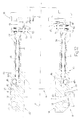
- Each folding member 39 comprises a movable block 41, which has a flat surface 42 and is moved, in use, by an actuating device 43 of feed device 24 to rotate between a rest position (shown in Figure 3 and in the top half of Figure 12 ), in which flat surface 42 and respective suction head 38 define a supporting surface for the flat label 2 to be folded, and a work position (shown in Figure 4 and in the bottom half of Figure 12 ), in which flat surface 42 forms an angle of less than 180°, and in particular of about 90°, with respect to said supporting surface.
- Actuating device 43 comprises an articulated parallelogram 44 ( Figures 3 and 4 ) which links movable block 41 to a rack 45 of a transmission rod 46, so as to rotate movable block 41 about a virtual axis C.
- Articulated parallelogram 44 comprises two cranks 44a fitted in oscillating manner to a supporting body S of gripping assembly 36; one of cranks 44a is integral with a gear 44b meshing with rack 45; and each crank 44a is connected in oscillating manner, by respective pins 44c, 44d to two connecting rods 44e, 44f crosswise to cranks 44a.
- Articulated parallelogram 44 also comprises a crank 44g connected in oscillating manner to connecting rods 44e, 44f by respective pins 44h, 44i.
- Crank 44g is integral with movable block 41, which is substantially semicylindrical and housed in a substantially semicircular seat 41a formed in supporting body S.
- actuating device 43 also comprises a cam system 47 for activating and deactivating folding member 39, and which comprises a substantially circular cam 48 having a first profile 49 with a groove 50; and a substantially circular cam 51 having a second profile 52 with a projection 53 longer than or the same length as groove 50.
- cams 48 and 51 are coaxial with wheel 35, and groove 50 is located at application station 11.
- Actuating device 43 also comprises a known electric motor (not shown) for rotating cam 51 about axis B via a connecting mechanism D (shown partly in Figure 12 ).
- Transmission rod 46 extends substantially parallel to axis B, and comprises two cam followers 54, 55 located at the opposite end of transmission rod 46 to rack 45, and which cooperate with cams 48, 51 respectively.
- Actuating device 43 also comprises a spring 56 coaxial with transmission rod 46, and which exerts pressure on transmission rod 46 to push cam followers 54, 55 towards cams 48, 51.
- cam follower 54 runs along cam 48 to determine the position of rack 45.
- cam follower 54 engages groove 50 at application station 11 to move transmission rod 46 longitudinally. As it does so, transmission rod 46 transmits motion, via rack 45, to articulated parallelogram 44, which in turn rotates movable block 41 about virtual axis C to fold portion 40.
- cam follower 55 engages projection 53 at application station 11 to prevent transmission rod 46 from moving longitudinally, and so disable folding member 39.
- Machine 1 also comprises a cutting device 57 fitted to frame 25 and located along feed path P2 to form a tear line 58 in label 2.
- Cutting device 57 comprises a drum 59 rotating about a respective axis substantially parallel to axis B; and drum 59 is fitted with one or more known blades (not shown); the cutting device 57, in different embodiments, can be deactivated by stopping rotation of drum 59 and/or removing the blades (not shown) from drum 59.
- application unit 30 is fitted to frame 25 by means of a known worm (not shown), which allows the operator to move application unit 30 crosswise - in particular, perpendicularly - to travelling direction A to adjust the position of wheel 35 with respect to hopper 20 and wheel 31, and hence the position of label 2 on respective suction head 38, and the point along label 2 at which it is folded.
- a known worm not shown
- cutting device 57 is fitted integrally to frame 25, or is integral with application unit 30.
- the position of cutting device 57 with respect to hopper 20 and wheel 31 is adjustable independently by moving cutting device 57 crosswise - in particular, perpendicularly - to direction A by means of a respective known worm (not shown) connecting the cutting device to frame 25.
- applicator 15 (and/or applicator 17) ( Figure 9 ) is fitted integrally to frame 25, or is integral with application unit 30.
- the position of applicator 15 (and/or applicator 17) with respect to hopper 20 and wheel 31 is adjustable independently by moving applicator 15 (and/or applicator 17) crosswise - in particular, perpendicularly - to direction A by means, for example, of a respective known worm (not shown) connecting the applicator to frame 25.
- machine 1 is substantially identical to machine 1 described above, and differs solely by also comprising a pretreating device 62 located along given path P1, upstream from gumming device 13, and which provides for surface treating the given portion of each packet 3 to improve retention of the adhesive.
- pretreating device 62 comprises a laser source for directing laser radiation onto said given portion to score and/or remove a surface layer (normally comprising plastic material and/or wax) of packet 3, and so produce a rough and/or porous given portion on packet 3.
- Removing the surface layer of packet 3 reduces the likelihood of adhesive smears forming on packet 3 before, when, and/or after applying label 2.
- a central control unit 60 to switch production from a packet 3 with a folded label 2 (as shown, for example, in Figure 10 ) to a packet 3 with a flat label 2 (as shown, for example, in Figure 11 ), the operator enters the appropriate command in a central control unit 60 via an operator interface (Human Machine Interface - HMI) 61 (e.g. a touch screen, and/or a keyboard, and/or pushbutton panel with or without a screen).
- operator interface Human Machine Interface - HMI
- central control unit 60 operates actuator 27 to move feed assembly 19 (in particular, feed device 24) crosswise to travelling direction A and towards conveying device 10 to adjust the portion of respective packet 3 to which each label 2 is applied.
- central control unit 60 activates the electric motor (not shown) to rotate cam 51 about axis B and align projection 53 with groove 50, thus deactivating folding members 39.
- machine 1 is extremely versatile, by adjusting the position of labels 2 on respective packets 3, and switching rapidly and efficiently from production of a packet 3 with a folded label 2 (as shown, for example, in Figure 10 ) to a packet 3 with a flat label 2 (as shown, for example, in Figure 11 ), and vice versa, thus minimizing labour time and downtime of machine 1.
- some of the longitudinal edges and/or transverse edges of packet 3 may be non-square rounded or bevelled edges.
- the longitudinal edges may be non-square rounded or bevelled edges, or (as in the packet of cigarettes described in Patent Application EP-A1-0764595 ) the major transverse edges may be non-square rounded or bevelled edges.
- some longitudinal edges and transverse edges may be non-square, so as to have non-square rounded or bevelled longitudinal and transverse edges.
- packet 3 may resemble the packet of cigarettes described in Patent Application EP-A1-1066206 ; in which case, the front wall and/or rear wall 6 are/is outwardly convex, with a flat central portion and two curved creased lateral bands.
Landscapes
- Labeling Devices (AREA)
Applications Claiming Priority (1)
| Application Number | Priority Date | Filing Date | Title |
|---|---|---|---|
| IT000129A ITBO20070129A1 (it) | 2007-02-27 | 2007-02-27 | Macchina e metodo per l' applicazione di etichette a pacchetti. |
Publications (3)
| Publication Number | Publication Date |
|---|---|
| EP1964783A2 true EP1964783A2 (de) | 2008-09-03 |
| EP1964783A3 EP1964783A3 (de) | 2008-10-08 |
| EP1964783B1 EP1964783B1 (de) | 2012-09-19 |
Family
ID=39456391
Family Applications (1)
| Application Number | Title | Priority Date | Filing Date |
|---|---|---|---|
| EP08150391A Active EP1964783B1 (de) | 2007-02-27 | 2008-01-18 | Maschine zur Anbringung von Etiketten an Paketen |
Country Status (4)
| Country | Link |
|---|---|
| US (1) | US7946330B2 (de) |
| EP (1) | EP1964783B1 (de) |
| CN (1) | CN101269710B (de) |
| IT (1) | ITBO20070129A1 (de) |
Cited By (4)
| Publication number | Priority date | Publication date | Assignee | Title |
|---|---|---|---|---|
| WO2010121682A1 (de) * | 2009-04-24 | 2010-10-28 | Focke & Co. (Gmbh & Co. Kg) | Vorrichtung und verfahren zum herstellen von packungen für zigaretten |
| ITBO20090494A1 (it) * | 2009-07-28 | 2011-01-29 | Gd Spa | Metodo e apparecchiatura per applicare tagliandi su prodotti di consumo |
| WO2014012956A1 (en) * | 2012-07-18 | 2014-01-23 | Jt International Sa | Tamper evident seal |
| IT202100024059A1 (it) * | 2021-09-20 | 2023-03-20 | Sasib Spa | Macchina e metodo per l’applicazione di bollini a contenitori |
Families Citing this family (14)
| Publication number | Priority date | Publication date | Assignee | Title |
|---|---|---|---|---|
| CN101486392B (zh) * | 2009-03-04 | 2011-01-26 | 岳睿 | 连续快速气动的贴标签的机电设备 |
| DE102011054890A1 (de) * | 2011-10-28 | 2013-05-02 | Krones Aktiengesellschaft | Behälterbehandlungsanlage und Handhabungsvorrichtung |
| EP2712819B1 (de) * | 2012-09-28 | 2016-02-24 | Kronoplus Technical AG | Vorrichtung und Verfahren zum Anbringen von Etiketten auf Kisten |
| ITUB20160589A1 (it) * | 2016-02-09 | 2017-08-09 | Ima Spa | Unita' e metodo per disporre oggetti entro scatole. |
| CN107226250B (zh) * | 2017-06-30 | 2024-04-09 | 浙江隆昂机电设备有限公司 | 烟包税票机 |
| CN107472619A (zh) * | 2017-07-12 | 2017-12-15 | 北京天申正祥科技有限公司 | 一种yb25软盒包装机封签随动装置 |
| DE102017011310A1 (de) * | 2017-12-08 | 2019-06-13 | Focke & Co. (Gmbh & Co. Kg) | Verpackungsmaschine zum Herstellen von Zigarettenpackungen |
| GB201801343D0 (en) | 2018-01-26 | 2018-03-14 | British American Tobacco Investments Ltd | A Pack |
| US20210032013A1 (en) * | 2018-02-09 | 2021-02-04 | British American Tobacco (Investments) Limited | A pack |
| CN109813655A (zh) * | 2019-04-01 | 2019-05-28 | 赣州逸豪新材料股份有限公司 | 一种铜箔全自动质检示损设备 |
| CN112644832B (zh) * | 2020-12-15 | 2022-07-26 | 良忠城精密科技(苏州)有限公司 | 一种全自动贴标机 |
| CN112659639B (zh) * | 2020-12-22 | 2022-11-15 | 杭州金来纸制品有限公司 | 一种精品礼盒及其制造设备 |
| CN115285484B (zh) * | 2022-08-25 | 2023-12-12 | 中建材创新科技研究院有限公司 | 一种石膏板防伪芯片安装装置 |
| CN115489828A (zh) * | 2022-10-05 | 2022-12-20 | 浙江励泰智能机械有限公司 | 一种烟草包装、装盒连线设备 |
Citations (2)
| Publication number | Priority date | Publication date | Assignee | Title |
|---|---|---|---|---|
| EP0764595A1 (de) | 1995-09-25 | 1997-03-26 | G.D Societa' Per Azioni | Steife, mit Scharnierdeckel versehene Verpackung für längliche Elemente, insbesondere für Zigaretten |
| EP1066206A1 (de) | 1999-01-21 | 2001-01-10 | G.D. Societa' per Aziono | Steife klappdeckelverpackung |
Family Cites Families (15)
| Publication number | Priority date | Publication date | Assignee | Title |
|---|---|---|---|---|
| US3682743A (en) * | 1970-05-22 | 1972-08-08 | Syncro Motion Corp | Labelling machine for pressure sensitive labels |
| IT1070190B (it) * | 1976-12-13 | 1985-03-29 | Gd Spa | Dispositivo di tipo universale per l applicazione dell etichettina o bollino di stato ai pacchetti di sigarette ad esempio del tipo a coperchio incernierato hinged lid |
| DE3006322A1 (de) * | 1980-02-20 | 1981-08-27 | Focke & Co, 2810 Verden | Vorrichtung zum anbringen von banderolen auf quaderfoermige zigaretten-packungen |
| US4354894A (en) * | 1981-08-04 | 1982-10-19 | Brown & Williamson Tobacco Corporation | Apparatus for depositing a coupon on a package |
| US4460428A (en) * | 1982-03-31 | 1984-07-17 | Teraoka Seiko Co. Ltd. | Scaling and labeling apparatus |
| DE3301439A1 (de) | 1983-01-18 | 1984-07-19 | Bizerba-Werke Wilhelm Kraut GmbH & Co KG, 7460 Balingen | Vorrichtung zum aufbringen von klebeetiketten auf gegenstaende |
| JPS6169534A (ja) | 1984-09-11 | 1986-04-10 | 株式会社 サト− | ラベル自動貼付機 |
| US4857121A (en) | 1988-03-31 | 1989-08-15 | Hobart Corporation | Method for printing and applying labels |
| IT1235977B (it) * | 1989-12-18 | 1992-12-15 | Gd Spa | Dispositivo per l'applicazione di fascette a pacchetti sostanzialmenteparallelepipedi |
| DE4135106C2 (de) * | 1991-10-24 | 1993-09-30 | Bizerba Werke Kraut Kg Wilh | Vorrichtung zum Aufbringen mehrerer Etiketten |
| IT1264296B1 (it) * | 1993-12-23 | 1996-09-23 | Gd Spa | Apparecchiatura per l'applicazione di etichette di sigillo a contenitori |
| DE19711108C1 (de) * | 1997-03-06 | 1998-09-24 | Reemtsma H F & Ph | Verfahren zum Aufbringen einer Steuerbanderole auf eine Zigarettenpackung |
| IT1304784B1 (it) * | 1998-12-15 | 2001-03-29 | Gd Spa | Metodo per la realizzazione di pacchetti di sigarette ed impianto perl'attuazione di tale metodo. |
| IT1310460B1 (it) * | 1999-09-01 | 2002-02-18 | Gd Spa | Dispositivo gommatore . |
| ITBO20030672A1 (it) * | 2003-11-13 | 2005-05-14 | Gd Spa | Dispositivo per la piegatura di un foglio |
-
2007
- 2007-02-27 IT IT000129A patent/ITBO20070129A1/it unknown
-
2008
- 2008-01-18 EP EP08150391A patent/EP1964783B1/de active Active
- 2008-01-21 US US12/017,084 patent/US7946330B2/en not_active Expired - Fee Related
- 2008-01-22 CN CN200810088178.0A patent/CN101269710B/zh not_active Expired - Fee Related
Patent Citations (2)
| Publication number | Priority date | Publication date | Assignee | Title |
|---|---|---|---|---|
| EP0764595A1 (de) | 1995-09-25 | 1997-03-26 | G.D Societa' Per Azioni | Steife, mit Scharnierdeckel versehene Verpackung für längliche Elemente, insbesondere für Zigaretten |
| EP1066206A1 (de) | 1999-01-21 | 2001-01-10 | G.D. Societa' per Aziono | Steife klappdeckelverpackung |
Cited By (8)
| Publication number | Priority date | Publication date | Assignee | Title |
|---|---|---|---|---|
| WO2010121682A1 (de) * | 2009-04-24 | 2010-10-28 | Focke & Co. (Gmbh & Co. Kg) | Vorrichtung und verfahren zum herstellen von packungen für zigaretten |
| ITBO20090494A1 (it) * | 2009-07-28 | 2011-01-29 | Gd Spa | Metodo e apparecchiatura per applicare tagliandi su prodotti di consumo |
| EP2279955A1 (de) * | 2009-07-28 | 2011-02-02 | G.D S.p.A. | Verfahren und Vorrichtung zum Aufbringen von Etiketten auf Gegenstände |
| WO2014012956A1 (en) * | 2012-07-18 | 2014-01-23 | Jt International Sa | Tamper evident seal |
| US9365312B2 (en) | 2012-07-18 | 2016-06-14 | Jt International Sa | Tamper evident seal |
| EA029872B1 (ru) * | 2012-07-18 | 2018-05-31 | ДжейТи ИНТЕРНЭШНЛ СА | Упаковка |
| IT202100024059A1 (it) * | 2021-09-20 | 2023-03-20 | Sasib Spa | Macchina e metodo per l’applicazione di bollini a contenitori |
| WO2023042103A1 (en) * | 2021-09-20 | 2023-03-23 | Sasib S.P.A. | Machine and method for applying stamps to containers |
Also Published As
| Publication number | Publication date |
|---|---|
| US7946330B2 (en) | 2011-05-24 |
| CN101269710A (zh) | 2008-09-24 |
| US20080202681A1 (en) | 2008-08-28 |
| EP1964783A3 (de) | 2008-10-08 |
| ITBO20070129A1 (it) | 2007-05-29 |
| EP1964783B1 (de) | 2012-09-19 |
| CN101269710B (zh) | 2012-11-07 |
Similar Documents
| Publication | Publication Date | Title |
|---|---|---|
| EP1964783B1 (de) | Maschine zur Anbringung von Etiketten an Paketen | |
| CA2271141C (en) | Roll-fed labelling apparatus | |
| CA2759823C (en) | Device and method for producing packages for cigarettes | |
| US20120204513A1 (en) | Modular unit for applying opening devices to packages of pourable food products | |
| US4922775A (en) | Device for cutting contoured labels | |
| DE60224714T2 (de) | Verfahren zum Verpacken von Zigaretten in Weichpackungen | |
| RU2223898C2 (ru) | Способ непрерывной упаковки изделия и устройство для его осуществления | |
| US20230173781A1 (en) | Forming unit and method for forming a container and packing apparatus with such a forming unit | |
| KR20170002557A (ko) | 라벨 부착 기계 | |
| GB1561181A (en) | Process and apparatus for the manufacture of filled closedcontainers | |
| US8417369B2 (en) | Device for machining continuously successively transported, flat objects or an almost endless web of material | |
| US20060054670A1 (en) | Pack with a tear strip and device for production thereof | |
| US5535573A (en) | Apparatus (blank unit) for feeding blanks to an article which is to be wrapped | |
| US5674542A (en) | Apparatus for the production of blanks for collars in hinge-lid packs with rounded or polygonal longitudinal edges | |
| US7192502B2 (en) | Method and device for applying a label to a packet | |
| US2243633A (en) | Soap wrapping machine | |
| EP2279955B1 (de) | Verfahren und Vorrichtung zum Aufbringen von Etiketten auf Gegenstände | |
| IT201800006434A1 (it) | Macchina e procedimento per l'etichettatura di contenitori. | |
| EP0972706A1 (de) | Verpackungsmaschine zum Einwickeln eines Gegenstandes | |
| ITBO970152A1 (it) | Apparecchiatura per l'alimentazione di un film di materiale termoforma bile in macchine confezionatrici di prodotti in blister e simili | |
| EP3434608B1 (de) | Faltverfahren und -vorrichtung | |
| KR100536306B1 (ko) | 포장기용 가이드장치 | |
| WO2017137079A1 (fr) | Unité d'assemblage et/ou de traitements de composants | |
| EP0888875A1 (de) | Vorrichtung zum Aufbringen eines Aufreissstreifens |
Legal Events
| Date | Code | Title | Description |
|---|---|---|---|
| PUAI | Public reference made under article 153(3) epc to a published international application that has entered the european phase |
Free format text: ORIGINAL CODE: 0009012 |
|
| AK | Designated contracting states |
Kind code of ref document: A2 Designated state(s): AT BE BG CH CY CZ DE DK EE ES FI FR GB GR HR HU IE IS IT LI LT LU LV MC MT NL NO PL PT RO SE SI SK TR |
|
| AX | Request for extension of the european patent |
Extension state: AL BA MK RS |
|
| PUAL | Search report despatched |
Free format text: ORIGINAL CODE: 0009013 |
|
| AK | Designated contracting states |
Kind code of ref document: A3 Designated state(s): AT BE BG CH CY CZ DE DK EE ES FI FR GB GR HR HU IE IS IT LI LT LU LV MC MT NL NO PL PT RO SE SI SK TR |
|
| AX | Request for extension of the european patent |
Extension state: AL BA MK RS |
|
| 17P | Request for examination filed |
Effective date: 20090407 |
|
| AKX | Designation fees paid |
Designated state(s): CH DE GB LI NL |
|
| 17Q | First examination report despatched |
Effective date: 20090529 |
|
| RTI1 | Title (correction) |
Free format text: MACHINE FOR APPLYING LABELS TO PACKETS |
|
| GRAP | Despatch of communication of intention to grant a patent |
Free format text: ORIGINAL CODE: EPIDOSNIGR1 |
|
| GRAS | Grant fee paid |
Free format text: ORIGINAL CODE: EPIDOSNIGR3 |
|
| GRAA | (expected) grant |
Free format text: ORIGINAL CODE: 0009210 |
|
| AK | Designated contracting states |
Kind code of ref document: B1 Designated state(s): CH DE GB LI NL |
|
| REG | Reference to a national code |
Ref country code: GB Ref legal event code: FG4D |
|
| REG | Reference to a national code |
Ref country code: CH Ref legal event code: EP |
|
| REG | Reference to a national code |
Ref country code: DE Ref legal event code: R096 Ref document number: 602008018834 Country of ref document: DE Effective date: 20121115 |
|
| REG | Reference to a national code |
Ref country code: CH Ref legal event code: NV Representative=s name: ANDRE ROLAND S.A., CH |
|
| REG | Reference to a national code |
Ref country code: NL Ref legal event code: T3 |
|
| PLBE | No opposition filed within time limit |
Free format text: ORIGINAL CODE: 0009261 |
|
| STAA | Information on the status of an ep patent application or granted ep patent |
Free format text: STATUS: NO OPPOSITION FILED WITHIN TIME LIMIT |
|
| 26N | No opposition filed |
Effective date: 20130620 |
|
| REG | Reference to a national code |
Ref country code: DE Ref legal event code: R097 Ref document number: 602008018834 Country of ref document: DE Effective date: 20130620 |
|
| PGFP | Annual fee paid to national office [announced via postgrant information from national office to epo] |
Ref country code: CH Payment date: 20140129 Year of fee payment: 7 |
|
| PGFP | Annual fee paid to national office [announced via postgrant information from national office to epo] |
Ref country code: NL Payment date: 20150126 Year of fee payment: 8 |
|
| PGFP | Annual fee paid to national office [announced via postgrant information from national office to epo] |
Ref country code: GB Payment date: 20150127 Year of fee payment: 8 |
|
| REG | Reference to a national code |
Ref country code: CH Ref legal event code: PL |
|
| PG25 | Lapsed in a contracting state [announced via postgrant information from national office to epo] |
Ref country code: CH Free format text: LAPSE BECAUSE OF NON-PAYMENT OF DUE FEES Effective date: 20150131 Ref country code: LI Free format text: LAPSE BECAUSE OF NON-PAYMENT OF DUE FEES Effective date: 20150131 |
|
| GBPC | Gb: european patent ceased through non-payment of renewal fee |
Effective date: 20160118 |
|
| REG | Reference to a national code |
Ref country code: NL Ref legal event code: MM Effective date: 20160201 |
|
| PG25 | Lapsed in a contracting state [announced via postgrant information from national office to epo] |
Ref country code: GB Free format text: LAPSE BECAUSE OF NON-PAYMENT OF DUE FEES Effective date: 20160118 |
|
| PG25 | Lapsed in a contracting state [announced via postgrant information from national office to epo] |
Ref country code: NL Free format text: LAPSE BECAUSE OF NON-PAYMENT OF DUE FEES Effective date: 20160201 |
|
| PGFP | Annual fee paid to national office [announced via postgrant information from national office to epo] |
Ref country code: DE Payment date: 20250129 Year of fee payment: 18 |