EP1964976B1 - Balayeuse à projection par le haut - Google Patents
Balayeuse à projection par le haut Download PDFInfo
- Publication number
- EP1964976B1 EP1964976B1 EP07004157A EP07004157A EP1964976B1 EP 1964976 B1 EP1964976 B1 EP 1964976B1 EP 07004157 A EP07004157 A EP 07004157A EP 07004157 A EP07004157 A EP 07004157A EP 1964976 B1 EP1964976 B1 EP 1964976B1
- Authority
- EP
- European Patent Office
- Prior art keywords
- sweeping
- sweeping roller
- support element
- sweeper
- roller
- Prior art date
- Legal status (The legal status is an assumption and is not a legal conclusion. Google has not performed a legal analysis and makes no representation as to the accuracy of the status listed.)
- Not-in-force
Links
Images


Classifications
-
- E—FIXED CONSTRUCTIONS
- E01—CONSTRUCTION OF ROADS, RAILWAYS, OR BRIDGES
- E01H—STREET CLEANING; CLEANING OF PERMANENT WAYS; CLEANING BEACHES; DISPERSING OR PREVENTING FOG IN GENERAL CLEANING STREET OR RAILWAY FURNITURE OR TUNNEL WALLS
- E01H1/00—Removing undesirable matter from roads or like surfaces, with or without moistening of the surface
- E01H1/02—Brushing apparatus, e.g. with auxiliary instruments for mechanically loosening dirt
- E01H1/04—Brushing apparatus, e.g. with auxiliary instruments for mechanically loosening dirt taking- up the sweepings, e.g. for collecting, for loading
- E01H1/045—Brushing apparatus, e.g. with auxiliary instruments for mechanically loosening dirt taking- up the sweepings, e.g. for collecting, for loading the loading means being a rotating brush with horizontal axis
Definitions
- the invention relates to an overhead headlamp sweeper according to the preamble of claim 1.
- the pivot arms of the sweeping roller based on the frame of the machine slidably content Erten holding elements, which have an inclined support surface and which are displaceable by means of a Bowden cables containing actuating mechanism in the axial direction of the sweeper.
- a Bowden cables containing actuating mechanism in the axial direction of the sweeper.
- the holding elements are held by Bowden cables of the actuating device in a defined position, so that in the case of an unused sweeping roller, the support of the pivot arms of the sweeping roller are supported on the front and thus high end of the retaining surfaces of the retaining elements.
- this rear position of the holding elements with respect to the frame of the sweeper is the holder of the dirt container in its caused by the support rods, the rearmost position.
- the adjustment in this prior art overhead head sweeper fulfills the task of adjusting the longitudinal axis of the sweeping roller and the lower edge of the inlet opening of the dirt container when shortening the bristles in operation completely satisfactory.
- it is composed of relatively many individual parts, and the longitudinal guides for the holding elements can be difficult due to the dusty ambient air.
- an overhead headlamp sweeper of the type mentioned above is characterized according to the invention by the characteristics of the license plate.
- the support of the pivot arms of the sweeping roller in the sweeping position causing cable is connected to an actuating mechanism, with which at least one support element for the dirt container is coupled. Therefore, if the adjusting mechanism for adjusting the position of the longitudinal axis of the sweeping roller actuated and thereby the effective length of the cable is increased, there is also a corresponding displacement of the support the dirt container, so that the lower carcass of the inlet opening of the dirt container is adjusted according to the changed position of the sweeping roller.
- the cable is preferably a Bowden cable, the sleeve sections are arranged close to the movable support surface with respect to the rope.
- the adjusting mechanism may comprise a rotatable, but axially non-supported mounted screw spindle, on which a non-rotatable relative to the machine frame adjusting nut sits, and the cable can be firmly connected to the adjusting nut, with a linkage for the displacement of a support member may be coupled.
- the screw spindle is preferably arranged substantially perpendicular to the support plane, and it may have a handle element for manual rotation at one end. By turning the screw the adjusting nut is displaced along the screw and so changed the effective length of the cable connected to the adjusting nut.
- Such a construction is sturdy and simple, and it allows for easy and accurate manual adjustment.
- the at least one support element for supporting the dirt container may have a curved support surface and be pivotally supported on machine frame, and on the at least one support member may engage a push rod which is coupled via a pivot lever with the adjusting nut.
- Upon rotation of the screw for adjusting the sweeping mirror of the sweeping roller then takes place via the pivot lever and the push rod pivoting of the at least one support element, so that another area of the curved support surface is effective.
- the shape of the support surface can be adapted to the desired Nachstellverlauf the dirt container.
- the at least one support member may be provided on a side portion of the machine frame, and another, with this rigidly coupled and a corresponding support surface exhibiting support member may be disposed on the opposite side region of the machine frame, so that the relatively heavy Dirt container is supported in its two outdoor areas.
- the one end of the cable can be coupled to an actuating lever which, when actuated in one direction, the end of the cable so shifts so that the support surface is depressed and thereby the sweeping roller is raised to the position for travel operation.
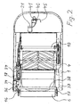
- FIG. 1 illustrated overhead head sweeper has in the usual way a frame 1, which carries the various components and units of the sweeper, which is movable on wheels, of which only the wheel 2 is shown.
- the sweeper has an area 3 for the driver, wherein in this area a driver's seat and the usual controls are arranged.
- In the front region of the sweeper is provided in the usual way not interesting for the present case, but usual side brush 5.
- the sweeper has a conventional cylindrical sweeping roller 4, which is supported on not shown, coupled to each other via the axis 10 pivoting arms, so that a pivoting of the pivot arms pivoting of the other pivot arm in the same direction and to the same extent result, whereby the Longitudinal axis 4 'of the sweeping roller 4 is raised or lowered along a curved path.
- the Figures 3 and 4 are also parts of the usual, not interesting here drive mechanism for rotating the sweeping roller 4 shown in the counterclockwise direction.
- the dirt container 6 is connected to two arms 16, 17, which via an axis 19 (FIG. FIG. 1 ) are rigidly coupled together, held, and by activation of a working cylinder 18 (FIG. FIG. 3 ) are pivoted to a raised position, which allows the emptying.
- the one of the sweeping roller 4-holding pivot arms in the form of a two-armed lever, and its longitudinal axis 4 'of the sweeping roller 4 facing away from arm 7 carries at its outer end a roller forming a bearing surface 11.
- the part 20 extends a Bowden cable , whose sheath 21 is interrupted in this area and attached here at 21 "fixed to the frame or at 21 'fixed to the arm 7.
- the Bowden cable or its rope 20 is firmly connected at the front end with a linkage arrangement, which is kept non-displaceable in sweeping.
- the cable 20 of the Bowden cable runs over a guide roller 22 upwards, where the rear end of the rope 20 fixed to a control nut 27th connected is.
- the adjusting nut 27 is seated on a screw spindle 26, which is arranged on a substantially perpendicular to a support plane formed by the support surface of the wheels of the sweeper extending and fixed to a frame 1 carrier 25 rotatable, but axially non-displaceable.
- a handle member 26 ' is provided, which allows the rotation of the screw by hand.
- the adjusting nut 27 has at its outer ends pin elements 28 which in perpendicular guide slots of the carrier 25 (FIG. FIG.
- a U-shaped pivot lever 29 On a rotatably mounted in the carrier 25 axis 30 is a U-shaped pivot lever 29. The provided with slots 31 of the pivot lever is coupled to the adjusting nut 27. On the other end of the pivot lever 29 is a stub axle with a joint to which the push rod 34 is connected. This extends rearwardly and is coupled to an arm 35 which is fixedly connected to a support member 36. The support member 36 is connected via the axis 38 with a further support member 37 which is located in the region of the opposite side of the frame 1.
- the support members 36 and 37 have curved support surfaces against which the dirt container 6 supporting arms 16 and 17 abut in sweeping, so that by the orientation of the support members 36 and 37 in cooperation with the shape of their support surface, the position of the dirt container 6 and in particular the position the lower edge 15 of the receiving opening of the dirt container with respect to the outer circumference of the sweeping roller 4 is fixed.
- sweeping operation determines the effective length of the rope 20 by its engagement with the bearing surface formed by the roller 11, the pivotal position of the sweeping roller 4 supporting pivot arms and thus the so-called sweeping mirror, i. the area in which the free ends of the bristles of the sweeping roller 4 come into engagement with the floor to be cleaned.
- the position of the front edge 15 with respect to the circumference of the sweeping roller 4 is determined by the screw shaft 26 and the push rod 34 connected to it via the adjusting nut 27 and the pivot lever 29 in cooperation with the shape of the support surfaces of the support elements 36 and 37, so that both an optimal dimension of the formed between broom 4 and tunnel wall 8 Ben tunnel as well as an optimal distance of the front edge 15 of the receiving opening of the dirt container 6 with respect to the outer periphery of the sweeping roller 4 results.
- the front end of the cable 20 of the Bowden cable is connected to an eyelet 42 on a bolt 43 (FIG. FIGS. 7 and 8th ), which is part of the intermediate lever 41.
- This intermediate lever is mounted on a frame 45 mounted on the frame 1, rod-shaped actuating element 40, which has at its upper end an angled grip portion which, as in FIG. 1 indicated, is directly accessible to the driver.
- the driver rotates the angled to a handle portion actuator 40 counterclockwise ( FIG. 7 ), so attached to the intermediate lever 41 end of the cable 20 of the Bowden cable is displaced forward.
Landscapes
- Engineering & Computer Science (AREA)
- Architecture (AREA)
- Civil Engineering (AREA)
- Structural Engineering (AREA)
- Cleaning In General (AREA)
Claims (8)
- Balayeuse à projection par le haut, comportant- un châssis (1) pour la fixation des roues (2), dont les zones entrant en contact avec le sol à nettoyer sont situées dans un plan d'appui, et des autres éléments de la balayeuse,- un rouleau de balayage (4) cylindrique, qui est apte à tourner autour de son axe longitudinal, qui est fixé sur des bras pivotants réglables conjointement et dont les brosses, situées en cours de service dans la zone de la surface de balayage, se déplacent dans la direction d'avancement de la balayeuse,- une paroi (8) délimitant le tunnel de balayage et couvrant la zone avant et la zone supérieure du rouleau de balayage (4), et- un bac de réception des déchets (6), qui est monté en aval du rouleau de balayage (4) et dont l'ouverture d'admission est orientée vers la sortie du tunnel de balayage et dont le bord inférieur (15) est adjacent au rouleau de balayage (4) et lequel, dans sa position de réception des déchets, est maintenu en position soutenue par rapport au rouleau de balayage (4), par au moins un élément de soutien (36) réglable,- sachant que pour le réglage de la surface de balayage, les bras pivotants du rouleau de balayage (4) sont amenés en pivotement par le réglage d'un câble de traction (20) et, dans ce cas, il se produit également une variation de la position dudit au moins un élément de soutien (36), de telle sorte que le réglage de la surface de balayage est lié au réglage d'une distance optimale entre le rouleau de balayage (4) et la paroi (8) du tunnel de balayage et au réglage de la distance optimale entre l'ouverture d'admission du bac de réception des déchets (6) et le rouleau de balayage (4),caractérisée
en ce que l'un des bras pivotants du rouleau de balayage (4) est un levier à deux bras qui, sur son bras (7) éloigné de l'axe longitudinal (4') du rouleau de balayage (4), comporte une surface de pose (11) pour le câble de traction (20), dont une extrémité est immobilisée lorsque le rouleau de balayage (4) est en position de balayage abaissée et dont l'autre extrémité est reliée au mécanisme de réglage, de telle sorte que le câble de traction (20), sous l'effet du contact avec la surface de pose (11), maintient les bras pivotants dans la position pour la position de balayage du rouleau de balayage (4), et en ce que au moins un élément de soutien (36) est couplé à un mécanisme de réglage, de telle sorte que le réglage de celui-ci fait varier la longueur active du câble de traction (20) et déplace de manière correspondante ledit au moins un élément de soutien (36), - Balayeuse à projection par le haut selon la revendication 1, caractérisée en ce que le câble de traction est un câble sous gaine (20, 21), dont les tronçons de gaine (21') sont disposés de manière fixe par rapport au câble (20) à proximité de la surface de pose (11).
- Balayeuse à projection par le haut selon la revendication 1 ou 2, caractérisée en ce que le mécanisme de réglage est une broche filetée (26) rotative, mais immobile dans la direction axiale, sur laquelle est posé un écrou de réglage (27) immobile en rotation par rapport au châssis (1) de la balayeuse, et en ce que le câble de traction (20) est relié de manière fixe à l'écrou de réglage (27) et une timonerie (29, 34) est reliée à ce dernier en vue de déplacer ledit au moins un élément de soutien (36).
- Balayeuse à projection par le haut selon la revendication 3, caractérisée en ce que la broche filetée (26) est disposée sensiblement perpendiculairement au plan de soutien.
- Balayeuse à projection par le haut selon la revendication 3 ou 4, caractérisée en ce qu'au niveau d'une extrémité de la broche filetée (26), il est prévu un élément de préhension (26') pour la rotation manuelle de la broche filetée (26).
- Balayeuse à projection par le haut selon l'une quelconque des revendications 3 à 5, caractérisée en ce que ledit au moins un élément de soutien (36) comporte une surface d'appui en forme de came et est maintenu de manière pivotante sur le châssis de la balayeuse, et en ce qu'une tige de poussée (34), qui est couplée à l'écrou de réglage (27) par l'intermédiaire d'un levier pivotant (29), entre en contact avec ledit au moins un élément de soutien (36).
- Balayeuse à projection par le haut selon la revendication 6, caractérisée en ce que ledit au moins un élément de soutien (36) est prévu sur une zone latérale du châssis (1) de la balayeuse, et en ce qu'un autre élément de soutien (37), muni d'une surface d'appui correspondante et couplé de manière rigide à celui-ci, est disposé sur la zone latérale opposée du châssis (1) de la balayeuse.
- Balayeuse à projection par le haut selon l'une quelconque des revendications 1 à 6, caractérisée en ce que l'une des extrémités du câble de traction (20) est couplée à un élément de manoeuvre (40), par lequel le câble de traction (20) peut être déplacé entre une position pour le mode balayage et une position pour le transport, dans laquelle le rouleau de balayage (4) est soulevé du sol.
Priority Applications (3)
| Application Number | Priority Date | Filing Date | Title |
|---|---|---|---|
| EP07004157A EP1964976B1 (fr) | 2007-02-28 | 2007-02-28 | Balayeuse à projection par le haut |
| DE502007002030T DE502007002030D1 (de) | 2007-02-28 | 2007-02-28 | Überkopfwerfer-Kehrmaschine |
| US12/029,697 US8079107B2 (en) | 2007-02-28 | 2008-02-12 | Overhead throwing sweeping machine |
Applications Claiming Priority (1)
| Application Number | Priority Date | Filing Date | Title |
|---|---|---|---|
| EP07004157A EP1964976B1 (fr) | 2007-02-28 | 2007-02-28 | Balayeuse à projection par le haut |
Publications (2)
| Publication Number | Publication Date |
|---|---|
| EP1964976A1 EP1964976A1 (fr) | 2008-09-03 |
| EP1964976B1 true EP1964976B1 (fr) | 2009-11-18 |
Family
ID=38235241
Family Applications (1)
| Application Number | Title | Priority Date | Filing Date |
|---|---|---|---|
| EP07004157A Not-in-force EP1964976B1 (fr) | 2007-02-28 | 2007-02-28 | Balayeuse à projection par le haut |
Country Status (3)
| Country | Link |
|---|---|
| US (1) | US8079107B2 (fr) |
| EP (1) | EP1964976B1 (fr) |
| DE (1) | DE502007002030D1 (fr) |
Families Citing this family (11)
| Publication number | Priority date | Publication date | Assignee | Title |
|---|---|---|---|---|
| US8769755B2 (en) * | 2009-11-09 | 2014-07-08 | Tennant Company | Side brush assembly mechanism |
| CN102011372B (zh) * | 2010-11-29 | 2012-04-25 | 江苏紫光吉地达环境科技股份有限公司 | 一种隧道吹扫除尘车 |
| KR101622331B1 (ko) | 2011-06-17 | 2016-05-31 | 알프레드 캐르혀 게엠베하 운트 컴파니. 카게 | 스위핑 차량 |
| KR20140026386A (ko) * | 2011-06-17 | 2014-03-05 | 알프레드 캐르혀 게엠베하 운트 컴파니. 카게 | 브러시 디스크 조절기를 갖는 청소 차량 |
| US8978190B2 (en) * | 2011-06-28 | 2015-03-17 | Karcher North America, Inc. | Removable pad for interconnection to a high-speed driver system |
| CN105640444A (zh) * | 2016-02-14 | 2016-06-08 | 蒙城县雅熙电动车有限公司 | 微型厂区清扫环卫车 |
| DE102018008269A1 (de) | 2018-04-13 | 2019-10-17 | Hako Gmbh | Straßenkehrmaschine |
| CN108749928B (zh) * | 2018-06-05 | 2020-06-26 | 广东纵行科技有限公司 | 一种车架总成 |
| DE102019112257B4 (de) * | 2019-05-10 | 2022-04-28 | Franziska Mehlhorn | Vorrichtung zum Abmisten von Höfen und Wiesen |
| CN110424321A (zh) * | 2019-07-22 | 2019-11-08 | 安徽名扬刷业有限公司 | 一种扫雪刷 |
| CN110616664A (zh) * | 2019-09-12 | 2019-12-27 | 安徽名扬刷业有限公司 | 一种软连接高强度扫雪刷 |
Family Cites Families (5)
| Publication number | Priority date | Publication date | Assignee | Title |
|---|---|---|---|---|
| GB440117A (en) * | 1934-06-20 | 1935-12-20 | James Edgar Hobbs | Improvements in sweeping machines for roads or the like |
| DE19715435C2 (de) * | 1997-04-08 | 2000-02-03 | Hako Gmbh & Co | Überkopfwerfer-Reinigungsmaschine |
| US6035479A (en) * | 1998-05-12 | 2000-03-14 | Tennant Company | Sweeper with auxiliary brush and auxiliary lip |
| FR2784127B1 (fr) * | 1998-10-05 | 2000-11-24 | Bugnot Ets | Engin de nettoyage de voirie par brossage |
| US7082639B2 (en) * | 2001-10-19 | 2006-08-01 | Tennant Company | Brush optimizer |
-
2007
- 2007-02-28 EP EP07004157A patent/EP1964976B1/fr not_active Not-in-force
- 2007-02-28 DE DE502007002030T patent/DE502007002030D1/de active Active
-
2008
- 2008-02-12 US US12/029,697 patent/US8079107B2/en not_active Expired - Fee Related
Also Published As
| Publication number | Publication date |
|---|---|
| US20080201878A1 (en) | 2008-08-28 |
| EP1964976A1 (fr) | 2008-09-03 |
| US8079107B2 (en) | 2011-12-20 |
| DE502007002030D1 (de) | 2009-12-31 |
Similar Documents
| Publication | Publication Date | Title |
|---|---|---|
| EP1964976B1 (fr) | Balayeuse à projection par le haut | |
| DE3528038C2 (fr) | ||
| DE4100333A1 (de) | Mechanismus zur hoeheneinstellung von bodenreinigungsgeraeten | |
| EP2739196A1 (fr) | Machine mobile de nettoyage des sols et procédé permettant de faire fonctionner une machine de nettoyage des sols | |
| EP1531202B1 (fr) | Balayeuse | |
| DE4429996A1 (de) | Kehrfahrzeug | |
| EP1529431B1 (fr) | Semoir | |
| DE19715435C2 (de) | Überkopfwerfer-Reinigungsmaschine | |
| EP3415067B1 (fr) | Dispositif formant balai latéral pour une machine de nettoyage du sol | |
| DE69307127T2 (de) | Heuwendemaschine | |
| DE102018104749B4 (de) | Kehrmaschine | |
| DE60102095T2 (de) | Motorangetriebene Kehrmaschine | |
| EP1816265B1 (fr) | Balayeuse pour nettoyer des voies, des routes ou surfaces utilisables similaires | |
| DE19637685C2 (de) | Reinigungsmaschine mit einschwenkbarer Seitenbürste | |
| DE9421625U1 (de) | Kehrfahrzeug | |
| EP0391010A1 (fr) | Balayeuse | |
| EP4192318B1 (fr) | Machine de nettoyage pour le sol et procédé pour faire fonctionner une machine de nettoyage pour le sol | |
| EP1817953A2 (fr) | Appareil d'entretien de la pelouse, du jardin ou du terrain et dispositif de réglage en hauteur | |
| DE19649962C2 (de) | Fahrbare Reinigungsmaschine mit Kehreinheit und Scheuereinheit | |
| DE20120122U1 (de) | Einsammelnde Bürstmaschine | |
| DE102010008601A1 (de) | Heuwerbungsmaschine | |
| EP1970492B1 (fr) | Balayeuse avec un dispositif de commande pour ses composants mécaniques | |
| DE69105636T2 (de) | Kraftfahrzeug zum Reinigen grosser Oberflächen. | |
| DE4202064C2 (de) | Handgeführte, fahrbare Bodenreinigungsmaschine | |
| DE29814661U1 (de) | Handverfahrbares Gerät mit absenkbarem Werkzeug |
Legal Events
| Date | Code | Title | Description |
|---|---|---|---|
| PUAI | Public reference made under article 153(3) epc to a published international application that has entered the european phase |
Free format text: ORIGINAL CODE: 0009012 |
|
| AK | Designated contracting states |
Kind code of ref document: A1 Designated state(s): AT BE BG CH CY CZ DE DK EE ES FI FR GB GR HU IE IS IT LI LT LU LV MC NL PL PT RO SE SI SK TR |
|
| AX | Request for extension of the european patent |
Extension state: AL BA HR MK RS |
|
| 17P | Request for examination filed |
Effective date: 20080912 |
|
| GRAP | Despatch of communication of intention to grant a patent |
Free format text: ORIGINAL CODE: EPIDOSNIGR1 |
|
| AKX | Designation fees paid |
Designated state(s): DE FR GB IT |
|
| GRAS | Grant fee paid |
Free format text: ORIGINAL CODE: EPIDOSNIGR3 |
|
| GRAA | (expected) grant |
Free format text: ORIGINAL CODE: 0009210 |
|
| AK | Designated contracting states |
Kind code of ref document: B1 Designated state(s): DE FR GB IT |
|
| REG | Reference to a national code |
Ref country code: GB Ref legal event code: FG4D Free format text: NOT ENGLISH |
|
| REF | Corresponds to: |
Ref document number: 502007002030 Country of ref document: DE Date of ref document: 20091231 Kind code of ref document: P |
|
| PLBE | No opposition filed within time limit |
Free format text: ORIGINAL CODE: 0009261 |
|
| STAA | Information on the status of an ep patent application or granted ep patent |
Free format text: STATUS: NO OPPOSITION FILED WITHIN TIME LIMIT |
|
| 26N | No opposition filed |
Effective date: 20100819 |
|
| PGRI | Patent reinstated in contracting state [announced from national office to epo] |
Ref country code: IT Effective date: 20110501 |
|
| REG | Reference to a national code |
Ref country code: FR Ref legal event code: PLFP Year of fee payment: 10 |
|
| PGFP | Annual fee paid to national office [announced via postgrant information from national office to epo] |
Ref country code: FR Payment date: 20160108 Year of fee payment: 10 Ref country code: GB Payment date: 20160224 Year of fee payment: 10 |
|
| GBPC | Gb: european patent ceased through non-payment of renewal fee |
Effective date: 20170228 |
|
| REG | Reference to a national code |
Ref country code: FR Ref legal event code: ST Effective date: 20171031 |
|
| PG25 | Lapsed in a contracting state [announced via postgrant information from national office to epo] |
Ref country code: FR Free format text: LAPSE BECAUSE OF NON-PAYMENT OF DUE FEES Effective date: 20170228 |
|
| PG25 | Lapsed in a contracting state [announced via postgrant information from national office to epo] |
Ref country code: GB Free format text: LAPSE BECAUSE OF NON-PAYMENT OF DUE FEES Effective date: 20170228 |
|
| PGFP | Annual fee paid to national office [announced via postgrant information from national office to epo] |
Ref country code: IT Payment date: 20210211 Year of fee payment: 15 |
|
| PGFP | Annual fee paid to national office [announced via postgrant information from national office to epo] |
Ref country code: DE Payment date: 20210216 Year of fee payment: 15 |
|
| REG | Reference to a national code |
Ref country code: DE Ref legal event code: R119 Ref document number: 502007002030 Country of ref document: DE |
|
| PG25 | Lapsed in a contracting state [announced via postgrant information from national office to epo] |
Ref country code: DE Free format text: LAPSE BECAUSE OF NON-PAYMENT OF DUE FEES Effective date: 20220901 |
|
| PG25 | Lapsed in a contracting state [announced via postgrant information from national office to epo] |
Ref country code: IT Free format text: LAPSE BECAUSE OF NON-PAYMENT OF DUE FEES Effective date: 20220228 |