EP1964986A2 - Ab- und Überlaufsystem mit Abdeckplatte - Google Patents
Ab- und Überlaufsystem mit Abdeckplatte Download PDFInfo
- Publication number
- EP1964986A2 EP1964986A2 EP07122570A EP07122570A EP1964986A2 EP 1964986 A2 EP1964986 A2 EP 1964986A2 EP 07122570 A EP07122570 A EP 07122570A EP 07122570 A EP07122570 A EP 07122570A EP 1964986 A2 EP1964986 A2 EP 1964986A2
- Authority
- EP
- European Patent Office
- Prior art keywords
- cover plate
- bearing means
- overflow system
- magnet
- container wall
- Prior art date
- Legal status (The legal status is an assumption and is not a legal conclusion. Google has not performed a legal analysis and makes no representation as to the accuracy of the status listed.)
- Granted
Links
Images

Classifications
-
- E—FIXED CONSTRUCTIONS
- E03—WATER SUPPLY; SEWERAGE
- E03C—DOMESTIC PLUMBING INSTALLATIONS FOR FRESH WATER OR WASTE WATER; SINKS
- E03C1/00—Domestic plumbing installations for fresh water or waste water; Sinks
- E03C1/12—Plumbing installations for waste water; Basins or fountains connected thereto; Sinks
- E03C1/24—Overflow devices for basins or baths
Definitions
- the present invention relates to an overflow and overflow system for sanitary containers, in particular for washstands, sinks, bathtubs and bidets, as well as a cover plate for such a drain and overflow system.
- a variety of drainage and overflow systems for sanitary containers are known in which a passage opening is provided in a container wall, which is in fluid communication with an overflow pipe.
- the overflow pipe is usually fixed by means of screws or similar fastening means on the container wall in the region of the passage opening.
- a disadvantage of this prior art is that the fastening means for fixing the overflow pipe protrude partially into the interior of the container and project slightly towards the container wall.
- the protruding part this is usually the screw head, for example, in a bathtub for the user perceived as unpleasant, if the user would like to lean against said container wall.
- the protruding part may even entail a certain risk of injury.
- a waste and overflow system for sanitary containers in particular for washstands, sinks, bathtubs and bidets, with a A container wall of the sanitary container, having a through opening provided in the container wall, a bearing means connected to the container wall, and a cover plate which at least partially covers the through opening and is detachably connected to the bearing means, the connection between the cover plate and the bearing means is formed such that the compound is releasable under the action of a tensile force on the cover plate in a direction away from the bearing means direction.
- the cover plate may be connected directly or indirectly with the bearing means.
- an additional component can be fixedly connected to or integrally formed with one side of the bearing means, the component being detachably connected to the bearing means.
- cover plate is also used for simplicity if it has on its side facing the bearing means the additional firmly connected to her component.
- the bearing means which may be a bolt or a screw, which is provided in particular for attachment of the overflow pipe is covered by a plate-shaped member which covers the passage opening at least partially, it is ensured that the user with the bearing means not unintentionally comes in contact. On the one hand, this is perceived as pleasant, for example for a bathing person, and at the same time reduces the risk of injury.
- the use of a cover on the bearing means leads at the same time to a more appealing appearance, since the protruding from the container wall part of the bearing means, such as a screw head, is no longer visible.
- the cover plate finds an optimal support on the bearing means and not inadvertently detached from the bearing means can, whereby the protruding from the container wall part of the bearing means would be exposed again, the connection between the cover plate and the bearing means is only under the action of force, namely by the cover plate and bearing means are pulled apart against resistance.
- connection may be a non-positive and / or positive connection and is preferably a magnetic connection.
- a connection ensures on the one hand, that after arranging the bearing means, which is provided for example when screwing an overflow pipe to the container wall inevitably, the cover plate can be fixed with a single handle on the bearing means and can not solve unintentionally after fixing.
- connection between the cover plate and the bearing means for example detent connections, plug-in connections or Velcro connections.
- detent connections for example detent connections, plug-in connections or Velcro connections.
- plug-in connections for example detent connections, plug-in connections or Velcro connections.
- said magnetic connection since this is relatively easy to do and is also wear.
- the cover plate and / or the bearing means on a magnetic portion Magnetic means that the section has a magnetic material or a magnetized material.
- the magnetic portion is formed by a magnet which is connected to the cover plate and / or the bearing means.
- the bearing means for generating the resistance to be overcome for releasing the connections comprises a material which magnetically attracted.
- a material is referred to below for the sake of simplicity as a ferritic material.
- the ferritic material itself may be magnetic.
- the bearing means preferably has a cavity, wherein the magnet is arranged in the cavity.
- the magnet can be connected to the bearing means by gluing or welding. Preferably, however, the magnet is inserted into the cavity by means of a press fit.
- the cover plate or possibly with the cover plate firmly connected component also ferritic or magnetic.
- the bearing means and the cover plate or possibly with the cover plate fixedly connected additional component cooperating with each other centering elements may have as a centering element at its end facing the cover plate a recess, which preferably lies on the central axis of the through hole.
- the cover plate or the magnet connected to the cover plate can have a curvature as a centering element on the side facing the bearing means, which is formed in particular by a circumferential chamfer.
- the surface facing away from the bearing means of the cover plate and the inner surface of the container wall lie in a common plane. This arrangement is particularly pleasant for the user, especially if he wants to lean in the case of a bathtub in the passage opening and the bearing means.
- the cover plate may have various shapes which are ultimately intended to effect at least partial coverage or closure of the passage opening.
- the cover plate may be round, rectangular, square or triangular.
- the shape of the cover plate preferably corresponds to the shape of the passage opening insofar as a uniform gap still remains between the cover plate and the edge of the passage opening. This also provides a sophisticated look.
- the cover plate according to yet another embodiment of the drainage and overflow system according to the invention on a rotation, which is arranged in particular by a bulge, preferably a pin or a nose on the side facing the bearing means side of the cover plate or connected to the cover plate magnet.
- a bulge preferably a pin or a nose on the side facing the bearing means side of the cover plate or connected to the cover plate magnet.
- Such an anti-twist device then preferably cooperates with a stop which is formed in the region of the passage opening, for example on the container wall or on the bearing means.
- a cover plate for a drainage and overflow system for sanitary containers in particular for washstands, sinks, bathtubs and bidets, preferably for an overflow and overflow system as described above was, the Cover plate can at least partially cover a passage opening in a container wall of the sanitary container and is detachably connectable to a bearing means and wherein the cover plate on one side has a magnetic portion.
- Such a cover plate covers a bearing means, for example, a serving for attaching an overflow pipe to the container wall screw, such that it also reduces the risk of injury in addition to a pleasant appearance.
- Such a cover plate may be formed as described above.
- it has on one side an additional component or an Anformung, for example, a magnet which cooperates with the bearing means such that the compound under the action of a tensile force on the cover plate in a direction away from the bearing means direction is solvable.
- the cover plate may have a centering element which ensures that the cover plate can be optimally positioned relative to the passage opening in the container wall.
- the centering element may be a bulge, which is provided on the cover plate or the magnet.
- the curvature is formed in particular by a circumferential chamfer.
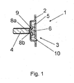
- Fig. 1 shows a first embodiment of an overflow and overflow system 1 for sanitary containers, in the present case for a sink.
- the waste and overflow system 1 has a container wall 2 of the sink, as well as a through opening 3, which is provided in the container wall 2 and is in fluid communication with an overflow pipe, not shown.
- a bearing means 4 which is presently designed as a screw, connected, wherein the bearing means 4 serves for fastening the overflow pipe.
- the screw head of the bearing means 4 is set back slightly relative to the container wall 2 and covered by a cover plate 5 so that the surface of the cover plate 5 facing away from the bearing means 4 and the inner surface of the container wall 2 lie in a common plane.
- a gap 10 is provided between the cover plate 5 and the edge of the passage opening 3, via which the overflow is accomplished.
- the cover plate 5 has on its side facing the bearing means 4 side an additional component, which according to the embodiment in Fig. 1 is designed as a magnet.
- the component or the magnet is firmly glued to the cover plate.
- the cover plate 5 with the as metallic screw trained bearing means 4 releasably connected, such that the connection under the action of a tensile force on the cover plate 5 in a direction away from the bearing means 4 direction is releasable.
- Fig. 1 further shows that the bearing means 4 and the cover plate 5 have cooperating centering elements 8a and 8b.
- a recess is provided as the centering element 8a at the end facing the cover plate 5, which recess lies exactly here on the central axis of the passage opening 3.
- the recess is the attack for a screwing tool.
- conventional screws can be used as storage means for the waste and overflow system 1 according to the invention.
- the magnet 6 connected to the cover plate 5 has, as a centering element 8b on the side facing the bearing means 4, a curvature, which is formed here by a circumferential chamfer 9.
- the curvature formed by the chamfer 9 penetrates during assembly in the corresponding recess on the bearing means 4 and on the one hand ensures that the cover plate 5 is arranged symmetrically to the through hole 3 and at the same time the surface of the cover plate 5 and the inner surface of the container wall 2 in one common plane.
- Fig. 2 shows an alternative embodiment, which basically has a similar structure as the Embodiment from Fig. 1 Has. However, in the present case, the magnetic portion, so the magnet 6, and cooperating with the magnet 6 counterpart to the variant in Fig. 1 reversed.
- the bearing means is formed as a hollow screw, wherein a magnet 6 is arranged in the cavity 7 of the bearing means 4.
- a ferritic component is formed in the present case, which cooperates with the arranged in the cavity 7 magnet 6 such that the connection between the cover plate 5 and the bearing means 4 under the action of a tensile force on the cover plate 5 in a direction away from the bearing means 4 direction is solvable.
Landscapes
- Engineering & Computer Science (AREA)
- Environmental & Geological Engineering (AREA)
- Health & Medical Sciences (AREA)
- Life Sciences & Earth Sciences (AREA)
- Hydrology & Water Resources (AREA)
- Public Health (AREA)
- Water Supply & Treatment (AREA)
- Sink And Installation For Waste Water (AREA)
Abstract
Description
- Die vorliegende Erfindung betrifft ein Ab- und Überlaufsystem für sanitäre Behälter, insbesondere für Waschtische, Spülen, Badewannen und Bidets, sowie eine Abdeckplatte für ein solches Ab- und Überlaufsystem.
- Aus dem Stand der Technik sind eine Vielzahl von Ab- und Überlaufsystemen für sanitäre Behälter bekannt, bei denen in einer Behälterwand eine Durchgangsöffnung vorgesehen ist, die mit einem Überlaufrohr in Fluidverbindung steht. Das Überlaufrohr wird in der Regel mittels Schrauben oder ähnlichen Befestigungsmitteln an der Behälterwand im Bereich der Durchgangsöffnung fixiert.
- Nachteilig bei diesem Stand der Technik ist, dass die Befestigungsmittel zum Fixieren des Überlaufrohrs teilweise in den Innenraum des Behälters ragen und gegenüber der Behälterwand etwas hervorstehen. Der hervorstehende Teil, hierbei handelt es sich in der Regel um den Schraubenkopf, wird beispielsweise bei einer Badewanne für den Anwender als unangenehm empfunden, wenn der Anwender sich an der besagten Behälterwand anlehnen möchte. Der hervorstehende Teil birgt unter Umständen sogar ein gewisses Verletzungsrisiko.
- Es ist daher die Aufgabe der vorliegenden Erfindung, ein Ab- und Überlaufsystem für sanitäre Behälter zu schaffen, welches angenehmer in der Anwendung ist und das Verletzungsrisiko minimiert.
- Die zuvor hergeleitete und aufgezeigte Aufgabe wird gemäß einer ersten Lehre der vorliegenden Erfindung gelöst durch ein Ab- und Überlaufsystem für sanitäre Behälter, insbesondere für Waschtische, Spülen, Badewannen und Bidets, mit einer Behälterwand des sanitären Behälters, mit einer Durchgangsöffnung, die in der Behälterwand vorgesehen ist, mit einem Lagermittel, das mit der Behälterwand verbunden ist, und mit einer Abdeckplatte, die die Durchgangsöffnung zumindest teilweise abdeckt und lösbar mit dem Lagermittel verbunden ist, wobei die Verbindung zwischen der Abdeckplatte und dem Lagermittel derart ausgebildet ist, dass die Verbindung unter Einwirkung einer Zugkraft auf die Abdeckplatte in eine von dem Lagermittel wegweisende Richtung lösbar ist. Dabei kann die Abdeckplatte direkt oder indirekt mit dem Lagermittel verbunden sein. Im Falle einer indirekten Verbindung kann beispielsweise ein zusätzliches Bauteil mit einer Seite des Lagermittels fest verbunden oder daran angeformt sein, wobei das Bauteil lösbar mit dem Lagermittel verbunden wird. Im folgenden wird der Einfachheit halber der Begriff Abdeckplatte auch dann verwendet, wenn diese an ihrer zum Lagermittel gewandten Seite das zusätzliche fest mit ihr verbundene Bauteil aufweist.
- Indem das Lagermittel, bei dem es sich um einen Bolzen oder eine Schraube handeln kann, die insbesondere zur Befestigung des Überlaufrohrs vorgesehen ist, von einem plattenförmigen Bauteil abgedeckt ist, das die Durchgangsöffnung zumindest teilweise abdeckt, ist gewährleistet, dass der Anwender mit dem Lagermittel nicht unbeabsichtigt in Kontakt kommt. Dies wird einerseits als angenehm, beispielsweise für eine badende Person, empfunden und reduziert gleichzeitig das Verletzungsrisiko. Die Verwendung einer Abdeckung auf dem Lagermittel führt gleichzeitig zu einer ansprechenderen Optik, da der aus der Behälterwand herausragende Teil des Lagermittels, beispielsweise ein Schraubenkopf, nicht mehr sichtbar ist.
- Damit die Abdeckplatte am Lagermittel einen optimalen Halt findet und sich nicht unbeabsichtigt vom Lagermittel lösen kann, wodurch der aus der Behälterwand ragende Teil des Lagermittels wieder freigelegt würde, ist die Verbindung zwischen der Abdeckplatte und dem Lagermittel nur unter Krafteinwirkung lösbar, nämlich indem Abdeckplatte und Lagermittel gegen einen Widerstand auseinandergezogen werden.
- Die Verbindung kann eine kraft- und/oder formschlüssige Verbindung sein und ist vorzugsweise eine magnetische Verbindung. Eine solche Verbindung gewährleistet einerseits, dass nach dem Anordnen des Lagermittels, welches beispielsweise beim Anschrauben eines Überlaufrohres an der Behälterwand zwangsläufig vorgesehen wird, die Abdeckplatte mit einem einzigen Handgriff auf dem Lagermittel fixiert werden kann und sich nach dem Fixieren nicht unabsichtlich lösen kann.
- Grundsätzlich sind verschiedene Arten von Verbindungen zwischen der Abdeckplatte und dem Lagermittel denkbar, beispielsweise Rastverbindungen, Steckverbindungen oder Klettverbindungen. Bevorzugt wird im vorliegenden Fall besagte magnetische Verbindung, da diese relativ einfach zu bewerkstelligen ist und auch verschleißarm ist.
- Gemäß einer Ausgestaltung des erfindungsgemäßen Ab- und Überlaufsystems weist die Abdeckplatte und/oder das Lagermittel einen magnetischen Abschnitt auf. Magnetisch meint dabei, dass der Abschnitt einen magnetischen Werkstoff oder einen magnetisierten Werkstoff aufweist. Vorzugsweise wird der magnetische Abschnitt durch einen Magneten gebildet, der mit der Abdeckplatte und/oder dem Lagermittel verbunden ist.
- In dem Fall, dass der Magnet mit der Abdeckplatte verbunden ist, beispielsweise durch Kleben oder Schweißen, weist das Lagermittel zum Erzeugen des Widerstands, der zum Lösen der Verbindungen zu überwinden ist, einen Werkstoff auf, der magnetisch angezogen wird. Ein solcher Werkstoff wird im folgenden der Einfachheit halber als ferritischer Werkstoff bezeichnet. Selbstverständlich kann der ferritische Werkstoff selbst magnetisch sein.
- In dem Fall, dass der Magnet mit dem Lagermittel verbunden ist, weist das Lagermittel vorzugsweise einen Hohlraum auf, wobei der Magnet in dem Hohlraum angeordnet ist. Auch in diesem Fall kann der Magnet mit dem Lagermittel durch Kleben oder Schweißen verbunden werden. Vorzugsweise wird der Magnet aber mittels einer Presspassung in den Hohlraum eingesetzt. Auch in dem Fall, dass der Magnet mit dem Lagermittel verbunden ist, ist die Abdeckplatte bzw. das ggf. mit der Abdeckplatte fest verbundene Bauteil, ebenfalls ferritisch oder magnetisch ausgebildet.
- Gemäß einer weiteren Ausgestaltung des erfindungsgemäßen Ab- und Überlaufsystems weisen das Lagermittel und die Abdeckplatte bzw. das ggf. mit der Abdeckplatte fest verbundene zusätzliche Bauteil miteinander zusammenwirkende Zentrierungselemente auf. Das Lagermittel kann als Zentrierungselement an seinem zur Abdeckplatte weisenden Ende eine Vertiefung aufweisen, die vorzugsweise auf der Mittelachse der Durchgangsöffnung liegt. Die Abdeckplatte oder der mit der Abdeckplatte verbundene Magnet können als Zentrierungselement an der zum Lagermittel weisenden Seite eine Wölbung aufweisen, die insbesondere durch eine umlaufende Fase gebildet ist. So ist neben der Fixierung der Abdeckplatte am Lagermittel auch gewährleistet, dass die Abdeckplatte zentral in oder über der Durchgangsöffnung angeordnet werden kann. Auf diese Weise wird ein gleichmäßiger Spalt zwischen Abdeckplatte und Rand der Durchgangsöffnung gewährleistet, über den der Überlauf bewirkt wird.
- Gemäß einer wiederum weiteren Ausgestaltung des erfindungsgemäßen Ab- und Überlaufsystems liegen die vom Lagermittel wegweisende Oberfläche der Abdeckplatte und die innere Oberfläche der Behälterwand in einer gemeinsamen Ebene. Diese Anordnung ist für den Anwender besonders angenehm, insbesondere dann, wenn er sich im Falle einer Badewanne im Bereich der Durchgangsöffnung und des Lagermittels anlehnen möchte.
- Die Abdeckplatte kann verschiedene Formen aufweisen, die letztlich eine zumindest teilweise Abdeckung oder Verschließung der Durchgangsöffnung bewerkstelligen sollen. Beispielsweise kann die Abdeckplatte rund, rechteckig, quadratisch oder dreieckig sein. Vorzugsweise entspricht die Form der Abdeckplatte der Form der Durchgangsöffnung insoweit, dass noch ein gleichmäßiger Spalt zwischen der Abdeckplatte und dem Rand der Durchgangsöffnung verbleibt. Dies liefert auch eine anspruchsvolle Optik.
- Die Abdeckplatte weist gemäß noch einer weiteren Ausgestaltung des erfindungsgemäßen Ab- und Überlaufsystems eine Verdrehsicherung auf, die insbesondere durch eine Ausbuchtung, vorzugsweise einen Stift oder eine Nase, auf der zum Lagermittel gewandten Seite der Abdeckplatte oder des mit der Abdeckplatte verbundenen Magneten angeordnet ist. Eine solche Verdrehsicherung wirkt dann vorzugsweise mit einem Anschlag zusammen, der im Bereich der Durchgangsöffnung, beispielsweise an der Behälterwand oder an dem Lagermittel, ausgebildet ist.
- Die zuvor hergeleitete und aufgezeigte Aufgabe wird ferner gemäß einer zweiten Lehre der vorliegenden Erfindung gelöst durch eine Abdeckplatte für ein Ab- und Überlaufsystem für sanitäre Behälter, insbesondere für Waschtische, Spülen, Badewannen und Bidets, vorzugsweise für ein Ab- und Überlaufsystem wie es zuvor beschrieben wurde, wobei die Abdeckplatte eine Durchgangsöffnung in einer Behälterwand des sanitären Behälters zumindest teilweise abdecken kann und lösbar mit einem Lagermittel verbindbar ist und wobei die Abdeckplatte auf einer Seite einen magnetischen Abschnitt aufweist.
- Eine solche Abdeckplatte überdeckt ein Lagermittel, beispielsweise eine zum Anbringen eines Überlaufrohrs an der Behälterwand dienende Schraube, derart, dass sie neben einer angenehmen Optik auch das Verletzungsrisiko verringert.
- Eine solche Abdeckplatte kann wie zuvor beschrieben ausgebildet sein. Insbesondere weist sie an einer Seite ein zusätzliches Bauteil oder eine Anformung auf, beispielsweise einen Magneten, der mit dem Lagermittel derart zusammenwirkt, dass die Verbindung unter Einwirkung einer Zugkraft auf die Abdeckplatte in eine von dem Lagermittel wegweisende Richtung lösbar ist.
- Ferner kann die Abdeckplatte wie beschrieben ein Zentrierungselement aufweisen, welches gewährleistet, dass die Abdeckplatte optimal zu der Durchgangsöffnung in der Behälterwand positioniert werden kann. Das Zentrierungselement kann eine Wölbung sein, die an der Abdeckplatte bzw. dem Magneten vorgesehen ist. Die Wölbung ist insbesondere durch eine umlaufende Fase gebildet.
- Es gibt nun eine Vielzahl von Möglichkeiten, das erfindungsgemäß Ab- und Überlaufsystem und die erfindungsgemäße Abdeckplatte auszugestalten und weiterzubilden. Dazu wird beispielsweise verwiesen einerseits auf die dem Schutzanspruch 1 nachgeordneten Schutzansprüche, andererseits auf die Beschreibung eines Ausführungsbeispiels in Verbindung mit der Zeichnung. In der Zeichnung zeigt:
- Fig. 1
- eine Schnittansicht eines ersten Ausführungsbeispiels eines Ab- und Überlaufsystems gemäß der vorliegenden Erfindung und
- Fig. 2
- eine Schnittansicht eines zweiten Ausführungsbeispiels eines Ab- und Überlaufsystems gemäß der vorliegenden Erfindung.
-
Fig. 1 zeigt ein erstes Ausführungsbeispiel eines Ab- und Überlaufsystems 1 für sanitäre Behälter, im vorliegenden Fall für eine Spüle. Das Ab- und Überlaufsystem 1 weist eine Behälterwand 2 der Spüle auf, sowie eine Durchgangsöffnung 3, die in der Behälterwand 2 vorgesehen ist und in Fluidverbindung mit einem nicht dargestellten Überlaufrohr steht. - Mit der Behälterwand 2 ist ein Lagermittel 4, welches vorliegend als Schraube ausgebildet ist, verbunden, wobei das Lagermittel 4 zur Befestigung des Überlaufrohrs dient.
- Der Schraubenkopf des Lagermittels 4 ist gegenüber der Behälterwand 2 etwas zurückgesetzt und von einer Abdeckplatte 5 so überdeckt, dass die vom Lagermittel 4 wegweisende Oberfläche der Abdeckplatte 5 und die innere Oberfläche der Behälterwand 2 in einer gemeinsamen Ebene liegen. Gleichzeitig ist zwischen der Abdeckplatte 5 und dem Rand der Durchgangsöffnung 3 ein Spalt 10 vorgesehen, über den der Überlauf bewerkstelligt wird.
- Die Abdeckplatte 5 hat an ihrer dem Lagermittel 4 zugewandten Seite ein zusätzliches Bauteil, welches gemäß dem Ausführungsbeispiel in
Fig. 1 als Magnet ausgebildet ist. Das Bauteil bzw. der Magnet ist fest mit der Abdeckplatte verklebt. Auf diese Weise ist die Abdeckplatte 5 mit dem als metallische Schraube ausgebildeten Lagermittel 4 lösbar verbunden, derart, dass die Verbindung unter Einwirkung einer Zugkraft auf die Abdeckplatte 5 in eine von dem Lagermittel 4 wegweisende Richtung lösbar ist. -
Fig. 1 zeigt ferner, dass das Lagermittel 4 und die Abdeckplatte 5 miteinander zusammenwirkende Zentrierungselemente 8a und 8b aufweisen. Bei dem Lagermittel 4, genauer bei dem Schraubenkopf, ist als Zentrierungselement 8a an dem zur Abdeckplatte 5 weisenden Ende eine Vertiefung vorgesehen, die hier exakt auf der Mittelachse der Durchgangsöffnung 3 liegt. Im vorliegenden Fall eines Schraubenkopfes handelt es sich bei der Vertiefung um den Angriff für ein Schraubwerkzeug. Auf diese Weise können herkömmliche Schrauben als Lagermittel für das erfindungsgemäße Ab- und Überlaufsystem 1 verwendet werden. - Der mit der Abdeckplatte 5 verbundene Magnet 6 weist als Zentrierungselement 8b an der zum Lagermittel 4 weisenden Seite eine Wölbung auf, die hier durch eine umlaufende Fase 9 gebildet ist. Die durch die Fase 9 gebildete Wölbung dringt bei der Montage in die entsprechende Vertiefung am Lagermittel 4 ein und sorgt einerseits dafür, dass die Abdeckplatte 5 symmetrisch zur Durchgangsöffnung 3 angeordnet ist und gleichzeitig die Oberfläche der Abdeckplatte 5 und die innere Oberfläche der Behälterwand 2 in einer gemeinsamen Ebene liegen.
- Indem die von der Fase 9 gebildete Wölbung am Magneten 6 in ihrer Form an die als Angriff für ein Schraubwerkzeug dienende mehreckige Vertiefung angepasst ist, wird gleichzeitig eine Verdrehsicherung der Abdeckplatte 5 geschaffen.
-
Fig. 2 zeigt schließlich ein alternatives Ausführungsbeispiel, welches grundsätzlich einen ähnlichen Aufbau wie das Ausführungsbeispiel ausFig. 1 hat. Jedoch sind im vorliegenden Fall der magnetische Abschnitt, also der Magnet 6, und das mit dem Magneten 6 zusammenwirkende Gegenstück gegenüber der Variante inFig. 1 vertauscht. - So ist gemäß
Fig. 2 das Lagermittel als hohle Schraube ausgebildet, wobei ein Magnet 6 in dem Hohlraum 7 des Lagermittels 4 angeordnet ist. - An der zum Lagermittel 4 gerichteten Seite der Abdeckplatte 5 ist im vorliegenden Fall kein Magnet, sondern ein ferritisches Bauteil angeformt, welches mit dem im Hohlraum 7 angeordneten Magneten 6 derart zusammenwirkt, dass die Verbindung zwischen der Abdeckplatte 5 und dem Lagermittel 4 unter Einwirkung einer Zugkraft auf die Abdeckplatte 5 in eine von dem Lagermittel 4 wegweisende Richtung lösbar ist.
- Im übrigen ist der Aufbau und das Funktionsprinzip identisch mit dem in
Fig. 1 gezeigten Ausführungsbeispiel.
Claims (20)
- Ab- und Überlaufsystem (1) für sanitäre Behälter, insbesondere für Waschtische, Spülen, Badewannen und Bidets,- mit einer Behälterwand (2) des sanitären Behälters,- mit einer Durchgangsöffnung (3), die in der Behälterwand (2) vorgesehen ist,- mit einem Lagermittel (4), das mit der Behälterwand (2) verbunden ist, und- mit einer Abdeckplatte (5), die die Durchgangsöffnung (3) zumindest teilweise abdeckt und lösbar mit dem Lagermittel (4) verbunden ist,wobei die Verbindung zwischen der Abdeckplatte (5) und dem Lagermittel (4) derart ausgebildet ist, dass die Verbindung unter Einwirkung einer Zugkraft auf die Abdeckplatte (5) in eine von dem Lagermittel (4) wegweisende Richtung lösbar ist.
- Ab- und Überlaufsystem (1) nach Anspruch 1, dadurch gekennzeichnet, dass die Verbindung eine kraft- und/oder formschlüssige Verbindung ist.
- Ab- und Überlaufsystem (1) nach Anspruch 1 oder 2, dadurch gekennzeichnet, dass die Verbindung eine magnetische Verbindung ist.
- Ab- und Überlaufsystem (1) nach Anspruch 3, dadurch gekennzeichnet, dass die Abdeckplatte (5) und/oder das Lagermittel (4) einen magnetischen Abschnitt aufweist.
- Ab- und Überlaufsystem (1) nach Anspruch 4, dadurch gekennzeichnet, dass der magnetische Abschnitt durch einen Magneten (6) gebildet wird, der mit der Abdeckplatte (5) und/oder dem Lagermittel (4) verbunden ist.
- Ab- und Überlaufsystem (1) nach einem der vorangehenden Ansprüche, dadurch gekennzeichnet, dass das Lagermittel (4) ein Bolzen oder eine Schraube ist.
- Ab- und Überlaufsystem (1) nach Anspruch 5 oder 6, dadurch gekennzeichnet, dass das Lagermittel (4) einen Hohlraum (7) aufweist, wobei der Magnet (6) in dem Hohlraum (7) angeordnet ist.
- Ab- und Überlaufsystem (1) nach einem der vorangehenden Ansprüche, dadurch gekennzeichnet, dass das Lagermittel (4) und die Abdeckplatte (5) miteinander zusammenwirkende Zentrierungselemente (8a,8b) aufweisen.
- Ab- und Überlaufsystem (1) nach Anspruch 8, dadurch gekennzeichnet, dass das Lagermittel (4) als Zentrierungselement (8a) an seinem zur Abdeckplatte (5) weisenden Ende eine Vertiefung aufweist, die vorzugsweise auf der Mittelachse der Durchgangsöffnung (3) liegt.
- Ab- und Überlaufsystem (1) nach Anspruch 8 oder 9, dadurch gekennzeichnet, dass die Abdeckplatte (5) oder der mit der Abdeckplatte (5) verbundene Magnet (6) als Zentrierungselement (8b) an der zum Lagermittel (4) weisenden Seite eine Wölbung aufweisen, die insbesondere durch eine umlaufende Fase (9) gebildet ist.
- Ab- und Überlaufsystem (1) nach einem der vorangehenden Ansprüche, dadurch gekennzeichnet, dass die vom Lagermittel (4) wegweisende Oberfläche der Abdeckplatte (5) und die innere Oberfläche der Behälterwand (2) in einer gemeinsamen Ebene liegen.
- Ab- und Überlaufsystem (1) nach einem der vorangehenden Ansprüche, dadurch gekennzeichnet, dass zwischen der Abdeckplatte (5) und dem Rand der Durchgangsöffnung (3) ein Spalt (10) vorgesehen ist.
- Ab- und Überlaufsystem (1) nach einem der vorangehenden Ansprüche, dadurch gekennzeichnet, dass die Abdeckplatte (5) rund, rechteckig, quadratisch oder dreieckig ist.
- Ab- und Überlaufsystem (1) nach einem der vorangehenden Ansprüche, dadurch gekennzeichnet, dass die Abdeckplatte (5) eine Verdrehsicherung aufweist, die insbesondere durch eine Ausbuchtung, vorzugsweise einen Stift oder eine Nase, auf der zum Lagermittel (4) gewandten Seite der Abdeckplatte (5) oder des mit der Abdeckplatte (5) verbundenen Magneten (6) gebildet ist.
- Abdeckplatte (5) für ein Ab- und Überlaufsystem (1) für sanitäre Behälter, insbesondere für Waschtische, Spülen, Badewannen und Bidets, vorzugsweise für ein Ab- und Überlaufsystem (1) nach einem der vorangehenden Ansprüche, wobei die Abdeckplatte (5) eine Durchgangsöffnung (3) in einer Behälterwand (2) des sanitären Behälters zumindest teilweise abdecken kann und lösbar mit einem Lagermittel (4) verbindbar ist und wobei die Abdeckplatte (5) auf einer Seite einen magnetischen Abschnitt aufweist.
- Abdeckplatte (5) nach Anspruch 15, dadurch gekennzeichnet, dass der magnetische Abschnitt durch einen Magneten (6) gebildet wird, der mit der Abdeckplatte (5) verbunden ist.
- Abdeckplatte (5) nach Anspruch 15 oder 16, dadurch gekennzeichnet, dass die Abdeckplatte (5) ein Zentrierungselement (8b) aufweist.
- Abdeckplatte (5) nach Anspruch 17, dadurch gekennzeichnet, dass die Abdeckplatte (5) oder der mit der Abdeckplatte (5) verbundene Magnet (6) als Zentrierungselement eine Wölbung aufweist, die insbesondere durch eine umlaufende Fase (9) gebildet ist.
- Abdeckplatte (5) nach einem der Ansprüche 15 bis 18, dadurch gekennzeichnet, dass die Abdeckplatte (5) rund, rechteckig, quadratisch oder dreieckig ist.
- Abdeckplatte (5) nach einem der Ansprüche 15 bis 19, dadurch gekennzeichnet, dass die Abdeckplatte (5) eine Verdrehsicherung aufweist, die insbesondere durch eine Ausbuchtung, vorzugsweise einen Stift oder eine Nase, auf einer Seite der Abdeckplatte (5) oder des mit der Abdeckplatte (5) verbundenen Magneten (6) gebildet ist.
Priority Applications (1)
| Application Number | Priority Date | Filing Date | Title |
|---|---|---|---|
| PL07122570T PL1964986T5 (pl) | 2007-03-02 | 2007-12-07 | Urządzenie odpływowe z płytką osłaniającą |
Applications Claiming Priority (1)
| Application Number | Priority Date | Filing Date | Title |
|---|---|---|---|
| DE202007003284U DE202007003284U1 (de) | 2007-03-02 | 2007-03-02 | Ab- und Überlaufsystem für sanitäre Behälter |
Publications (4)
| Publication Number | Publication Date |
|---|---|
| EP1964986A2 true EP1964986A2 (de) | 2008-09-03 |
| EP1964986A3 EP1964986A3 (de) | 2009-05-20 |
| EP1964986B1 EP1964986B1 (de) | 2015-08-12 |
| EP1964986B2 EP1964986B2 (de) | 2018-07-04 |
Family
ID=39473182
Family Applications (1)
| Application Number | Title | Priority Date | Filing Date |
|---|---|---|---|
| EP07122570.0A Not-in-force EP1964986B2 (de) | 2007-03-02 | 2007-12-07 | Ablaufvorrichtung mit Abdeckplatte |
Country Status (3)
| Country | Link |
|---|---|
| EP (1) | EP1964986B2 (de) |
| DE (1) | DE202007003284U1 (de) |
| PL (1) | PL1964986T5 (de) |
Cited By (3)
| Publication number | Priority date | Publication date | Assignee | Title |
|---|---|---|---|---|
| EP2031139A3 (de) * | 2007-08-25 | 2012-05-30 | BLANCO GmbH + Co KG | Überlaufkörper zum Anordnen an einer Überlauföffnung |
| EP2031140A3 (de) * | 2007-08-25 | 2012-06-13 | BLANCO GmbH + Co KG | Überlaufbaugruppe zum Anordnen an einer Überlauföffnung |
| USD808503S1 (en) | 2015-08-14 | 2018-01-23 | McAlpine & Co. Limited | Overflow cover with plug handle for a sanitary appliance |
Families Citing this family (1)
| Publication number | Priority date | Publication date | Assignee | Title |
|---|---|---|---|---|
| DE102017000572B3 (de) | 2017-01-23 | 2018-03-15 | Manus Leyendecker GmbH & Co. KG | Ablaufarmatur |
Family Cites Families (14)
| Publication number | Priority date | Publication date | Assignee | Title |
|---|---|---|---|---|
| US2444340A (en) * | 1944-08-31 | 1948-06-29 | Scovill Manufacturing Co | Waste and overflow fitting |
| GB1315466A (en) * | 1970-02-25 | 1973-05-02 | Highfield N S | Retaining device for plugs for sanitary fittings |
| US4796310A (en) * | 1986-07-14 | 1989-01-10 | Kohler Co. | Bathtub drain valve control and overflow plate |
| US5257648A (en) * | 1991-03-29 | 1993-11-02 | American Brass & Aluminum Foundry Company, Inc. | Pressure testing of tubular fitting installed to a ported wall |
| DE9202872U1 (de) * | 1992-03-05 | 1992-05-21 | Fa. Franz Viegener Ii, 5952 Attendorn | Überlaufrohrleitung |
| DE4226685C5 (de) * | 1992-08-12 | 2008-11-13 | Hoesch Metall + Kunststoffwerk Gmbh & Co | Überlaufarmatur für eine Bade- oder Duschwanne |
| US6058525A (en) * | 1996-02-06 | 2000-05-09 | Plumbing Innovations, L.L.C. | Waste and overflow fittings |
| DE59711881D1 (de) * | 1996-10-02 | 2004-10-07 | Geberit Technik Ag | Ablaufarmatur, insbesondere für eine Duschwanne |
| CA2406101A1 (en) * | 2000-04-12 | 2001-10-18 | De Wit, Louis Frederick | A waste outlet assembly and components thereof |
| DE20108021U1 (de) * | 2001-05-11 | 2001-08-09 | Starosta, Helmut, 46483 Wesel | Vorrichtung zur Installation im Bereich der an einen Überlaufkanal anschließbaren Überlauföffnung einer Badewanne o.dgl. Aufnahmebehälter |
| JP2004156288A (ja) | 2002-11-06 | 2004-06-03 | Tanico Corp | シンク等におけるオーバーフロー構造およびこれに使用する取外し式目皿 |
| DE202004011356U1 (de) * | 2004-07-20 | 2005-12-08 | Viega Gmbh & Co. Kg | Duschablauf |
| DE202005004101U1 (de) * | 2005-03-11 | 2005-05-25 | Franz Kaldewei Gmbh & Co. Kg | Sanitärwanne |
| DE202006001495U1 (de) * | 2006-01-30 | 2006-04-06 | Viega Gmbh & Co. Kg | Drehrosette zur Betätigung eines Ablaufventils einer Ab- und Überlaufgarnitur einer Badewanne |
-
2007
- 2007-03-02 DE DE202007003284U patent/DE202007003284U1/de not_active Expired - Lifetime
- 2007-12-07 EP EP07122570.0A patent/EP1964986B2/de not_active Not-in-force
- 2007-12-07 PL PL07122570T patent/PL1964986T5/pl unknown
Cited By (3)
| Publication number | Priority date | Publication date | Assignee | Title |
|---|---|---|---|---|
| EP2031139A3 (de) * | 2007-08-25 | 2012-05-30 | BLANCO GmbH + Co KG | Überlaufkörper zum Anordnen an einer Überlauföffnung |
| EP2031140A3 (de) * | 2007-08-25 | 2012-06-13 | BLANCO GmbH + Co KG | Überlaufbaugruppe zum Anordnen an einer Überlauföffnung |
| USD808503S1 (en) | 2015-08-14 | 2018-01-23 | McAlpine & Co. Limited | Overflow cover with plug handle for a sanitary appliance |
Also Published As
| Publication number | Publication date |
|---|---|
| DE202007003284U1 (de) | 2008-07-10 |
| EP1964986B2 (de) | 2018-07-04 |
| EP1964986A3 (de) | 2009-05-20 |
| PL1964986T5 (pl) | 2018-11-30 |
| PL1964986T3 (pl) | 2015-12-31 |
| EP1964986B1 (de) | 2015-08-12 |
Similar Documents
| Publication | Publication Date | Title |
|---|---|---|
| EP2027344B1 (de) | Strahlbelüfter mit entnahmemechanismus | |
| DE112014002282T5 (de) | Einschubbefestigungselement | |
| EP1818549A1 (de) | In einem Durchbruch einer Metallplatte einsetzbares Mutterteil | |
| EP3773099B1 (de) | Waschtisch | |
| EP1964986B1 (de) | Ablaufvorrichtung mit Abdeckplatte | |
| DE202012002687U1 (de) | Verbinder | |
| DE102012106311A1 (de) | Befestigungselement | |
| EP1004711B1 (de) | Abdeck-Rosette | |
| DE29805045U1 (de) | Kunststoffmutter | |
| DE102011013150A1 (de) | Drehwerkzeug zum Verdrehen eines sanitären Bauteiles | |
| AT396269B (de) | Einrichtung zur montage einer handbrause an der seite einer badewanne | |
| DE102009011559A1 (de) | Sanitäre Unterputzarmatur | |
| EP2639363A1 (de) | Adapter zur Befestigung einer Armatur auf einer Arbeitsplatte | |
| DE102005032361B4 (de) | Betätigungsvorrichtung für ein Türblatt einer Duschkabine | |
| DE102016112776A1 (de) | Rosettengarnitur für Drücker bei Türen oder Fenstern | |
| EP3964655B1 (de) | Befestigungselement | |
| EP1967664A2 (de) | Zweiteiliges Waschbecken | |
| DE10044126B4 (de) | Wasserarmatur-Anordnung für Präsentationszwecke | |
| DE202021100690U1 (de) | Anschlagelement für Befestigungsanordnung | |
| DE20108423U1 (de) | Griff mit mindestens einem Halsteil und mit einer Befestigungsvorrichtung je Halsteil | |
| DE10201563B4 (de) | Handgriff für ein Sanitärventil | |
| AT509887B1 (de) | Elektro-installationsbaugruppe für unterputzmontage | |
| EP2781681A2 (de) | Befestigungssystem für flächige Glaselemente | |
| EP0786613B1 (de) | Befestigung eines Betätigungsgriffs an einer Sanitärarmatur | |
| EP2896323A1 (de) | Adapter zum Anbinden einer Frontblende an eine Seitenzarge eines Möbelteils sowie Möbelteil mit einem solchen Adapter |
Legal Events
| Date | Code | Title | Description |
|---|---|---|---|
| PUAI | Public reference made under article 153(3) epc to a published international application that has entered the european phase |
Free format text: ORIGINAL CODE: 0009012 |
|
| AK | Designated contracting states |
Kind code of ref document: A2 Designated state(s): AT BE BG CH CY CZ DE DK EE ES FI FR GB GR HU IE IS IT LI LT LU LV MC MT NL PL PT RO SE SI SK TR |
|
| AX | Request for extension of the european patent |
Extension state: AL BA HR MK RS |
|
| PUAL | Search report despatched |
Free format text: ORIGINAL CODE: 0009013 |
|
| AK | Designated contracting states |
Kind code of ref document: A3 Designated state(s): AT BE BG CH CY CZ DE DK EE ES FI FR GB GR HU IE IS IT LI LT LU LV MC MT NL PL PT RO SE SI SK TR |
|
| AX | Request for extension of the european patent |
Extension state: AL BA HR MK RS |
|
| AKX | Designation fees paid | ||
| 17P | Request for examination filed |
Effective date: 20100108 |
|
| RBV | Designated contracting states (corrected) |
Designated state(s): AT BE BG CH CY CZ DE DK EE ES FI FR GB GR HU IE IS IT LI LT LU LV MC MT NL PL PT RO SE SI SK TR |
|
| 17Q | First examination report despatched |
Effective date: 20120425 |
|
| GRAP | Despatch of communication of intention to grant a patent |
Free format text: ORIGINAL CODE: EPIDOSNIGR1 |
|
| INTG | Intention to grant announced |
Effective date: 20150320 |
|
| GRAS | Grant fee paid |
Free format text: ORIGINAL CODE: EPIDOSNIGR3 |
|
| GRAA | (expected) grant |
Free format text: ORIGINAL CODE: 0009210 |
|
| AK | Designated contracting states |
Kind code of ref document: B1 Designated state(s): AT BE BG CH CY CZ DE DK EE ES FI FR GB GR HU IE IS IT LI LT LU LV MC MT NL PL PT RO SE SI SK TR |
|
| REG | Reference to a national code |
Ref country code: GB Ref legal event code: FG4D Free format text: NOT ENGLISH |
|
| REG | Reference to a national code |
Ref country code: CH Ref legal event code: EP |
|
| REG | Reference to a national code |
Ref country code: AT Ref legal event code: REF Ref document number: 742298 Country of ref document: AT Kind code of ref document: T Effective date: 20150815 |
|
| REG | Reference to a national code |
Ref country code: IE Ref legal event code: FG4D Free format text: LANGUAGE OF EP DOCUMENT: GERMAN |
|
| REG | Reference to a national code |
Ref country code: DE Ref legal event code: R096 Ref document number: 502007014130 Country of ref document: DE |
|
| REG | Reference to a national code |
Ref country code: CH Ref legal event code: NV Representative=s name: TROESCH SCHEIDEGGER WERNER AG, CH |
|
| REG | Reference to a national code |
Ref country code: FR Ref legal event code: PLFP Year of fee payment: 9 |
|
| REG | Reference to a national code |
Ref country code: NL Ref legal event code: FP |
|
| REG | Reference to a national code |
Ref country code: PL Ref legal event code: T3 |
|
| REG | Reference to a national code |
Ref country code: LT Ref legal event code: MG4D |
|
| PG25 | Lapsed in a contracting state [announced via postgrant information from national office to epo] |
Ref country code: LT Free format text: LAPSE BECAUSE OF FAILURE TO SUBMIT A TRANSLATION OF THE DESCRIPTION OR TO PAY THE FEE WITHIN THE PRESCRIBED TIME-LIMIT Effective date: 20150812 Ref country code: LV Free format text: LAPSE BECAUSE OF FAILURE TO SUBMIT A TRANSLATION OF THE DESCRIPTION OR TO PAY THE FEE WITHIN THE PRESCRIBED TIME-LIMIT Effective date: 20150812 Ref country code: FI Free format text: LAPSE BECAUSE OF FAILURE TO SUBMIT A TRANSLATION OF THE DESCRIPTION OR TO PAY THE FEE WITHIN THE PRESCRIBED TIME-LIMIT Effective date: 20150812 Ref country code: GR Free format text: LAPSE BECAUSE OF FAILURE TO SUBMIT A TRANSLATION OF THE DESCRIPTION OR TO PAY THE FEE WITHIN THE PRESCRIBED TIME-LIMIT Effective date: 20151113 |
|
| PG25 | Lapsed in a contracting state [announced via postgrant information from national office to epo] |
Ref country code: PT Free format text: LAPSE BECAUSE OF FAILURE TO SUBMIT A TRANSLATION OF THE DESCRIPTION OR TO PAY THE FEE WITHIN THE PRESCRIBED TIME-LIMIT Effective date: 20151214 Ref country code: SE Free format text: LAPSE BECAUSE OF FAILURE TO SUBMIT A TRANSLATION OF THE DESCRIPTION OR TO PAY THE FEE WITHIN THE PRESCRIBED TIME-LIMIT Effective date: 20150812 Ref country code: ES Free format text: LAPSE BECAUSE OF FAILURE TO SUBMIT A TRANSLATION OF THE DESCRIPTION OR TO PAY THE FEE WITHIN THE PRESCRIBED TIME-LIMIT Effective date: 20150812 Ref country code: IS Free format text: LAPSE BECAUSE OF FAILURE TO SUBMIT A TRANSLATION OF THE DESCRIPTION OR TO PAY THE FEE WITHIN THE PRESCRIBED TIME-LIMIT Effective date: 20151212 |
|
| PG25 | Lapsed in a contracting state [announced via postgrant information from national office to epo] |
Ref country code: DK Free format text: LAPSE BECAUSE OF FAILURE TO SUBMIT A TRANSLATION OF THE DESCRIPTION OR TO PAY THE FEE WITHIN THE PRESCRIBED TIME-LIMIT Effective date: 20150812 Ref country code: EE Free format text: LAPSE BECAUSE OF FAILURE TO SUBMIT A TRANSLATION OF THE DESCRIPTION OR TO PAY THE FEE WITHIN THE PRESCRIBED TIME-LIMIT Effective date: 20150812 Ref country code: CZ Free format text: LAPSE BECAUSE OF FAILURE TO SUBMIT A TRANSLATION OF THE DESCRIPTION OR TO PAY THE FEE WITHIN THE PRESCRIBED TIME-LIMIT Effective date: 20150812 Ref country code: SK Free format text: LAPSE BECAUSE OF FAILURE TO SUBMIT A TRANSLATION OF THE DESCRIPTION OR TO PAY THE FEE WITHIN THE PRESCRIBED TIME-LIMIT Effective date: 20150812 |
|
| REG | Reference to a national code |
Ref country code: DE Ref legal event code: R026 Ref document number: 502007014130 Country of ref document: DE |
|
| PLBI | Opposition filed |
Free format text: ORIGINAL CODE: 0009260 |
|
| PG25 | Lapsed in a contracting state [announced via postgrant information from national office to epo] |
Ref country code: RO Free format text: LAPSE BECAUSE OF FAILURE TO SUBMIT A TRANSLATION OF THE DESCRIPTION OR TO PAY THE FEE WITHIN THE PRESCRIBED TIME-LIMIT Effective date: 20150812 |
|
| 26 | Opposition filed |
Opponent name: BLANCO GMBH & CO KG Effective date: 20160510 |
|
| PLAX | Notice of opposition and request to file observation + time limit sent |
Free format text: ORIGINAL CODE: EPIDOSNOBS2 |
|
| PG25 | Lapsed in a contracting state [announced via postgrant information from national office to epo] |
Ref country code: MC Free format text: LAPSE BECAUSE OF FAILURE TO SUBMIT A TRANSLATION OF THE DESCRIPTION OR TO PAY THE FEE WITHIN THE PRESCRIBED TIME-LIMIT Effective date: 20150812 Ref country code: LU Free format text: LAPSE BECAUSE OF FAILURE TO SUBMIT A TRANSLATION OF THE DESCRIPTION OR TO PAY THE FEE WITHIN THE PRESCRIBED TIME-LIMIT Effective date: 20151207 |
|
| PG25 | Lapsed in a contracting state [announced via postgrant information from national office to epo] |
Ref country code: SI Free format text: LAPSE BECAUSE OF FAILURE TO SUBMIT A TRANSLATION OF THE DESCRIPTION OR TO PAY THE FEE WITHIN THE PRESCRIBED TIME-LIMIT Effective date: 20150812 |
|
| REG | Reference to a national code |
Ref country code: IE Ref legal event code: MM4A |
|
| PLAF | Information modified related to communication of a notice of opposition and request to file observations + time limit |
Free format text: ORIGINAL CODE: EPIDOSCOBS2 |
|
| PG25 | Lapsed in a contracting state [announced via postgrant information from national office to epo] |
Ref country code: IE Free format text: LAPSE BECAUSE OF NON-PAYMENT OF DUE FEES Effective date: 20151207 |
|
| REG | Reference to a national code |
Ref country code: FR Ref legal event code: PLFP Year of fee payment: 10 |
|
| PLBB | Reply of patent proprietor to notice(s) of opposition received |
Free format text: ORIGINAL CODE: EPIDOSNOBS3 |
|
| REG | Reference to a national code |
Ref country code: DE Ref legal event code: R082 Ref document number: 502007014130 Country of ref document: DE Representative=s name: COHAUSZ & FLORACK PATENT- UND RECHTSANWAELTE P, DE Ref country code: DE Ref legal event code: R081 Ref document number: 502007014130 Country of ref document: DE Owner name: VIEGA TECHNOLOGY GMBH & CO. KG, DE Free format text: FORMER OWNER: VIEGA GMBH & CO. KG, 57439 ATTENDORN, DE |
|
| PG25 | Lapsed in a contracting state [announced via postgrant information from national office to epo] |
Ref country code: BG Free format text: LAPSE BECAUSE OF FAILURE TO SUBMIT A TRANSLATION OF THE DESCRIPTION OR TO PAY THE FEE WITHIN THE PRESCRIBED TIME-LIMIT Effective date: 20150812 Ref country code: HU Free format text: LAPSE BECAUSE OF FAILURE TO SUBMIT A TRANSLATION OF THE DESCRIPTION OR TO PAY THE FEE WITHIN THE PRESCRIBED TIME-LIMIT; INVALID AB INITIO Effective date: 20071207 |
|
| PLAP | Information related to despatch of examination report in opposition + time limit deleted |
Free format text: ORIGINAL CODE: EPIDOSDORE2 |
|
| PLAY | Examination report in opposition despatched + time limit |
Free format text: ORIGINAL CODE: EPIDOSNORE2 |
|
| REG | Reference to a national code |
Ref country code: AT Ref legal event code: PC Ref document number: 742298 Country of ref document: AT Kind code of ref document: T Owner name: VIEGA TECHNOLOGY GMBH & CO. KG, DE Effective date: 20170512 |
|
| PLBC | Reply to examination report in opposition received |
Free format text: ORIGINAL CODE: EPIDOSNORE3 |
|
| PG25 | Lapsed in a contracting state [announced via postgrant information from national office to epo] |
Ref country code: CY Free format text: LAPSE BECAUSE OF FAILURE TO SUBMIT A TRANSLATION OF THE DESCRIPTION OR TO PAY THE FEE WITHIN THE PRESCRIBED TIME-LIMIT Effective date: 20150812 |
|
| REG | Reference to a national code |
Ref country code: NL Ref legal event code: PD Owner name: VIEGA TECHNOLOGY GMBH & CO. KG; DE Free format text: DETAILS ASSIGNMENT: CHANGE OF OWNER(S), ASSIGNMENT; FORMER OWNER NAME: VIEGA GMBH & CO. KG Effective date: 20170412 |
|
| REG | Reference to a national code |
Ref country code: GB Ref legal event code: 732E Free format text: REGISTERED BETWEEN 20170706 AND 20170715 |
|
| RAP2 | Party data changed (patent owner data changed or rights of a patent transferred) |
Owner name: VIEGA TECHNOLOGY GMBH & CO. KG |
|
| PG25 | Lapsed in a contracting state [announced via postgrant information from national office to epo] |
Ref country code: MT Free format text: LAPSE BECAUSE OF FAILURE TO SUBMIT A TRANSLATION OF THE DESCRIPTION OR TO PAY THE FEE WITHIN THE PRESCRIBED TIME-LIMIT Effective date: 20150812 Ref country code: TR Free format text: LAPSE BECAUSE OF FAILURE TO SUBMIT A TRANSLATION OF THE DESCRIPTION OR TO PAY THE FEE WITHIN THE PRESCRIBED TIME-LIMIT Effective date: 20150812 |
|
| REG | Reference to a national code |
Ref country code: FR Ref legal event code: TP Owner name: VIEGA TECHNOLOGY GMBH & CO. KG, DE Effective date: 20171013 |
|
| REG | Reference to a national code |
Ref country code: FR Ref legal event code: PLFP Year of fee payment: 11 |
|
| REG | Reference to a national code |
Ref country code: CH Ref legal event code: PUE Owner name: VIEGA TECHNOLOGY GMBH AND CO. KG, DE Free format text: FORMER OWNER: VIEGA GMBH AND CO. KG, DE |
|
| PUAH | Patent maintained in amended form |
Free format text: ORIGINAL CODE: 0009272 |
|
| STAA | Information on the status of an ep patent application or granted ep patent |
Free format text: STATUS: PATENT MAINTAINED AS AMENDED |
|
| 27A | Patent maintained in amended form |
Effective date: 20180704 |
|
| AK | Designated contracting states |
Kind code of ref document: B2 Designated state(s): AT BE BG CH CY CZ DE DK EE ES FI FR GB GR HU IE IS IT LI LT LU LV MC MT NL PL PT RO SE SI SK TR |
|
| REG | Reference to a national code |
Ref country code: DE Ref legal event code: R102 Ref document number: 502007014130 Country of ref document: DE |
|
| REG | Reference to a national code |
Ref country code: CH Ref legal event code: AELC |
|
| REG | Reference to a national code |
Ref country code: NL Ref legal event code: FP |
|
| REG | Reference to a national code |
Ref country code: BE Ref legal event code: PD Owner name: VIEGA TECHNOLOGY GMBH & CO. KG; DE Free format text: DETAILS ASSIGNMENT: CHANGE OF OWNER(S), AFFECTATION / CESSION; FORMER OWNER NAME: VIEGA GMBH & CO. KG Effective date: 20170223 |
|
| PGFP | Annual fee paid to national office [announced via postgrant information from national office to epo] |
Ref country code: DE Payment date: 20211214 Year of fee payment: 15 Ref country code: AT Payment date: 20211215 Year of fee payment: 15 Ref country code: FR Payment date: 20211214 Year of fee payment: 15 Ref country code: GB Payment date: 20211214 Year of fee payment: 15 |
|
| PGFP | Annual fee paid to national office [announced via postgrant information from national office to epo] |
Ref country code: IT Payment date: 20211216 Year of fee payment: 15 Ref country code: CH Payment date: 20211214 Year of fee payment: 15 Ref country code: BE Payment date: 20211214 Year of fee payment: 15 |
|
| PGFP | Annual fee paid to national office [announced via postgrant information from national office to epo] |
Ref country code: PL Payment date: 20211027 Year of fee payment: 15 Ref country code: NL Payment date: 20211214 Year of fee payment: 15 |
|
| REG | Reference to a national code |
Ref country code: DE Ref legal event code: R119 Ref document number: 502007014130 Country of ref document: DE |
|
| REG | Reference to a national code |
Ref country code: CH Ref legal event code: PL |
|
| REG | Reference to a national code |
Ref country code: NL Ref legal event code: MM Effective date: 20230101 |
|
| REG | Reference to a national code |
Ref country code: AT Ref legal event code: MM01 Ref document number: 742298 Country of ref document: AT Kind code of ref document: T Effective date: 20221207 |
|
| GBPC | Gb: european patent ceased through non-payment of renewal fee |
Effective date: 20221207 |
|
| REG | Reference to a national code |
Ref country code: BE Ref legal event code: MM Effective date: 20221231 |
|
| PG25 | Lapsed in a contracting state [announced via postgrant information from national office to epo] |
Ref country code: NL Free format text: LAPSE BECAUSE OF NON-PAYMENT OF DUE FEES Effective date: 20230101 |
|
| PG25 | Lapsed in a contracting state [announced via postgrant information from national office to epo] |
Ref country code: LI Free format text: LAPSE BECAUSE OF NON-PAYMENT OF DUE FEES Effective date: 20221231 Ref country code: GB Free format text: LAPSE BECAUSE OF NON-PAYMENT OF DUE FEES Effective date: 20221207 Ref country code: DE Free format text: LAPSE BECAUSE OF NON-PAYMENT OF DUE FEES Effective date: 20230701 Ref country code: CH Free format text: LAPSE BECAUSE OF NON-PAYMENT OF DUE FEES Effective date: 20221231 Ref country code: AT Free format text: LAPSE BECAUSE OF NON-PAYMENT OF DUE FEES Effective date: 20221207 |
|
| PG25 | Lapsed in a contracting state [announced via postgrant information from national office to epo] |
Ref country code: FR Free format text: LAPSE BECAUSE OF NON-PAYMENT OF DUE FEES Effective date: 20221231 Ref country code: BE Free format text: LAPSE BECAUSE OF NON-PAYMENT OF DUE FEES Effective date: 20221231 |
|
| PG25 | Lapsed in a contracting state [announced via postgrant information from national office to epo] |
Ref country code: IT Free format text: LAPSE BECAUSE OF NON-PAYMENT OF DUE FEES Effective date: 20221207 |
|
| PG25 | Lapsed in a contracting state [announced via postgrant information from national office to epo] |
Ref country code: PL Free format text: LAPSE BECAUSE OF NON-PAYMENT OF DUE FEES Effective date: 20221207 |