EP1965106A1 - Joint plat segmenté - Google Patents
Joint plat segmenté Download PDFInfo
- Publication number
- EP1965106A1 EP1965106A1 EP08000620A EP08000620A EP1965106A1 EP 1965106 A1 EP1965106 A1 EP 1965106A1 EP 08000620 A EP08000620 A EP 08000620A EP 08000620 A EP08000620 A EP 08000620A EP 1965106 A1 EP1965106 A1 EP 1965106A1
- Authority
- EP
- European Patent Office
- Prior art keywords
- shaped
- tongue
- mouth
- flat gasket
- legs
- Prior art date
- Legal status (The legal status is an assumption and is not a legal conclusion. Google has not performed a legal analysis and makes no representation as to the accuracy of the status listed.)
- Withdrawn
Links
Images

Classifications
-
- F—MECHANICAL ENGINEERING; LIGHTING; HEATING; WEAPONS; BLASTING
- F16—ENGINEERING ELEMENTS AND UNITS; GENERAL MEASURES FOR PRODUCING AND MAINTAINING EFFECTIVE FUNCTIONING OF MACHINES OR INSTALLATIONS; THERMAL INSULATION IN GENERAL
- F16J—PISTONS; CYLINDERS; SEALINGS
- F16J15/00—Sealings
- F16J15/02—Sealings between relatively-stationary surfaces
- F16J15/06—Sealings between relatively-stationary surfaces with solid packing compressed between sealing surfaces
- F16J15/067—Split packings
Definitions
- Multi-part flat gasket for sealing a space formed by at least two adjoining components, consisting of at least two substantially strip-shaped moldings, wherein at the ends of the molded parts connecting points in the form of connectors are formed, which consists of a tongue-shaped projection on the one molding and the tongue-shaped Approach with two legs encircling first mouth-shaped recess on the other molding.
- Flat gaskets are made in several parts, in particular if their circumference is very large relative to their surface, in order to minimize the waste during production and to simplify the transport on the one hand.
- joints in the form of connectors are provided.
- Such multi-part flat gaskets are already known, it is exemplified in the DE 87 16 939 U1 refer to an arrangement of the type mentioned shows.
- through-openings for fastening screws are provided at the junction in the tong-like approach, so that the highest force is applied by these at the joints, so that by the surface pressure associated with the gap at the junction to be pressed tight.
- the mold part ends with the two legs on one side have a widening compared to their other strip shape and which is provided by the two legs resulting jaw-shaped first recess substantially centrally in the widened part of the molding.
- the tongue-shaped projections can be arranged eccentrically to the strip shape and corresponding with de mouth-shaped first recess so that after mating the one hand, the strip-shaped moldings are aligned with each other and on the other hand, the at least one second mouth-shaped recess is arranged so that these the Spread facing away leg surrounds, whereby this is fixed relative to the tongue-shaped projection.
- the multi-part flat gasket manufacture and assemble when the tongue-shaped projections are formed at its free end circular or circular and the first mouth-shaped recesses identify a matching the outer contour of the circular or circular shape circular shape. If, on the other hand, an additional “toothing" is to be achieved at the connection points, it is advantageous if the tongue-shaped projections have an outer contour in the shape of a polygon at their free end and the first mouth-shaped recesses have a polygonal shape matching the outer contour of the polygon.
- the tongue-shaped projections have at least one undercut, which engages in a form-fitting manner around at least one of the legs of the first mouth-shaped recesses.
- the fixation can be further improved advantageously in that at least one of the legs of the first mouth-shaped recess has at least one undercut which engages around the second mouth-shaped recess in a form-fitting manner.
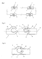
- a multi-part consisting of moldings flat gasket shows in partial view Fig. 1 , Of the unspecified molded parts only each connector 1 forming molding ends 3, 7 are shown.
- a first embodiment of such a connector shows Fig. 2 in a separate state of the connector 1.
- a tongue-shaped projection 2 is formed, which has the shape of a circular ring.
- the arrangement of the tongue-shaped projection 2 is asymmetrical to the central axis 13 of the connector in the FIG. 1 shifted upward, so that in the lower area sufficient space for a second recess 8 remains, which is bounded on the one hand by the tongue-shaped projection 2 and on the other hand by a system 14.
- an insertion opening 9 through which a fastening screw (not shown) can be pushed, by means of which the space to be sealed bounding components (not shown) can be fastened together.
- Forming end 7 shown on the left is widened asymmetrically with respect to the actual sealing strip 15 and provided with a first mouth-shaped recess 6, which is arranged approximately centrally for widening, and which is delimited by two legs 4, 5.
- the inner contour of the first recess 6 corresponds to the outer contour of the tongue-shaped projection 2, while the outer contour of the in the FIG. 2 shown below leg 5 with the inner contour of the second recess 8 in the one mold part end 3, where the tongue-shaped projection 2 is located, corresponds.
- FIG. 3 The Indian FIG. 2 indicated by a dashed line assembly of the connector 1 is in FIG. 3 shown.
- the leg 5 is fixed by the system 14 relative to the tongue-shaped projection 2, so that the leg 5 can not escape.
- the molding ends 3, 7 made with small turbobergerschneidungen results along the dividing line between the tongue-shaped projection 2 and the leg or between this and the system 14, a relatively high surface pressure and thus a high sealing effect, because these areas of the connector relative to each other can not avoid.
- FIG. 2 is in the arrangement after FIG. 3 an insertion opening is not provided, even without this additional measure can achieve a sufficient sealing effect.
- the one mold part end 3 ' also has a tongue-shaped projection 2', the outer contour is designed but polygonal.
- the recess provided in the other molding end 7' is also polygonal in shape, so that, on the one hand, a "toothing" of the two mold part ends 3 ', 7' results and, on the other hand, the two mold part ends 3 ', 7' are defined by the undercuts 11 ', 12' to each other.
- a circular thickening 16 is formed on the leg 5, which is arranged at the bottom in the representation, at its end, which in turn interacts with the corresponding recess defined by the tongue-shaped projection 2 'and the installation 14' in the first molding end 3 ' in that an additional fixing of the leg 5 in the first molded part 3 'is achieved by the undercut 10 thus formed.
- the insertion opening 9 'for a fastening screw provided in the tongue-shaped projection 2' improves the sealing effect already in connection with FIG. 2 described manner, it is made to the statements there.
Landscapes
- Engineering & Computer Science (AREA)
- General Engineering & Computer Science (AREA)
- Mechanical Engineering (AREA)
- Gasket Seals (AREA)
Applications Claiming Priority (1)
| Application Number | Priority Date | Filing Date | Title |
|---|---|---|---|
| DE200710009807 DE102007009807A1 (de) | 2007-02-28 | 2007-02-28 | Mehrteilige Flachdichtung |
Publications (1)
| Publication Number | Publication Date |
|---|---|
| EP1965106A1 true EP1965106A1 (fr) | 2008-09-03 |
Family
ID=39462037
Family Applications (1)
| Application Number | Title | Priority Date | Filing Date |
|---|---|---|---|
| EP08000620A Withdrawn EP1965106A1 (fr) | 2007-02-28 | 2008-01-15 | Joint plat segmenté |
Country Status (2)
| Country | Link |
|---|---|
| EP (1) | EP1965106A1 (fr) |
| DE (2) | DE102007009807A1 (fr) |
Families Citing this family (1)
| Publication number | Priority date | Publication date | Assignee | Title |
|---|---|---|---|---|
| CN109139908A (zh) * | 2017-06-16 | 2019-01-04 | 博西华电器(江苏)有限公司 | 适于家用电器的密封组件和具有该密封组件的家用电器 |
Citations (7)
| Publication number | Priority date | Publication date | Assignee | Title |
|---|---|---|---|---|
| DE8716939U1 (de) | 1987-12-24 | 1988-02-11 | Reinz-Dichtungs-Gmbh, 89233 Neu-Ulm | Flachdichtung |
| DE9106710U1 (de) | 1991-05-31 | 1991-11-21 | Eilenburger Chemie-Werk GmbH, O-7280 Eilenburg | Mehrteilige Flachdichtung |
| US5149108A (en) * | 1991-02-15 | 1992-09-22 | Great Gasket Concepts, Inc. | Multi-piece gasket joint |
| US5161808A (en) * | 1991-02-12 | 1992-11-10 | Great Gasket Concepts, Inc. | Collapsible sealing gasket |
| EP0514052A1 (fr) * | 1991-05-17 | 1992-11-19 | Tokyo Gasket Co., Ltd. | Plaque d'étanchéité divisée |
| DE19630152C1 (de) * | 1996-07-25 | 1997-05-15 | Gloeckler Dichtsysteme Guenter | Formschlüssige Verbindung |
| WO2001044699A1 (fr) * | 1999-12-17 | 2001-06-21 | Parker-Hannifin Corporation | Procede de fabrication d'un joint segmente dote d'un element d'etancheite continu |
-
2007
- 2007-02-28 DE DE200710009807 patent/DE102007009807A1/de not_active Withdrawn
- 2007-02-28 DE DE202007018532U patent/DE202007018532U1/de not_active Expired - Lifetime
-
2008
- 2008-01-15 EP EP08000620A patent/EP1965106A1/fr not_active Withdrawn
Patent Citations (7)
| Publication number | Priority date | Publication date | Assignee | Title |
|---|---|---|---|---|
| DE8716939U1 (de) | 1987-12-24 | 1988-02-11 | Reinz-Dichtungs-Gmbh, 89233 Neu-Ulm | Flachdichtung |
| US5161808A (en) * | 1991-02-12 | 1992-11-10 | Great Gasket Concepts, Inc. | Collapsible sealing gasket |
| US5149108A (en) * | 1991-02-15 | 1992-09-22 | Great Gasket Concepts, Inc. | Multi-piece gasket joint |
| EP0514052A1 (fr) * | 1991-05-17 | 1992-11-19 | Tokyo Gasket Co., Ltd. | Plaque d'étanchéité divisée |
| DE9106710U1 (de) | 1991-05-31 | 1991-11-21 | Eilenburger Chemie-Werk GmbH, O-7280 Eilenburg | Mehrteilige Flachdichtung |
| DE19630152C1 (de) * | 1996-07-25 | 1997-05-15 | Gloeckler Dichtsysteme Guenter | Formschlüssige Verbindung |
| WO2001044699A1 (fr) * | 1999-12-17 | 2001-06-21 | Parker-Hannifin Corporation | Procede de fabrication d'un joint segmente dote d'un element d'etancheite continu |
Also Published As
| Publication number | Publication date |
|---|---|
| DE102007009807A1 (de) | 2008-09-04 |
| DE202007018532U1 (de) | 2008-10-23 |
Similar Documents
| Publication | Publication Date | Title |
|---|---|---|
| EP2962366B1 (fr) | Connecteur électrique industriel | |
| DE102008049052A1 (de) | Filterband | |
| EP2724065B1 (fr) | Raccord de tuyau flexible et système de tuyau flexible correspondant | |
| DE202011101112U1 (de) | Befestigungsvorrichtung | |
| DE2549387A1 (de) | Hochdruck-rohrverbindung | |
| DE102011051291A1 (de) | Steckverbinder mit Kammerblock und Kontaktsicherung | |
| EP2712413B1 (fr) | Dispositif de raccordement permettant de raccorder une conduite de fluides | |
| EP1781979A1 (fr) | Raccord emboitable pour conduites fluidiques | |
| EP2748492B1 (fr) | Liaison pour tige de piston | |
| AT505646B1 (de) | Rohrverbindung mit einem gehäuse einer armatur | |
| EP2845459A1 (fr) | Convoyeur crible pour machines de récolte de fruits hachés | |
| DE102012102545B4 (de) | Kupplungseinrichtung zum Verbinden zweier Frischluftrohre für eine Heizungsanlage | |
| EP2927541A1 (fr) | Élément d'étanchéité et construction d'un joint de conduite | |
| EP3561346B1 (fr) | Joint d'étanchéité, dispositif d'étanchéité et soupape à voies multiples | |
| EP2975311B1 (fr) | Raccord a vis pour tuyaux souples | |
| DE3933667C1 (en) | Combined radial and axial bearing bush - includes split bearing shells and two detachable thrust ring couplings | |
| EP1965106A1 (fr) | Joint plat segmenté | |
| EP2441998B1 (fr) | Elément flexible pour un canal d'écoulement de gaz | |
| DE102008061462B4 (de) | Kühlsystem für einen Verbrennungsmotor | |
| EP4449013A1 (fr) | Luminaire allongé doté d'un capuchon d'extrémité et d'une fonction d'étanchéité | |
| DE102006045325B4 (de) | Zählergehäuse | |
| EP3022807B1 (fr) | Dispositif de verrouillage de connecteurs enfichables | |
| DE102019213028B4 (de) | Dichtungsanordnung mit einer Stützwand | |
| EP3135917B1 (fr) | Pompe à vide | |
| EP2650576A2 (fr) | Raccord double pour la pose étanche de pièces longilignes |
Legal Events
| Date | Code | Title | Description |
|---|---|---|---|
| PUAI | Public reference made under article 153(3) epc to a published international application that has entered the european phase |
Free format text: ORIGINAL CODE: 0009012 |
|
| AK | Designated contracting states |
Kind code of ref document: A1 Designated state(s): AT BE BG CH CY CZ DE DK EE ES FI FR GB GR HR HU IE IS IT LI LT LU LV MC MT NL NO PL PT RO SE SI SK TR |
|
| AX | Request for extension of the european patent |
Extension state: AL BA MK RS |
|
| 17P | Request for examination filed |
Effective date: 20090303 |
|
| 17Q | First examination report despatched |
Effective date: 20090403 |
|
| AKX | Designation fees paid |
Designated state(s): DE FR IT NL SE |
|
| STAA | Information on the status of an ep patent application or granted ep patent |
Free format text: STATUS: THE APPLICATION IS DEEMED TO BE WITHDRAWN |
|
| 18D | Application deemed to be withdrawn |
Effective date: 20090814 |