EP1965174B1 - Écran d'affichage sensible aux stimuli doté de fonctions de contrôle consolidées - Google Patents
Écran d'affichage sensible aux stimuli doté de fonctions de contrôle consolidées Download PDFInfo
- Publication number
- EP1965174B1 EP1965174B1 EP08102092.7A EP08102092A EP1965174B1 EP 1965174 B1 EP1965174 B1 EP 1965174B1 EP 08102092 A EP08102092 A EP 08102092A EP 1965174 B1 EP1965174 B1 EP 1965174B1
- Authority
- EP
- European Patent Office
- Prior art keywords
- display screen
- stimuli
- sensitive display
- areas
- cursor
- Prior art date
- Legal status (The legal status is an assumption and is not a legal conclusion. Google has not performed a legal analysis and makes no representation as to the accuracy of the status listed.)
- Active
Links
Images


Classifications
-
- G—PHYSICS
- G01—MEASURING; TESTING
- G01C—MEASURING DISTANCES, LEVELS OR BEARINGS; SURVEYING; NAVIGATION; GYROSCOPIC INSTRUMENTS; PHOTOGRAMMETRY OR VIDEOGRAMMETRY
- G01C23/00—Combined instruments indicating more than one navigational value, e.g. for aircraft; Combined measuring devices for measuring two or more variables of movement, e.g. distance, speed or acceleration
-
- G—PHYSICS
- G06—COMPUTING OR CALCULATING; COUNTING
- G06F—ELECTRIC DIGITAL DATA PROCESSING
- G06F3/00—Input arrangements for transferring data to be processed into a form capable of being handled by the computer; Output arrangements for transferring data from processing unit to output unit, e.g. interface arrangements
- G06F3/01—Input arrangements or combined input and output arrangements for interaction between user and computer
- G06F3/048—Interaction techniques based on graphical user interfaces [GUI]
- G06F3/0481—Interaction techniques based on graphical user interfaces [GUI] based on specific properties of the displayed interaction object or a metaphor-based environment, e.g. interaction with desktop elements like windows or icons, or assisted by a cursor's changing behaviour or appearance
-
- G—PHYSICS
- G06—COMPUTING OR CALCULATING; COUNTING
- G06F—ELECTRIC DIGITAL DATA PROCESSING
- G06F3/00—Input arrangements for transferring data to be processed into a form capable of being handled by the computer; Output arrangements for transferring data from processing unit to output unit, e.g. interface arrangements
- G06F3/01—Input arrangements or combined input and output arrangements for interaction between user and computer
- G06F3/048—Interaction techniques based on graphical user interfaces [GUI]
- G06F3/0487—Interaction techniques based on graphical user interfaces [GUI] using specific features provided by the input device, e.g. functions controlled by the rotation of a mouse with dual sensing arrangements, or of the nature of the input device, e.g. tap gestures based on pressure sensed by a digitiser
- G06F3/0488—Interaction techniques based on graphical user interfaces [GUI] using specific features provided by the input device, e.g. functions controlled by the rotation of a mouse with dual sensing arrangements, or of the nature of the input device, e.g. tap gestures based on pressure sensed by a digitiser using a touch-screen or digitiser, e.g. input of commands through traced gestures
-
- G—PHYSICS
- G06—COMPUTING OR CALCULATING; COUNTING
- G06F—ELECTRIC DIGITAL DATA PROCESSING
- G06F2203/00—Indexing scheme relating to G06F3/00 - G06F3/048
- G06F2203/048—Indexing scheme relating to G06F3/048
- G06F2203/04803—Split screen, i.e. subdividing the display area or the window area into separate subareas
Definitions
- This disclosure relates generally to display screens, and more particularly to a stimulisensitive display screen with consolidated control functions.
- Flight control system design continues to evolve towards the socalled "glass cockpit” model, where control functions for the aircraft and aircraft subsystems are increasingly displayed and manipulated using MultiFunction Displays (MFDs).
- MFDs MultiFunction Displays
- Example embodiments address these concerns and may also address other unspecified concerns that are nevertheless present in the related art.
- US 6784869 describes a cursor control display having a pair of cursor control devices each having a group of display selector switches. The switches are used to select the CCD cursor to specific displays for use from each CCD.
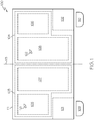
- FIG. 1 is a front aspect diagram illustrating some components of an MFD 100 and a possible display layout on the MFD according to an example embodiment.
- FIG. 1 is from the perspective of a pilot seated facing the front of the MFD 100.
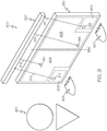
- FIG. 2 is sectional diagram further illustrating the relationship of the components shown in FIG. 1 .
- FIG. 2 is a cross-section along a plane that is parallel to the line 113 of FIG. 1 .
- the MFD 100 includes a stimuli-sensitive display screen 111, a first handrest 109, and a second handrest 110.
- other cockpit structures such as the pilot's seat and bulkheads, which support the handrests 109, 110 and the stimuli-sensitive display screen 111, are not shown.
- a relative position of a pilot 200 is facing the stimuli-sensitive display screen 111.
- the pilot's seat may be manipulated so that the pilot is seated at a desired distance from the sensitive display 111 and the handrest 110.
- the pilot 200 may comfortably place the palm of her hand on top of the handrest 110.
- the handrest 110 is close enough to the screen such that a finger of the hand that is resting on the handrest can be manipulated to contact the stimuli-sensitive display screen 111.
- the location of the handrest 110 relative to the stimuli-sensitive display screen 111 may be adjusted so that a comfortable position may be found for people having different sized hands and fingers.
- An angle 210 exists between the handrest 110 and the stimuli-sensitive display screen 111.
- the exact value of the angle 210 depends upon the structures used to support the handrest 210 and the stimuli-sensitive display screen 111. According to some embodiments, the value of the angle 210 may range from about 90 degrees to about 180 degrees. Since a more obtuse angle is generally more ergonomically comfortable than a less obtuse angle, in presently preferred embodiments the angle 210 is greater than about 135 degrees, and more preferably, the angle is about 180 degrees.
- a stimuli-sensitive display screen is defined as a display screen that is capable of outputting visual data and capable of generating a signal in response to a physical manipulation of the display screen or the environment surrounding the display screen.
- a stimuli-sensitive display screen may be a touch-sensitive display screen that generates a signal in response to a physical touching of a region of the display screen, a proximity-sensitive display screen that generates a signal in response to an object in proximity to a region of the display screen, or a light-sensitive display screen that generates a signal in response to optical radiation striking a region of the display screen.
- the stimuli-sensitive display screen 111 may itself be part of a number of different display devices that generate visual output on the stimuli-sensitive display screen using one of many different technologies.
- the stimuli-sensitive display screen 111 may be part of a color Cathode Ray Tube (CRT) display device, a monochromatic CRT display device, a flat panel display device, a Liquid Crystal Display (LCD) device, a plasma display device, an electro-luminescent display device, a Light Emitting Diode (LED) display device or the like.
- CTR Color Cathode Ray Tube
- LCD Liquid Crystal Display
- LED Light Emitting Diode
- the stimuli-sensitive display screen 111 has a number of regions or areas that are indicated by dashed or dotted lines.
- the shape of the stimuli-sensitive display screen 111 is symmetric about an axis 113 that bisects the stimuli-sensitive display screen into a left region on the left-hand side of the axis 113 and a right region on the right-hand side of the axis 113.
- the areas 101, 103, 105, 107 are symmetric with the areas 102, 104, 106, and 108, respectively.
- the areas 103 and 104 are areas of the stimuli-sensitive display screen 111 that are designated for displaying one or more avionics displays.
- an avionics display is any arrangement of visual data that is used for control, monitoring, or data entry for an aircraft or an aircraft subsystem.
- an avionics display may be one that shows the primary flight displays such as altimeter and heading, or an avionics display may be one that indicates the fuel status of the aircraft or cabin pressure within the aircraft.
- Another avionics display may include both the primary flight displays and the fuel status of the aircraft.
- Another avionics display may include navigation (NAV) or communication (COM) functions, such as radio tuning and control.
- the areas 103 and 104 are also areas of the stimuli-sensitive display screen 111 that are operable to display the cursors 121, 122 respectively.
- the cursors 121, 122 are illustrated as arrows, but the shape of the cursor is not particularly important - many alternative shapes are possible.
- the cursors 121, 122 may be used to select a particular sub-area within the areas 103 and 104. In other words, the cursors can be used to identify a particular portion of an avionics display as the active part of the display. Alternatively, the cursors 121, 122 may be used to select different options in an avionics display that present one or more menu choices or selections for the pilot.
- the cursors 121, 122 may also be used for data entry purposes.
- the cursors 121, 122 may be used to select one virtual keypad from a number of virtual keypads that are generated as part of an avionics display. Each of the keypads may have a unique letter or number associated with it.
- the areas 101 and 102 are areas of the stimuli-sensitive display screen that can be designated for use as Cursor Control Devices (CCDs). That is, inputs detected in the areas 101, 102 are used to control the movement of the cursors 121, 122 that are displayed in the areas 103, 104. In alternative embodiments, the inputs detected in the areas 101, 102 may be used to control the movement of other cursors in other display areas of the display screen 111.
- CCDs Cursor Control Devices
- the inputs detected in the areas 101, 102 may be used to control the movement of other cursors displayed on a second MFD that is different than MFD 100.
- the second MFD includes a stimuli-sensitive display screen.
- the second MFD does not include a stimuli-sensitive display screen.
- inputs detected in area 101 are used to control the movement of the cursor 121 in the area 103, while inputs detected in area 102 are used to control the movement of the cursor 122 in the area 104.
- the cursor 121 is prevented from being displayed in the region to the right of the axis 113, while the cursor 122 is prevented from being displayed in the region to the left of the axis 113.
- the areas 101 and 102 are square areas having sides of approximately two and a half (2.5) inches. This size seems to be convenient, although of course the areas 101 and 102 could have other shapes and sizes.
- a stimuli-sensitive display screen 111 illustrated in FIG. 1 is just one example.
- a stimuli-sensitive display screen may conveniently display a number of different avionics displays in different areas of the display screen. The number is limited only by the maximum size of the display screen and the smallest practically viewable area for each avionics display.
- the areas for the avionics display may be of different sizes, different shapes, and unlike the embodiment illustrated in FIG. 1 , may not be symmetric relative to other display areas.
- the at least one area designated for use as a CCD for a cursor can be dynamically reconfigured in different areas of the stimuli-sensitive display screen according to the wishes of the user of the stimuli-sensitive display screen. That is, different areas of the stimuli-sensitive display screen may be designated for use as the CCD according to the wishes of the user of the stimuli-sensitive display screen. Alternatively, in some situations it may be desirable to not use any portion of the stimuli-sensitive display screen for a CCD. Embodiments are reconfigurable for all situations.
- the MFD 100 is particularly well-suited for cockpit configurations where a pilot and co-pilot are seated side by side.
- other embodiments are not so limited.
- it is common in specialized test aircraft or aboard large military aircraft for one or more crewmembers located in positions other than the pilot position(s) to monitor or control an aircraft subsystem for purposes of redundancy or independence.
- there may be more or less than the two areas 103, 104 for avionics displays and the two areas 101 or 102 for CCDs, depending on the particular crewstation configuration.
- the MFD 100 further includes handrests 109 and 110, which are adapted to work cooperatively with the CCD areas 101, 102, respectively.
- the handrests 109 and 110 are disposed adjacent to their corresponding CCD areas 101, 102, such that a pilot seated in the left position could place the palm of his right hand on the top of the handrest 109 and use a finger to apply inputs to the CCD area 101 of the stimuli-sensitive display screen 111, while another pilot seated in the right position could place the palm of his left hand on the top of the handrest 110 and use a finger to apply inputs to the CCD area 102 of the stimuli-sensitive display screen 111.
- the two pilots can control their corresponding cursors 121 or 122 and manipulate their corresponding avionics displays in areas 103 and 104 in any manner that is desired. It should be apparent that the avionics displays that are present in area 103 need not be the same avionics displays that are present in area 104.
- FIGS. 3, 4, and 5 are top, side, and rear perspective diagrams, respectively, that illustrate an example handrest 300 according to an embodiment.
- the handrest 300 is suitable for use as the handrest 109 or 110 in FIGS. 1 and 2 .
- the handrest 300 has an ergonomic shape.
- the handrest 300 further includes buttons 302, 304, and 306.
- the buttons 302, 304, 306 may be used cooperatively with the cursors 121 or 122 to select or deselect areas of the avionics displays, or choose menu-driven choices that are presented to the pilot in the avionics displays, similar to the way a mouse peripheral and a cursor displayed on a personal computer display screen are used to select, deselect, or choose menu-driven choices.
- the handrest 300 may include large push-buttons that are may be manipulated using a thumb.
- the handrest may include a trackball that is also operable to control a cursor, which could provide a backup in case the CCD areas 101 or 102 experienced a failure.
- the area 103 includes the area 105 and 107, while the area 104 includes the area 106 and 108.
- the areas 105 and 106 are areas of the stimuli-sensitive display screen 111 can be designated for displaying a virtual touchkey array.
- virtual touchkeys can be used, in conjunction with the cursors 121, 122, for data entry.
- the touchkeys themselves may be physically contacted to input data. According to an example embodiment, both methods would be available to a pilot.
- the areas 107 and 108 are areas of the stimuli-sensitive display screen 111 that are designated to display any avionics display other than the array of virtual touchkeys that are displayed in areas 105 and 106.
- FIGS. 6 and 7 illustrate avionics displays 600, 700 according to an example embodiment.
- the avionics displays 600, 700 are just two examples of what can be displayed in areas 107 and 108 of FIG. 1 .
- Avionics display 600 is a compass that illustrates the heading of the aircraft.
- Avionics display 700 is an altimeter that shows the aircraft's elevation above mean sea level. Thus, as was explained above, the avionics displays 600 and 700 would be considered primary flight displays.
- the avionics displays 600 and 700 even though they are generated on a stimuli-sensitive display screen 111, have an appearance that emulates the old-style altimeters and compasses that were implemented with dedicated hardware.
- altimeters or compasses may be implemented in many different ways.
- an altimeter or compass could be simply implemented in a flight data display as a number whose value reflected the aircraft's current altitude and heading.
- FIG. 8 illustrates a virtual touchkey array 800 according to an example embodiment.
- the virtual touchkey array 800 includes a number of pushbuttons 810 that are displayed by the stimuli-sensitive display screen 111.
- Each one of the pushbuttons 810 can be configured to trigger a particular function when the area of the stimuli-sensitive display screen 111 corresponding to the pushbutton 810 is selected using either the cursors 121, 122 and one of the buttons 302, 304, 306 or, alternatively, a direct physical touch to the pushbutton 810.
- the stimuli-sensitive display screen 111 is operable to display any combination of letters, words, numbers, or symbols within the pushbuttons 810 that would indicate the function corresponding to a selection of that particular pushbutton.
- the stimuli-sensitive display screen 111 may display the numbers 0, 1, 2, ..., 8, 9 within a corresponding one of the pushbuttons 810.
- These pushbuttons 810 may be used for data entry.
- letter sequences such as NAV, COM, FUEL, etc., may be displayed.
- These pushbuttons may be used to cause the stimuli-sensitive display screen 111 to display avionics displays associated with NAV, COM, or FUEL functions.
- the pushbuttons 810 are not shown with any particular combination of letter, words, numbers, or symbols to emphasize that the stimuli-sensitive display screen 111 may display any desired combination of letters, words, numbers, or symbols within a pushbutton 810.
- the touchkey array 800 is just one example of a configuration of touchkeys that can be generated in areas 105 and 106 of FIG. 1 . As was explained above, the touchkey array 800 may be used for data entry. According to some embodiments, the selection of a particular pushbutton 810 may result in the display of a different avionics display in the areas 107 and 108.
- FIG. 9 is a block diagram that is representative of some components of a flight control system 900 according to an example embodiment.
- the flight control system 900 includes a stimuli-sensitive display screen 910, a processor 920, and two handrests 906, 907 that are disposed adjacent to the areas 902, 903 of the stimuli-sensitive display screen.
- the stimuli-sensitive display screen 910 and handrests 906, 907 are the same as the stimuli-sensitive display screen 111 and handrests 109, 110 of FIG. 1 , and have the same capabilities. Thus, a duplicative description is omitted.
- the processor 920 is operable to control the stimuli-sensitive display screen 910 in order to generate one or more avionics displays in the areas 904, 905 as well as generate the cursors 914, 915 in the areas 904, 905, respectively.
- the processor 920 preferably encompasses one or more functional blocks and can include any number of individual microprocessors, memories, storage devices, interface cards, or other processor components.
- the areas 902, 903 of the stimuli-sensitive display screen 910 are operable to generate signals 916, 917 when an input is sensed at locations 912, 913 in the areas 902, 903.
- these inputs are caused by a crewmember 901 (e.g., a pilot or co-pilot) who is attempting to control either the cursor 914 or the cursor 915.
- the signals 916, 917 are transmitted to the processor 920.
- the processor 920 generates one or more control signals 917, 918 based upon the signals 916, 917 and these control signals are used to cause different portions of the areas 904, 905 to display the cursors 914, 915.
- a crewmember 901 can control a movement of the cursor 914 or a movement of the cursor 915 based upon a physical manipulation (e.g., a touch) of the cursor control areas 902, 903 of the stimuli-sensitive display screen 910.
- the crewmember 901 can also control the movement of the cursor 914 or a movement of the cursor 915 based upon a physical manipulation (e.g., a touch) of the stimuli-sensitive display screen 910 in the area where the crewmember wishes to place the cursor.
- a physical manipulation e.g., a touch
- the crewmember 901 can also control the movement of the cursor 914 or a movement of the cursor 915 based upon a physical manipulation (e.g., a touch) of the stimuli-sensitive display screen 910 in the area where the crewmember wishes to place the cursor.
- a physical manipulation e.g., a touch
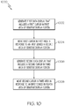
- FIG. 10 is a flow diagram illustrating some example processes that are included in a method 1000 according to an example embodiment.
- the method begins in process 1002 and proceeds sequentially through processes 1004, then 1006, and finally 1008.
- processes 1002 and 1006 may occur concurrently, while in other embodiments processes 1004 and 1008 may occur concurrently.
- Other embodiments may only include a subset of the processes that are included in method 1000.
- Example embodiment 1000 begins with process 1002, which includes generating a first avionics display in a first area of a stimuli-sensitive display screen, where the first avionics display includes a first cursor.
- process 1004 includes moving the first cursor in the first area in response to an input that is sensed in a second area of the stimuli-sensitive display screen.
- the first area of the stimuli-sensitive display screen may be separate from the second area of the stimuli-sensitive display screen.
- the first avionics display may be generated on a display screen that is different from the stimuli-sensitive display screen.
- process 1006 includes generating a second data display in a third area of the stimuli-sensitive display screen, where the second data display includes a second cursor.
- process 1008 includes moving the second cursor in the third area in response to an input that is sensed in a fourth area of the stimuli-sensitive display screen.
Landscapes
- Engineering & Computer Science (AREA)
- General Engineering & Computer Science (AREA)
- Theoretical Computer Science (AREA)
- Physics & Mathematics (AREA)
- General Physics & Mathematics (AREA)
- Human Computer Interaction (AREA)
- Radar, Positioning & Navigation (AREA)
- Remote Sensing (AREA)
- Aviation & Aerospace Engineering (AREA)
- User Interface Of Digital Computer (AREA)
- Controls And Circuits For Display Device (AREA)
Claims (2)
- Appareil comprenant un écran d'affichage sensible aux stimuli (SSD) ayant :une forme symétrique par rapport à un axe (113) qui divise l'écran en une région de gauche sur le côté gauche de l'axe (113) et en une région de droite sur le côté droit de l'axe (113),une première zone (101) dans la région de gauche du SSD, désignée pour être utilisée comme premier dispositif de commande à curseur, et une deuxième zone (102) dans la région de droite du SSD, désignée pour être utilisée comme second dispositif de commande de curseur, dans lequel le premier dispositif de commande de curseur peut fonctionner pour générer un premier signal pour la commande d'un premier curseur (121) dans une troisième zone (103) dans la région de gauche du SSD en réponse à la détection d'une première entrée par le premier dispositif de commande de curseur, tandis que le second dispositif de commande de curseur peut fonctionner pour générer un second signal pour la commande d'un second curseur (122) dans une quatrième zone (104) dans la région de droite du SSD, en réponse à la détection d'une seconde entrée par le second dispositif de commande de curseur,dans lequel les troisième et quatrième zones (103, 104) sont désignées pour l'affichage de données visuelles etdans lequel le premier curseur (121) est désactivé de l'affichage dans la région de droite du SSD et le second curseur (122) est désactivé de l'affichage dans la région de gauche du SSD.
- Appareil selon la revendication 1, comportant en outre :un premier repose-main (109), disposé à côté de la première zone (101) du SSD ; etun second repose-main (110), disposé à côté de la deuxième zone (102) du SSD, de sorte qu'un pilote puisse placer une paume sur le premier ou sur le second repose-main et utiliser un doigt pour appliquer des entrées à la première ou à la deuxième zone, respectivement.
Applications Claiming Priority (1)
| Application Number | Priority Date | Filing Date | Title |
|---|---|---|---|
| US11/680,418 US20080204419A1 (en) | 2007-02-28 | 2007-02-28 | Stimuli-sensitive display screen with consolidated control functions |
Publications (3)
| Publication Number | Publication Date |
|---|---|
| EP1965174A2 EP1965174A2 (fr) | 2008-09-03 |
| EP1965174A3 EP1965174A3 (fr) | 2013-12-18 |
| EP1965174B1 true EP1965174B1 (fr) | 2020-05-27 |
Family
ID=39512694
Family Applications (1)
| Application Number | Title | Priority Date | Filing Date |
|---|---|---|---|
| EP08102092.7A Active EP1965174B1 (fr) | 2007-02-28 | 2008-02-27 | Écran d'affichage sensible aux stimuli doté de fonctions de contrôle consolidées |
Country Status (2)
| Country | Link |
|---|---|
| US (1) | US20080204419A1 (fr) |
| EP (1) | EP1965174B1 (fr) |
Families Citing this family (11)
| Publication number | Priority date | Publication date | Assignee | Title |
|---|---|---|---|---|
| US8681109B2 (en) * | 2007-02-28 | 2014-03-25 | Honeywell International Inc. | Display system and method including a stimuli-sensitive multi-function display with consolidated control functions |
| JP5536729B2 (ja) * | 2011-09-20 | 2014-07-02 | 株式会社ソニー・コンピュータエンタテインメント | 情報処理装置、アプリケーション提供システム、アプリケーション提供サーバ、アプリケーション提供方法、および情報処理方法 |
| CN103513908B (zh) * | 2012-06-29 | 2017-03-29 | 国际商业机器公司 | 用于在触摸屏上控制光标的方法和装置 |
| US8779946B1 (en) * | 2012-08-29 | 2014-07-15 | Rockwell Collins, Inc. | Emulation of aircraft advisory panels |
| FR3001813B1 (fr) * | 2013-02-07 | 2015-03-06 | Thales Sa | Dispositif de visualisation et de controle pour cockpit d'aeronef, systeme de pilotage et aeronef associes |
| KR101739791B1 (ko) * | 2015-05-11 | 2017-05-26 | 주식회사 하이딥 | 압력 센싱 장치, 압력 검출기 및 이들을 포함하는 장치 |
| US10656767B2 (en) | 2015-10-06 | 2020-05-19 | American Panel Corporation | Redundant projected capacitive touch panel |
| EP3360030B1 (fr) * | 2015-10-06 | 2021-11-17 | American Panel Corporation | Panneau tactile redondant |
| US10558314B2 (en) | 2015-10-06 | 2020-02-11 | American Panel Corporation | Redundant resistive touch panel |
| CN107608815B (zh) * | 2017-09-18 | 2021-01-01 | 中国航空工业集团公司洛阳电光设备研究所 | 用于机载显示系统的多通道显示处理及完整性循环监控装置和方法 |
| CN113141433B (zh) * | 2021-03-23 | 2022-10-28 | 网易(杭州)网络有限公司 | 测试屏幕灵敏度的方法、装置和处理器 |
Family Cites Families (11)
| Publication number | Priority date | Publication date | Assignee | Title |
|---|---|---|---|---|
| FR2689290B1 (fr) * | 1992-03-26 | 1994-06-10 | Aerospatiale | Procede et dispositif de communication multimodes et multifonctions entre un operateur et un ou plusieurs processeurs. |
| FR2702576B1 (fr) * | 1993-03-12 | 1995-06-09 | Sextant Avionique | Terminal pour un dialogue homme/machine avec un système informatique faisant intervenir une pluralité d'éléments de visualisation. |
| DE4446139C2 (de) * | 1993-12-30 | 2000-08-17 | Intel Corp | Verfahren und Einrichtung zum Hervorheben von Objekten in einem Konferenzsystem |
| US5825352A (en) * | 1996-01-04 | 1998-10-20 | Logitech, Inc. | Multiple fingers contact sensing method for emulating mouse buttons and mouse operations on a touch sensor pad |
| FR2748145B1 (fr) * | 1996-04-30 | 1998-07-10 | Sextant Avionique | Procede et dispositif d'entree et de controle de donnees de vol |
| US5748185A (en) * | 1996-07-03 | 1998-05-05 | Stratos Product Development Group | Touchpad with scroll and pan regions |
| US6112141A (en) * | 1997-10-15 | 2000-08-29 | Dassault Aviation | Apparatus and method for graphically oriented aircraft display and control |
| US6757002B1 (en) * | 1999-11-04 | 2004-06-29 | Hewlett-Packard Development Company, L.P. | Track pad pointing device with areas of specialized function |
| EP1160160A3 (fr) * | 2000-05-31 | 2002-01-30 | EADS Airbus GmbH | Dispositif pour la commande et la surveillance de systèmes de cabine d'un avion |
| US6784869B1 (en) * | 2000-11-15 | 2004-08-31 | The Boeing Company | Cursor and display management system for multi-function control and display system |
| US7730401B2 (en) * | 2001-05-16 | 2010-06-01 | Synaptics Incorporated | Touch screen with user interface enhancement |
-
2007
- 2007-02-28 US US11/680,418 patent/US20080204419A1/en not_active Abandoned
-
2008
- 2008-02-27 EP EP08102092.7A patent/EP1965174B1/fr active Active
Non-Patent Citations (1)
| Title |
|---|
| None * |
Also Published As
| Publication number | Publication date |
|---|---|
| US20080204419A1 (en) | 2008-08-28 |
| EP1965174A3 (fr) | 2013-12-18 |
| EP1965174A2 (fr) | 2008-09-03 |
Similar Documents
| Publication | Publication Date | Title |
|---|---|---|
| US8681109B2 (en) | Display system and method including a stimuli-sensitive multi-function display with consolidated control functions | |
| EP1965174B1 (fr) | Écran d'affichage sensible aux stimuli doté de fonctions de contrôle consolidées | |
| US20070198141A1 (en) | Cockpit display system | |
| US8390573B2 (en) | Data processing device | |
| US6668215B2 (en) | Aircraft dialog device, through which a dialog with a system of said aircraft is possible | |
| KR101829694B1 (ko) | 적응형 터치 스크린 키패드 상에 디스플레이된 문자를 확대하는 방법 | |
| US6980198B1 (en) | Multifunction keyboard for advanced cursor driven avionic flight decks | |
| EP2698705A2 (fr) | Procédés d'affichage sur une interface d'utilisateur graphique | |
| US8159464B1 (en) | Enhanced flight display with improved touchscreen interface | |
| EP1573487B1 (fr) | Procede et appareil pour faciliter la saisie d'une configuration de donnees reglable manuellement dans le poste de pilotage d'un aeronef | |
| US20140132528A1 (en) | Aircraft haptic touch screen and method for operating same | |
| US20110187651A1 (en) | Touch screen having adaptive input parameter | |
| US7724240B2 (en) | Multifunction keyboard for advanced cursor driven avionic flight decks | |
| JP2013093025A (ja) | 有効なタッチスクリーン入力を判定する方法 | |
| US9128594B1 (en) | Touch interfaces and controls for aviation displays | |
| US10831355B2 (en) | Systems and methods for changing orientation of visual information displayed between adjacent users | |
| CA2824090A1 (fr) | Unites d'entree | |
| US8083186B2 (en) | Input/steering mechanisms and aircraft control systems for use on aircraft | |
| US9084490B2 (en) | Man-machine interface with pointer means and an armrest, and a vehicle | |
| Dodd et al. | Touch on the flight deck: The impact of display location, size, touch technology & turbulence on pilot performance | |
| GB2514640A (en) | Control panel for use in controlling a large area display | |
| Avsar et al. | Target size guidelines for interactive displays on the flight deck | |
| US11008117B1 (en) | Flight deck display station with split keyboard | |
| US20160313961A1 (en) | Method and system for interaction between displays in a cockpit of an aircraft | |
| US20140358334A1 (en) | Aircraft instrument cursor control using multi-touch deep sensors |
Legal Events
| Date | Code | Title | Description |
|---|---|---|---|
| PUAI | Public reference made under article 153(3) epc to a published international application that has entered the european phase |
Free format text: ORIGINAL CODE: 0009012 |
|
| 17P | Request for examination filed |
Effective date: 20080227 |
|
| AK | Designated contracting states |
Kind code of ref document: A2 Designated state(s): AT BE BG CH CY CZ DE DK EE ES FI FR GB GR HR HU IE IS IT LI LT LU LV MC MT NL NO PL PT RO SE SI SK TR |
|
| AX | Request for extension of the european patent |
Extension state: AL BA MK RS |
|
| PUAL | Search report despatched |
Free format text: ORIGINAL CODE: 0009013 |
|
| AK | Designated contracting states |
Kind code of ref document: A3 Designated state(s): AT BE BG CH CY CZ DE DK EE ES FI FR GB GR HR HU IE IS IT LI LT LU LV MC MT NL NO PL PT RO SE SI SK TR |
|
| AX | Request for extension of the european patent |
Extension state: AL BA MK RS |
|
| RIC1 | Information provided on ipc code assigned before grant |
Ipc: G06F 3/041 20060101ALI20131113BHEP Ipc: G01C 23/00 20060101AFI20131113BHEP Ipc: G06F 3/048 20130101ALI20131113BHEP |
|
| 17Q | First examination report despatched |
Effective date: 20140326 |
|
| AKX | Designation fees paid |
Designated state(s): FR |
|
| REG | Reference to a national code |
Ref country code: DE Ref legal event code: R108 |
|
| REG | Reference to a national code |
Ref country code: DE Ref legal event code: R108 Effective date: 20140827 |
|
| RAP1 | Party data changed (applicant data changed or rights of an application transferred) |
Owner name: HONEYWELL INTERNATIONAL INC. |
|
| GRAP | Despatch of communication of intention to grant a patent |
Free format text: ORIGINAL CODE: EPIDOSNIGR1 |
|
| INTG | Intention to grant announced |
Effective date: 20200116 |
|
| GRAS | Grant fee paid |
Free format text: ORIGINAL CODE: EPIDOSNIGR3 |
|
| GRAA | (expected) grant |
Free format text: ORIGINAL CODE: 0009210 |
|
| STAA | Information on the status of an ep patent application or granted ep patent |
Free format text: STATUS: THE PATENT HAS BEEN GRANTED |
|
| AK | Designated contracting states |
Kind code of ref document: B1 Designated state(s): FR |
|
| PLBE | No opposition filed within time limit |
Free format text: ORIGINAL CODE: 0009261 |
|
| STAA | Information on the status of an ep patent application or granted ep patent |
Free format text: STATUS: NO OPPOSITION FILED WITHIN TIME LIMIT |
|
| 26N | No opposition filed |
Effective date: 20210302 |
|
| P01 | Opt-out of the competence of the unified patent court (upc) registered |
Effective date: 20230525 |
|
| PGFP | Annual fee paid to national office [announced via postgrant information from national office to epo] |
Ref country code: FR Payment date: 20260224 Year of fee payment: 19 |