EP1965471A2 - Wasserdichtes Gehäuse für elektrische Geräte - Google Patents
Wasserdichtes Gehäuse für elektrische Geräte Download PDFInfo
- Publication number
- EP1965471A2 EP1965471A2 EP08425133A EP08425133A EP1965471A2 EP 1965471 A2 EP1965471 A2 EP 1965471A2 EP 08425133 A EP08425133 A EP 08425133A EP 08425133 A EP08425133 A EP 08425133A EP 1965471 A2 EP1965471 A2 EP 1965471A2
- Authority
- EP
- European Patent Office
- Prior art keywords
- box
- opening
- cover
- closed
- bolt
- Prior art date
- Legal status (The legal status is an assumption and is not a legal conclusion. Google has not performed a legal analysis and makes no representation as to the accuracy of the status listed.)
- Withdrawn
Links
Images
Classifications
-
- H—ELECTRICITY
- H01—ELECTRIC ELEMENTS
- H01R—ELECTRICALLY-CONDUCTIVE CONNECTIONS; STRUCTURAL ASSOCIATIONS OF A PLURALITY OF MUTUALLY-INSULATED ELECTRICAL CONNECTING ELEMENTS; COUPLING DEVICES; CURRENT COLLECTORS
- H01R13/00—Details of coupling devices of the kinds covered by groups H01R12/70 or H01R24/00 - H01R33/00
- H01R13/46—Bases; Cases
- H01R13/52—Dustproof, splashproof, drip-proof, waterproof, or flameproof cases
-
- H—ELECTRICITY
- H01—ELECTRIC ELEMENTS
- H01R—ELECTRICALLY-CONDUCTIVE CONNECTIONS; STRUCTURAL ASSOCIATIONS OF A PLURALITY OF MUTUALLY-INSULATED ELECTRICAL CONNECTING ELEMENTS; COUPLING DEVICES; CURRENT COLLECTORS
- H01R13/00—Details of coupling devices of the kinds covered by groups H01R12/70 or H01R24/00 - H01R33/00
- H01R13/46—Bases; Cases
- H01R13/502—Bases; Cases composed of different pieces
-
- H—ELECTRICITY
- H01—ELECTRIC ELEMENTS
- H01R—ELECTRICALLY-CONDUCTIVE CONNECTIONS; STRUCTURAL ASSOCIATIONS OF A PLURALITY OF MUTUALLY-INSULATED ELECTRICAL CONNECTING ELEMENTS; COUPLING DEVICES; CURRENT COLLECTORS
- H01R13/00—Details of coupling devices of the kinds covered by groups H01R12/70 or H01R24/00 - H01R33/00
- H01R13/62—Means for facilitating engagement or disengagement of coupling parts or for holding them in engagement
- H01R13/639—Additional means for holding or locking coupling parts together, after engagement, e.g. separate keylock, retainer strap
- H01R13/6397—Additional means for holding or locking coupling parts together, after engagement, e.g. separate keylock, retainer strap with means for preventing unauthorised use
-
- H—ELECTRICITY
- H01—ELECTRIC ELEMENTS
- H01R—ELECTRICALLY-CONDUCTIVE CONNECTIONS; STRUCTURAL ASSOCIATIONS OF A PLURALITY OF MUTUALLY-INSULATED ELECTRICAL CONNECTING ELEMENTS; COUPLING DEVICES; CURRENT COLLECTORS
- H01R13/00—Details of coupling devices of the kinds covered by groups H01R12/70 or H01R24/00 - H01R33/00
- H01R13/66—Structural association with built-in electrical component
- H01R13/70—Structural association with built-in electrical component with built-in switch
- H01R13/701—Structural association with built-in electrical component with built-in switch the switch being actuated by an accessory, e.g. cover, locking member
-
- H—ELECTRICITY
- H02—GENERATION; CONVERSION OR DISTRIBUTION OF ELECTRIC POWER
- H02G—INSTALLATION OF ELECTRIC CABLES OR LINES, OR OF COMBINED OPTICAL AND ELECTRIC CABLES OR LINES
- H02G3/00—Installations of electric cables or lines or protective tubing therefor in or on buildings, equivalent structures or vehicles
- H02G3/02—Details
- H02G3/08—Distribution boxes; Connection or junction boxes
- H02G3/088—Dustproof, splashproof, drip-proof, waterproof, or flameproof casings or inlets
-
- H—ELECTRICITY
- H01—ELECTRIC ELEMENTS
- H01R—ELECTRICALLY-CONDUCTIVE CONNECTIONS; STRUCTURAL ASSOCIATIONS OF A PLURALITY OF MUTUALLY-INSULATED ELECTRICAL CONNECTING ELEMENTS; COUPLING DEVICES; CURRENT COLLECTORS
- H01R13/00—Details of coupling devices of the kinds covered by groups H01R12/70 or H01R24/00 - H01R33/00
- H01R13/46—Bases; Cases
- H01R13/50—Bases; Cases formed as an integral body
- H01R13/501—Bases; Cases formed as an integral body comprising an integral hinge or a frangible part
-
- H—ELECTRICITY
- H01—ELECTRIC ELEMENTS
- H01R—ELECTRICALLY-CONDUCTIVE CONNECTIONS; STRUCTURAL ASSOCIATIONS OF A PLURALITY OF MUTUALLY-INSULATED ELECTRICAL CONNECTING ELEMENTS; COUPLING DEVICES; CURRENT COLLECTORS
- H01R13/00—Details of coupling devices of the kinds covered by groups H01R12/70 or H01R24/00 - H01R33/00
- H01R13/46—Bases; Cases
- H01R13/52—Dustproof, splashproof, drip-proof, waterproof, or flameproof cases
- H01R13/5205—Sealing means between cable and housing, e.g. grommet
-
- H—ELECTRICITY
- H01—ELECTRIC ELEMENTS
- H01R—ELECTRICALLY-CONDUCTIVE CONNECTIONS; STRUCTURAL ASSOCIATIONS OF A PLURALITY OF MUTUALLY-INSULATED ELECTRICAL CONNECTING ELEMENTS; COUPLING DEVICES; CURRENT COLLECTORS
- H01R13/00—Details of coupling devices of the kinds covered by groups H01R12/70 or H01R24/00 - H01R33/00
- H01R13/46—Bases; Cases
- H01R13/52—Dustproof, splashproof, drip-proof, waterproof, or flameproof cases
- H01R13/5213—Covers
-
- H—ELECTRICITY
- H01—ELECTRIC ELEMENTS
- H01R—ELECTRICALLY-CONDUCTIVE CONNECTIONS; STRUCTURAL ASSOCIATIONS OF A PLURALITY OF MUTUALLY-INSULATED ELECTRICAL CONNECTING ELEMENTS; COUPLING DEVICES; CURRENT COLLECTORS
- H01R13/00—Details of coupling devices of the kinds covered by groups H01R12/70 or H01R24/00 - H01R33/00
- H01R13/46—Bases; Cases
- H01R13/52—Dustproof, splashproof, drip-proof, waterproof, or flameproof cases
- H01R13/5216—Dustproof, splashproof, drip-proof, waterproof, or flameproof cases characterised by the sealing material, e.g. gels or resins
Definitions
- This invention concerns the command, control, socket and similar electric devices, and in particular regards a support box for the installation of electric devices, which comprises a base body or container designed to house and enclose at least one electric device and closed at the front by a cover and which, in the case of some external installations must be sealed to protect the devices it houses from atmospheric agents, humidity, dust, etc.
- the cover is hinged to the container or base body; is turning between an open position and a closed position respectively to allow and prevent access to the inside of said body; and it is equipped with means suitable to define and establish its open position, a flexible means supporting its return to the closed position and means of blocking to keep it closed on the front of the base body.
- the blocking means are made up of bolts positioned on opposite sides of the base body, which can be operated like pushbuttons and engage with corresponding recesses provided in the cover.
- the body and the cover have two facing elastomer elements provided to close said opening when there is no cable and to close around the cable when present, to provide a seal at that level as well.
- Such a protective box for electric equipment was however found to be susceptible to implementation in some of its sealing, functional and safety aspects.
- the seal level with the opening for the passage of the cable can cause problems when there is no cable and/or due to some deformations of the elastomer elements.
- One of the objectives of this invention is to provide a remedy for this problem by equipping the protective box with an auxiliary sealing element.
- Another objective of this invention is to provide a protective box for electric devices like the abovementioned one including means for automatically switching off the feed current when the cover is opened and/or on disconnecting the plug that connects up to the socket.
- a further objective of this invention is therefore to provide a protective box for electric devices of the abovementioned type including an additional blocking system in safety, which can only be disconnected on purpose and by using the appropriate key to unlock it.
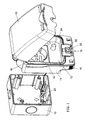
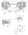
- the box comprises a box shaped body 11 forming a housing 12 closed at the front by a cover 13 with the interposition of a seal 14.
- the body 11 can be fixed to a built-in container 15, or to some other support base, and designed to receive at least an electric device to be protected, represented in the example by an electric socket 16.
- the cover 13 is connected to the body 11 by means of a hinge axis 17 so as to be able to turn between an open position and a closed position of said housing.
- the cover when it is closed, is blocked against the body by stop bolts 18 positioned on the opposite sides of the box shaped body, which can be operated like pushbuttons and engage with corresponding recesses provided in the cover as described in detail in the abovementioned application for utility model of the same applicant.
- the body 11 and the cover 13 define an opening 19 for the passage of a cable, not shown, like the one for a plug to be inserted in the electric socket 16, and in said opening 19 some elastomer sealing elements 19' are provided to close around said cable as soon as the cover is closed.
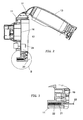
- an additional barrier is provided which is oriented and movable perpendicularly to said opening - Figs 1-3 .
- Said barrier is made up of a retractable closing tang 20 that is guided in a slot 21 provided in the body 11 and stressed by a spring 22. This spring normally maintains the closing tang 20 in an active position during which it protrudes out of the opening 19, completely obstructing it.
- the tang 20 forms a mechanical closure of the opening 19 between body 11 and a cover 13, that adds to the seal offered by the elastomer elements 19' to ensure a tight seal of the opening 19, consequently of the body, even in the absence of a cable and possible deformations of said elements.
- the tang 20 retracts into slot 21 in an inactive position opposing said spring 22 as soon as said opening is crossed by the cable, then leaving the sealing function only to the elastomer elements enclosing the cable.
- a switch 24 is provided that inserted in the power line of the device installed in the protective box through a connection to a terminal board 25 provided in the built-in container 15, that is, to the base support the protective box is attached to.
- the switch 24 can be operated by a member provided inside the cover or by a component of the electric device, in the case of a plug to be connected to the electric socket 16.
- the switch can be of any type and it is preset so as to be normally closed for regular feeding of the electric device 16 when the cover is closed (that is when the socket and plug are connected) and feed to the electric device interrupted as soon as the cover is opened.
- the power, or not, to the electric device can also be shown by means of a luminous warning associated with said switch and possibly visible through a partially transparent cover.
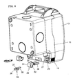
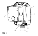
- the protective box is equipped with an additional blocking system 26 of the cover on closing, a system only enabling the intentional and/or authorised opening of the cover with the availability of an appropriate key.
- this system is associated with one or both the stop bolts 18 of the cover of the body.
- Each pushbutton bolt 15 slides between a blocked and a released position in a relative seat 27 provided in the box shaped body 11 and which has a cavity 28 open towards the rear of said body.
- the additional blocking system 26 comprises a first element 29 and a second element 30 designed to engage either with a bolt 15 or with themselves.
- the first element 29 has a head 31 crossed by a hole 32 from which a tooth 33 and two arms 34 like a fork and where an opening 35 is provided basically in the shape of a keyhole between said two arms.
- the second element 30 also has a head 36 crossed by a hole 37 and it extends into a shank 38, basically cylindrical, bearing a radial overhang 39 with a key shaped configuration.
- the first element 29 of the system 26 is used by making the arms 34 fit into the bolt cavity 15 and the tooth 33 in the sliding seat 27 of the bolt, between the latter and the body 11. Then, the shank 38 with overhang 39 of the second element 30 is inserted deeply in the opening 35 between the two arms of the first element 29 and turned at 90° so that the overhang engages on a level with an internal undercut or shoulder 40 provided in the pushbutton bolt 18 (or in the body 11) in the rear of the first element 29 and the holes in the heads of the two elements 29, 30 which are in line.
- the tooth of the first element 29 of the system avoids any possible jerking of the bolt thus preventing the release and opening of the cover 13 and at the same time the second element 30, which engages with the undercut or shoulder 40, prevents the first element 29 from sliding out of the cavity of the bolt.
- a safety lock 41 that is made to engage the coincident holes 32, 37 of the heads of the two elements 29, 30 of the system and which once closed can be opened by an appropriate key, without which the cover of the protective box cannot be opened.
- the box according to this invention can also contain several electric devices positioned side by side, for example a socket, a luminous warning and/or other equipment which require protection of the type described above.
Landscapes
- Engineering & Computer Science (AREA)
- Computer Security & Cryptography (AREA)
- Architecture (AREA)
- Civil Engineering (AREA)
- Structural Engineering (AREA)
- Connection Or Junction Boxes (AREA)
- Patch Boards (AREA)
- Connector Housings Or Holding Contact Members (AREA)
- Switch Cases, Indication, And Locking (AREA)
Applications Claiming Priority (1)
| Application Number | Priority Date | Filing Date | Title |
|---|---|---|---|
| ITBS20070012 ITBS20070012U1 (it) | 2007-03-01 | 2007-03-01 | "scatola a tenuta stagna per dispositivi elettrici" |
Publications (2)
| Publication Number | Publication Date |
|---|---|
| EP1965471A2 true EP1965471A2 (de) | 2008-09-03 |
| EP1965471A3 EP1965471A3 (de) | 2009-10-21 |
Family
ID=39494214
Family Applications (1)
| Application Number | Title | Priority Date | Filing Date |
|---|---|---|---|
| EP08425133A Withdrawn EP1965471A3 (de) | 2007-03-01 | 2008-03-03 | Wasserdichtes Gehäuse für elektrische Geräte |
Country Status (2)
| Country | Link |
|---|---|
| EP (1) | EP1965471A3 (de) |
| IT (1) | ITBS20070012U1 (de) |
Cited By (14)
| Publication number | Priority date | Publication date | Assignee | Title |
|---|---|---|---|---|
| EP2337159A1 (de) * | 2009-12-17 | 2011-06-22 | REV Ritter GmbH | Aufputz-Steckdose und Aufputz-Installationsgeräteserie |
| CN102130394A (zh) * | 2011-01-28 | 2011-07-20 | 纽福克斯光电科技(上海)有限公司 | 一种节电电源插座 |
| EP2448069A1 (de) * | 2010-10-26 | 2012-05-02 | Tyco Electronics AMP España S.A. | Kommunikationsanschluss-Gehäusekasten |
| CN104953347A (zh) * | 2015-07-10 | 2015-09-30 | 常州汇森电子有限公司 | 带折叠帆布盖的网线开关插座 |
| CN105206989A (zh) * | 2015-10-08 | 2015-12-30 | 沈阳兴华航空电器有限责任公司 | 一种防淋雨型充电电源插座 |
| CN105356123A (zh) * | 2015-12-21 | 2016-02-24 | 宁波迪亚家用电器有限公司 | 一种带有滑盖的插座 |
| CN105633677A (zh) * | 2015-12-21 | 2016-06-01 | 宁波迪亚家用电器有限公司 | 一种防尘安全插座 |
| CN105846271A (zh) * | 2016-06-06 | 2016-08-10 | 广西新全通电子技术有限公司 | 一种咬合式的排插 |
| CN105896163A (zh) * | 2016-06-16 | 2016-08-24 | 广西南宁百兰斯科技开发有限公司 | 一种易于固定的防水插排 |
| GB2544068A (en) * | 2015-11-04 | 2017-05-10 | Capuzza Rossano | Improvements for an electrical supply unit |
| WO2018064706A1 (en) * | 2016-10-04 | 2018-04-12 | Ampfibian Holdings Pty Ltd | Outdoor electrical plug and socket cover |
| CN108551017A (zh) * | 2018-04-10 | 2018-09-18 | 浙江海宁和金电子科技有限公司 | 一种适用多环境使用的电器插座 |
| GB2566525A (en) * | 2017-09-18 | 2019-03-20 | Eaton Ind France Sas | Safety device for providing an access to one or more electrical connectors |
| USD897931S1 (en) | 2019-12-19 | 2020-10-06 | Shenzhen Shenyuanxin Technology Co., Ltd. | Automobile charging port cover |
Family Cites Families (6)
| Publication number | Priority date | Publication date | Assignee | Title |
|---|---|---|---|---|
| GB2269485B (en) * | 1992-07-20 | 1996-02-21 | Mk Electric Ltd | Connector assembly |
| GB0002161D0 (en) * | 2000-02-01 | 2000-03-22 | Pressac Communications Limited | Waterproof enclosures |
| JP2001289801A (ja) * | 2000-04-06 | 2001-10-19 | Seiko Instruments Inc | 蛍光x線分析装置 |
| GB0019449D0 (en) * | 2000-08-09 | 2000-09-27 | Connell Michelle C O | Electric socket/plug cover |
| FR2823603B1 (fr) * | 2001-04-17 | 2003-08-15 | Legrand Sa | Appareil electrique etanche |
| US7355130B2 (en) * | 2004-04-09 | 2008-04-08 | Siemens Information And Communication Networks, Inc. | Cable sealing device |
-
2007
- 2007-03-01 IT ITBS20070012 patent/ITBS20070012U1/it unknown
-
2008
- 2008-03-03 EP EP08425133A patent/EP1965471A3/de not_active Withdrawn
Cited By (23)
| Publication number | Priority date | Publication date | Assignee | Title |
|---|---|---|---|---|
| EP2337159A1 (de) * | 2009-12-17 | 2011-06-22 | REV Ritter GmbH | Aufputz-Steckdose und Aufputz-Installationsgeräteserie |
| EP2448069A1 (de) * | 2010-10-26 | 2012-05-02 | Tyco Electronics AMP España S.A. | Kommunikationsanschluss-Gehäusekasten |
| CN102130394A (zh) * | 2011-01-28 | 2011-07-20 | 纽福克斯光电科技(上海)有限公司 | 一种节电电源插座 |
| CN104953347A (zh) * | 2015-07-10 | 2015-09-30 | 常州汇森电子有限公司 | 带折叠帆布盖的网线开关插座 |
| CN105206989A (zh) * | 2015-10-08 | 2015-12-30 | 沈阳兴华航空电器有限责任公司 | 一种防淋雨型充电电源插座 |
| CN105206989B (zh) * | 2015-10-08 | 2017-08-29 | 沈阳兴华航空电器有限责任公司 | 一种防淋雨型充电电源插座 |
| GB2544068A (en) * | 2015-11-04 | 2017-05-10 | Capuzza Rossano | Improvements for an electrical supply unit |
| GB2544068B (en) * | 2015-11-04 | 2021-10-06 | Capuzza Rossano | Improvements for an electrical supply unit |
| CN105356123A (zh) * | 2015-12-21 | 2016-02-24 | 宁波迪亚家用电器有限公司 | 一种带有滑盖的插座 |
| CN105633677B (zh) * | 2015-12-21 | 2017-12-19 | 宁波法米莱美妆工具有限公司 | 一种防尘安全插座 |
| CN105633677A (zh) * | 2015-12-21 | 2016-06-01 | 宁波迪亚家用电器有限公司 | 一种防尘安全插座 |
| CN105846271A (zh) * | 2016-06-06 | 2016-08-10 | 广西新全通电子技术有限公司 | 一种咬合式的排插 |
| CN105896163A (zh) * | 2016-06-16 | 2016-08-24 | 广西南宁百兰斯科技开发有限公司 | 一种易于固定的防水插排 |
| US10923851B2 (en) | 2016-10-04 | 2021-02-16 | Ampfibian Holdings Pty Ltd | Outdoor electrical plug and socket cover |
| GB2569762A (en) * | 2016-10-04 | 2019-06-26 | Ampfibian Holdings Pty Ltd | Outdoor electrical plug and socket cover |
| WO2018064706A1 (en) * | 2016-10-04 | 2018-04-12 | Ampfibian Holdings Pty Ltd | Outdoor electrical plug and socket cover |
| GB2569762B (en) * | 2016-10-04 | 2022-06-08 | Ampfibian Holdings Pty Ltd | Outdoor electrical plug and socket cover |
| AU2017338618B2 (en) * | 2016-10-04 | 2022-12-15 | Ampfibian Holdings Pty Ltd | Outdoor electrical plug and socket cover |
| GB2566525A (en) * | 2017-09-18 | 2019-03-20 | Eaton Ind France Sas | Safety device for providing an access to one or more electrical connectors |
| GB2568152A (en) * | 2017-09-18 | 2019-05-08 | Eaton Ind France Sas | Safety device for providing an access to one or more electrical connectors |
| GB2568152B (en) * | 2017-09-18 | 2022-05-25 | Eaton Ind France Sas | Safety device for providing an access to one or more electrical connectors |
| CN108551017A (zh) * | 2018-04-10 | 2018-09-18 | 浙江海宁和金电子科技有限公司 | 一种适用多环境使用的电器插座 |
| USD897931S1 (en) | 2019-12-19 | 2020-10-06 | Shenzhen Shenyuanxin Technology Co., Ltd. | Automobile charging port cover |
Also Published As
| Publication number | Publication date |
|---|---|
| EP1965471A3 (de) | 2009-10-21 |
| ITBS20070012U1 (it) | 2008-09-02 |
Similar Documents
| Publication | Publication Date | Title |
|---|---|---|
| EP1965471A2 (de) | Wasserdichtes Gehäuse für elektrische Geräte | |
| JP6980984B2 (ja) | 差込形遮断器の固定ロック解除機構 | |
| US20130207606A1 (en) | Charging station for use in charging electrically powered vehicles | |
| EP2667467B1 (de) | Blendentüranordnung für eine elektrische Tafel | |
| CA2525305A1 (en) | Weatherproof cover and disconnect switch | |
| CA2554411A1 (en) | Improvements in or relating to safety covers for electric sockets and the like | |
| JP5192573B2 (ja) | 保護機構付レセプタクル | |
| MX2009004658A (es) | Dispositivo de seguridad montable. | |
| US11866962B2 (en) | Security locking assembly for shipping container doors | |
| CN109616815A (zh) | 用于为电动车辆进行充电的连接器 | |
| US20190330887A1 (en) | Security locking assembly for shipping container doors | |
| KR101493432B1 (ko) | 아크가스로부터 보호를 위한 배전반용 도어 | |
| US7724507B2 (en) | Arc flash enclosure | |
| JP2008245334A (ja) | コントロールセンター | |
| US20120186953A1 (en) | Switch-lock fitting and control device | |
| JP2001060429A (ja) | 回路しゃ断器 | |
| RU2593764C2 (ru) | Блокируемая, управляемая вручную поворотная рукоятка для электрических переключающих устройств | |
| EP3453041B1 (de) | Kombination eines schaltfeldes zur aufnahme einer ausziehvorrichtung und dieser ausziehvorrichtung | |
| EP3858658B1 (de) | Elektromechanischer aktuator mit einem sicherheitsentriegelungsmechanismus | |
| CN223140684U (zh) | 一种断路器塑壳 | |
| JP3380700B2 (ja) | 回路遮断器 | |
| US12438352B2 (en) | Junction box as a protected charging socket for an electric vehicle | |
| KR200396952Y1 (ko) | 배선용차단기의 안전 장치 | |
| JP2006100028A (ja) | 回路遮断器のハンドル装置 | |
| EP2080427B1 (de) | Abgedichtetes gehäuse für eine elektrische vorrichtung und elektrische vorrichtung mit dem gehäuse |
Legal Events
| Date | Code | Title | Description |
|---|---|---|---|
| PUAI | Public reference made under article 153(3) epc to a published international application that has entered the european phase |
Free format text: ORIGINAL CODE: 0009012 |
|
| AK | Designated contracting states |
Kind code of ref document: A2 Designated state(s): AT BE BG CH CY CZ DE DK EE ES FI FR GB GR HR HU IE IS IT LI LT LU LV MC MT NL NO PL PT RO SE SI SK TR |
|
| AX | Request for extension of the european patent |
Extension state: AL BA MK RS |
|
| PUAL | Search report despatched |
Free format text: ORIGINAL CODE: 0009013 |
|
| AK | Designated contracting states |
Kind code of ref document: A3 Designated state(s): AT BE BG CH CY CZ DE DK EE ES FI FR GB GR HR HU IE IS IT LI LT LU LV MC MT NL NO PL PT RO SE SI SK TR |
|
| AX | Request for extension of the european patent |
Extension state: AL BA MK RS |
|
| RIC1 | Information provided on ipc code assigned before grant |
Ipc: H02G 3/08 20060101ALI20090917BHEP Ipc: H01R 13/70 20060101ALI20090917BHEP Ipc: H01R 13/639 20060101ALI20090917BHEP Ipc: H01R 13/52 20060101ALI20090917BHEP Ipc: H01R 13/502 20060101AFI20080619BHEP |
|
| AKX | Designation fees paid | ||
| REG | Reference to a national code |
Ref country code: DE Ref legal event code: 8566 |
|
| STAA | Information on the status of an ep patent application or granted ep patent |
Free format text: STATUS: THE APPLICATION IS DEEMED TO BE WITHDRAWN |
|
| 18D | Application deemed to be withdrawn |
Effective date: 20100422 |