EP1965570A1 - Terminal mobile - Google Patents
Terminal mobile Download PDFInfo
- Publication number
- EP1965570A1 EP1965570A1 EP06833816A EP06833816A EP1965570A1 EP 1965570 A1 EP1965570 A1 EP 1965570A1 EP 06833816 A EP06833816 A EP 06833816A EP 06833816 A EP06833816 A EP 06833816A EP 1965570 A1 EP1965570 A1 EP 1965570A1
- Authority
- EP
- European Patent Office
- Prior art keywords
- rail
- engaging portion
- condition
- lower housing
- upper housing
- Prior art date
- Legal status (The legal status is an assumption and is not a legal conclusion. Google has not performed a legal analysis and makes no representation as to the accuracy of the status listed.)
- Withdrawn
Links
Images





Classifications
-
- H—ELECTRICITY
- H04—ELECTRIC COMMUNICATION TECHNIQUE
- H04M—TELEPHONIC COMMUNICATION
- H04M1/00—Substation equipment, e.g. for use by subscribers
- H04M1/02—Constructional features of telephone sets
- H04M1/0202—Portable telephone sets, e.g. cordless phones, mobile phones or bar type handsets
- H04M1/0206—Portable telephones comprising a plurality of mechanically joined movable body parts, e.g. hinged housings
- H04M1/0208—Portable telephones comprising a plurality of mechanically joined movable body parts, e.g. hinged housings characterized by the relative motions of the body parts
- H04M1/0235—Slidable or telescopic telephones, i.e. with a relative translation movement of the body parts; Telephones using a combination of translation and other relative motions of the body parts
- H04M1/0237—Sliding mechanism with one degree of freedom
-
- H—ELECTRICITY
- H04—ELECTRIC COMMUNICATION TECHNIQUE
- H04M—TELEPHONIC COMMUNICATION
- H04M1/00—Substation equipment, e.g. for use by subscribers
- H04M1/02—Constructional features of telephone sets
- H04M1/0202—Portable telephone sets, e.g. cordless phones, mobile phones or bar type handsets
- H04M1/0206—Portable telephones comprising a plurality of mechanically joined movable body parts, e.g. hinged housings
- H04M1/0208—Portable telephones comprising a plurality of mechanically joined movable body parts, e.g. hinged housings characterized by the relative motions of the body parts
- H04M1/0225—Rotatable telephones, i.e. the body parts pivoting to an open position around an axis perpendicular to the plane they define in closed position
- H04M1/0233—Including a rotatable display body part
-
- H—ELECTRICITY
- H04—ELECTRIC COMMUNICATION TECHNIQUE
- H04M—TELEPHONIC COMMUNICATION
- H04M1/00—Substation equipment, e.g. for use by subscribers
- H04M1/02—Constructional features of telephone sets
- H04M1/23—Construction or mounting of dials or of equivalent devices; Means for facilitating the use thereof
- H04M1/236—Construction or mounting of dials or of equivalent devices; Means for facilitating the use thereof including keys on side or rear faces
Definitions
- the present invention is related to a portable terminal which is brought into an extended condition thereof, since an upper housing and a lower housing stacked on the upper housing are relatively moved to each other along a planar direction of the upper and lower housings.
- the below-mentioned portable terminal has been proposed (refer to, for instance, patent publication 1): That is, while a line along a stacking direction of an upper housing and a lower housing is set as a center, the upper housing and the lower housing can be rotated.
- the upper housing is equipped with a display unit such as an LCD, and a receiver on a front face thereof.
- the lower housing is equipped with an operation unit on which various sorts of keys are arrayed, and a microphone on a front face thereof, while a circuit board and an antenna are stored in the lower housing.
- a control unit, a communication unit, and the like are provided on the circuit board, whereas the antenna is connected to the communication unit.
- the coupling portion is equipped with a rail provided on a center portion of the front face of the lower housing, and an engaging portion which is engaged with a rail provided on a back face of the upper housing.
- This portable telephone is capable of selecting a portable condition under which the upper housing and the lower housing are stacked with each other and an extended condition under which the upper housing and the lower housing are arrayed in a stepped manner along a longitudinal direction by relatively moving the upper housing and the lower housing, while the engaging portion is slid along the rails of the coupling portion.
- the display unit having a substantially rectangular shape is orientated whose longer edge is directed along a lateral direction thereof.
- a suitable TV viewing environment may be obtained.
- the above-described portable terminal has the following problems: That is, due to such a structural reason that the engaging portion is engaged with the single rail, a play and the like may be easily produced between the portable condition and the extended condition, and a strength can be hardly secured. Also, in the portable terminal of the patent publication 1, the operation condition thereof is transferred from the portable condition to the extended condition, and thereafter, the extended condition is transferred to the swing condition. As a result, there are some possibilities that the rail is partially exposed which may damage the good appearance of the portable terminal, and furthermore, since dirt and dusts are entered into the rail, the operations of the coupling portion may be brought into trouble.
- the present invention has been made to solve the above-described problems, and therefore, has an object to provide a slide type portable terminal which can suppress a play, and can secure a predetermined strength, while the play may be easily produced between a portable condition and an extended condition of the slide type portable terminal by a coupling portion having a plurality of rails and a plurality of engaging portions, and further, while the respective rails are not exposed under swing condition of the slide type portable terminal.
- a portable terminal comprising:
- the below-mentioned structures may be exemplified. That is, one structure may be exemplified in which while an opening portion into and from which the first engaging portion can be inserted and released has been previously formed in the first rail, an opening portion is closed under the portable condition and under the extended condition; and the first engaging portion is embedded into either the back face of the upper housing or the front face of the lower housing through the opening portion opened under the portable condition.
- Another structure may be exemplified in which while a guide rail which is communicated with both the first rail and the second rail has been previously provided, the guide rail is closed under the portable condition and the extended condition, and the first engaging portion is guided by the guide rail which is opened under the portable condition.
- this portable terminal since the operation condition is transferred from the portable condition to the swing condition, if the arranging positions of the first rail and the second rail can be properly selected, then the first rail and the second rail can be concealed even under the swing condition. As a consequence, in this portable terminal, abetter outer appearance under the swing condition can be achieved, and also, since there is a small possibility that dirt and dusts are entered into the first rail and the second rail, there is a small risk that an operation problem of the coupling portion caused by the dirt and dusts may occur.
- the first engaging portion can be engaged with the second rail under the swing condition, the swing condition can be firmly maintained. As a result, for instance, a superior TV viewing environment can be achieved.
- the present invention is featured by that the first rail and the second rail are arranged in an offset mode along a width direction with respect to a center line along a longitudinal direction of one of the upper housing and the lower housing.
- first rail and the second rail are arranged in an offset mode along a width direction with respect to a center line along a longitudinal direction of one of the upper housing and the lower housing.
- both the first rail and the second rail may be eventually arranged in the offset mode along the width direction with respect to the center line.
- both the first rail and the second rail can be concealed, and an exposed area under the swing condition can be increased.
- the better outer appearance under the swing condition can be firmly achieved, and further, a functional member can be newly provided in the exposed area under the pivotal condition.
- said swing device comprises:
- the first engaging portion is embedded through the opening portion formed in the first rail so as to release the engagement of the first engaging portion with respect to the first rail.
- the plays and the like can be suppressed and also the predetermined strength can be secured by providing the first rail and the second rail in the parallel manner.
- the operation condition of the portable terminal is transferred from the portable condition to the swing condition, both the first rail and the second rail are concealed even under the swing condition.
- the following effects can be achieved: That is, the superior outer appearance can be achieved, and the firm operation of the coupling portion can be realized.
- the first engaging portion can be engaged with the second rail, the swing condition can be surely maintained.
- Fig. 1 is an entire perspective view for indicating a first embodiment of the present invention.
- Fig. 2 is an exploded perspective view for showing a back face of an upper housing and a front face of a lower housing of the first embodiment.
- Fig. 3 is a broken-out perspective view for indicating a swing device in the first embodiment.
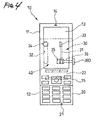
- Fig. 4 is a plan view for showing an extended condition in the first embodiment.
- Fig. 5 is a plan view for representing a swing condition in the first embodiment.
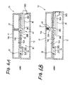
- Figs. 6A and 6B are sectional views for indicating the swing device.
- Fig. 1 is an entire perspective view for indicating a first embodiment of the present invention.
- Fig. 2 is an exploded perspective view for showing a back face of an upper housing and a front face of a lower housing of the first embodiment.
- Fig. 3 is a broken-out perspective view for indicating a swing device in the first embodiment.
- Fig. 4 is a plan view for showing an extended condition in the first
- FIG. 7 is a plan view for showing operations of the upper housing and the lower housing until the upper housing and the lower housing are brought into the swing condition.
- Fig. 8 is a partially enlarged sectional view for indicating a first engaging portion which is engaged with a second rail under the swing condition.
- a portable terminal 10 of the first embodiment is provided with an upper housing 11 having a substantially rectangular shape (as viewed in plane), and a lower housing 12 having a substantially rectangular shape (as viewed in plane).
- the lower housing 12 is coupled via a coupling portion 30 to the upper housing 11.
- the upper housing 11 is equipped with a display unit 13 such as an LCD, a receiver 14, and a first sub-operation unit 15 on a front face 11A of the upper housing 11. While the display unit 13 is made in a rectangular shape, the display unit 13 is arranged along a longitudinal direction of the upper housing 11 in such a manner that a long edge of the display unit 13 is directed to the longitudinal direction.
- the lower housing 12 is equipped with a main operation unit 20 where various sorts of keys are arrayed; a telephone communication-purpose microphone 21; and a second sub-operation unit 22 on a front face 12A of the lower housing 12.
- a circuit board where a control unit, a communication unit, and the like are provided, and an antenna connected to the above-described communication unit are stored. It should be understood that the electric circuits such as the control unit and the communication unit are not always mounted on the circuit board installed in the lower housing 12, but may be alternatively mounted on the circuit board installed in the upper housing 11.
- the coupling portion 30 is provided with a first rail 31, a second rail 32, which are provided in the front face 12A of the lower housing 12; and a first engaging portion 33 and a second engaging portion 34, which are provided on the back face 11B of the upper housing 11 and are engaged with the first rail 31 and the second rail 32, respectively.
- the first rail 31 and the second rail 32 correspond to elongated holes which are formed in the front face 12A of the lower housing 12, and are arranged along the longitudinal direction of the lower housing 12, and also, arranged parallel to each other.
- These first rail 31 and second rail 32 are arranged in an offset mode along a width direction thereof with respect to a center line along the longitudinal direction of the lower housing 12.
- the first engaging portion 33 is made in such a substantially rectangular parallelepiped form that a sectional shape having a substantially U-shape is continued.
- the second engaging portion 34 is made in such a substantially circular cylinder with a stepped portion that a flange portion 34B is provided on an edge portion of an axial portion 34A.
- the first housing 11 is coupled to the second housing 12; and since the first engaging portion 33 and the second engaging portion 34 are slid along the first rail 31 and the second rail 32 respectively, either a stacked layer condition (namely, condition shown in Fig. 1 ) or an extended condition (namely condition shown in Fig. 4 ) can be selected. Under the stacked layer condition, the first housing 11 is stacked on the second housing 12. Under the extended condition, the upper housing 11 and the lower housing 12 are arrayed with a stepped portion along the longitudinal direction. It should be noted that when the portable terminal 10 is brought into the stacked layer condition and the extended condition, the second sub-operation portion 22 is concealed by the upper housing 11.
- a swing condition can be selected from the portable condition by a swing device 40 constructed based upon the inventive idea of the present invention.
- both the upper housing 11 and the lower housing 12 are relatively rotated, while such a line along the stacked layer direction of the upper housing 11 and the lower housing 12 is defined as a center.
- the portable terminal 10 can display TV broadcasting programs such as ground wave TV broadcast and satellite TV broadcast, and can display still images, and also, can reproduce moving pictures on the display unit 13 arranged in such a manner that the longer edge of this display unit 13 is arranged along a lateral direction thereof.
- the second sub-operation unit 22 is exposed, so that sound volume can be controlled, color hue can be controlled, tuning operation can be performed, and multiplexed broadcasting programs can be selected.
- the swing device 40 is equipped with an opening portion 35 having a rectangular shape; a closing member 36 for closing the opening portion 35; and an urging member 37.
- the opening portion 35 is formed in an edge portion of the first rail 31 on the side of the main operation unit (lower portion in Fig. 3 ) along the longitudinal direction.
- the urging member 37 energizes the first engaging portion 33 in such a direction along which the first engaging portion 33 is projected from the back face 11B of the upper housing 11.
- the closing member 36 is equipped with a main body 36A, a claw portion 36B, a base portion 36C, and a button portion 36D.
- the main body 36A is arranged to be intersected with respect to the first rail 31 within the lower housing 12.
- the claw portion 36B is coupled to a tip portion of the main body 36A in the lower housing 12.
- the base portion 36C is arranged to be adjacent with respect to the claw portion 36B along the main body 36A.
- the button portion 36D of the main body 36A is provided outside the lower housing 12.
- the closing member 36 is illustrated by constructing the main body 36A, the claw portion 36B, the base portion 36C, and the button portion 36D as an integral component.
- these individual components may be constructed by employing such materials, and then these individual components may be formed in one body, while considering strengths, outer appearances, and sliding characteristics of these materials.
- the claw portion 36B has an inverse "L"-shape
- the claw portion 36B is arranged in such a manner that an upper surface 36E of this claw portion 36B constitutes the same surface as the surface 12A of the lower housing 12.
- a thicker thickness dimension of the claw portion 36B is made substantially equal to a thicker thickness dimension of the front face 12A of the lower housing 12.
- the base portion 36C is arranged in accordance with the below-mentioned manner: That is, an inclination surface 36F of the base portion is provided opposite to the claw portion 36B, and an upper surface 36G thereof constitutes the same surface as the front face 12A of the lower housing 12.
- a separation dimension between the claw portion 36B and the base portion 36C corresponds to a width dimension "W1" of the first rail 31.
- a tip edge of the claw portion 36B is maintained at a position along an extension line of an opening edge of the first rail 31 by an urging means (not shown), and a stopper, or the like (not shown) , provided on the main body 36A.
- a first inclination surface 33B is provided along as edge line thereof, and second inclination surface 33C is provided on an edge along the longitudinal direction, while a dimension "L" along the longitudinal direction corresponds to a width dimension "W2" of the second rail 32. Then, the first engaging portion 33 is engaged with the first rail 31 in such a manner that the first inclination surface 33B is directed to such a direction along which the first inclination surface 33B is separated with respect to the second rail 32, and also, the second inclination surface 33C is directed to the side of the main operation unit 20 (namely, lower direction shown in Fig. 3 ).
- the swing device 40 which causes the portable condition of the portable terminal 10 to be transferred to the swing condition thereof.
- the first engaging portion 33 is projected from the back face 11B of the upper housing 11 by the urging member 37.
- the groove 33A of the first engaging portion 33 is engaged with the claw portion 36B of the closing member 36, and also, the first inclination surface 33B of the first engaging portion 33 has abutted against the base portion inclination surface 36F of the base portion 36C.
- the exposed area on the front face 12A of the lower housing 12 under the swing condition can be increased, so that the second sub-operation unit 22 having superior operability can be installed.
- the second inclination surface 33C of the first engaging portion 33 is faced to the opening edge portion of the second rail 32.
- the swing condition of the portable terminal 10 is transferred to the portable condition, namely in such a case that the upper housing 11 is rotated along the clockwise direction while the axial line of the second engaging portion 34 is set as the center with respect to the lower housing 12
- the first engaging portion 33 is embedded into the upper housing 11 while the first engaging portion 33 compresses the urging member 37 by the second inclination surface 33c which abuts against the opening edge portion of the second rail 32, and while the first engaging portion 33 is slid on the front face 12A of the lower housing 12, the upper housing 11 can be rotated with respect to the lower housing 12.
- the first engaging portion 33 and the second engaging portion 34 are engaged with respect to the first rail 31 and the second rail 32 respectively, which are located parallel to each other.
- plays and the like can be suppressed, and a predetermined strength can be secured, as compared with those of the conventional stricture in which the engaging portion is engaged with one piece of the rail.
- the first rail 31 and the second rail 32 are concealed under the portable condition, under the extended condition, and under the swing condition.
- a superior outer appearance characteristic under the swing condition can be achieved, and also, since there is a small possibility that dirt and dusts are entered into the first rail 31 and the second rail 32, there is a small risk that an operation problem of the coupling portion 30 caused by the dirt and dusts may occur.
- the first engaging portion 33 can be engaged with the second rail 32 under the swing condition.
- the swing condition can be firmly maintained, so that the better TV broadcasting program display environment such as ground wave TV broadcast and satellite TV broadcast, the better still picture display environment, and the superior moving picture reproducing environment can be achieved.
- both the first rail 31 and the second rail 32 are arranged in the offset mode, when the operation condition of the portable terminal 10 is moved from the portable condition to the swing condition, both the first rail 31 and the second rail 32 can be concealed, and the exposed area of the front face 12A of the lower housing 12 under the swing condition can be increased, so that the second sub-operation unit 22 having the superior operability can be installed.
- the first engaging portion 68 is embedded into the upper housing 11 via the opening portion 35 formed in the first rail 31 so as to release the engagement of the first engaging portion 33 with respect to the first rail 31.
- a space efficiency is not lowered without giving an adverse influence to the internal space of the upper housing 11.
- this first embodiment has mainly described that the structural elements are rotated along the counterclockwise direction. Alternatively, since the structural elements are arranged in a symmetrical manner between a right side and a left side, these structural elements may be rotated along the clockwise direction. Also, in the first embodiment, when the push-button type mechanism closing member is released, even any other mechanisms than the push button type mechanism closing member may be alternatively realized, for instance, may be alternatively realized by a slide type releasing mechanism.
- both a first rail 61 and a second rail 62 have the same shapes and the same dimensions, which constitute a coupling portion 60, whereas both a first engaging portion 63 and a second engage portion 64 have the same shapes and the same dimensions of circular cylinders with stepped portions.
- the first rail 61 and the second rail 62 are arranged on the front face 12A of the lower housing 12 in an offset mode.
- a guide rail 71 is provided which is communicated to the first rail 61 and the second rail 62.
- the guide rail 71 is formed in an arc shape while an edge portion in the second rail 62 on the side of the main operation unit 20.
- An edge portion in the first rail 61 on the side of the main operation unit 20 is communicated with an edge portion in the second rail 62 on such a side apart from the main operation unit 20.
- this portable terminal 50 has basically contained a similar structure to that of the above-described portable terminal 10 according to the first embodiment.
- plays and the like of the coupling portion 68 can be suppressed, and a predetermined strength can be secured; superior outer appearance characteristics under the swing condition, under the portable condition, and under the extended condition can be achieved; and also, since there is a small possibility that dirt and dusts are entered, such a similar effect can be achieved that there is a small risk that an operation problem of the coupling portion 60 caused by the dirt and dusts may occur.
- the swing device 70 can be accomplished. As a consequence, the internal spaces of both the upper housing 11 and the lower hosing 12 can be effectively utilized.
- the present invention is suitably applied to such a portable terminal. That is, since an upper housing and a lower housing stacked on the upper housing are relatively moved along a planar direction thereof, the portable terminal is brought into an extended condition; and also, since the upper hosing and the lower housing are relatively rotated while a line along a stacking direction is defined as a center, the portable terminal is brought into a swing condition.
Landscapes
- Engineering & Computer Science (AREA)
- Signal Processing (AREA)
- Telephone Set Structure (AREA)
- Casings For Electric Apparatus (AREA)
Applications Claiming Priority (2)
| Application Number | Priority Date | Filing Date | Title |
|---|---|---|---|
| JP2005370614A JP4588625B2 (ja) | 2005-12-22 | 2005-12-22 | 携帯端末 |
| PCT/JP2006/324013 WO2007072669A1 (fr) | 2005-12-22 | 2006-11-30 | Terminal mobile |
Publications (2)
| Publication Number | Publication Date |
|---|---|
| EP1965570A1 true EP1965570A1 (fr) | 2008-09-03 |
| EP1965570A4 EP1965570A4 (fr) | 2012-06-13 |
Family
ID=38188450
Family Applications (1)
| Application Number | Title | Priority Date | Filing Date |
|---|---|---|---|
| EP06833816A Withdrawn EP1965570A4 (fr) | 2005-12-22 | 2006-11-30 | Terminal mobile |
Country Status (4)
| Country | Link |
|---|---|
| US (1) | US7904127B2 (fr) |
| EP (1) | EP1965570A4 (fr) |
| JP (1) | JP4588625B2 (fr) |
| WO (1) | WO2007072669A1 (fr) |
Cited By (1)
| Publication number | Priority date | Publication date | Assignee | Title |
|---|---|---|---|---|
| EP2293529A3 (fr) * | 2009-08-27 | 2011-09-14 | Funai Electric Co., Ltd. | Terminal portable avec un boîtier coulissant et rotatif |
Families Citing this family (11)
| Publication number | Priority date | Publication date | Assignee | Title |
|---|---|---|---|---|
| JP4802077B2 (ja) | 2006-09-29 | 2011-10-26 | 富士フイルム株式会社 | 携帯機器 |
| US7970444B2 (en) * | 2007-02-28 | 2011-06-28 | Sony Ericsson Mobile Communications Ab | Pivoting mobile terminal |
| US8301201B2 (en) * | 2007-09-03 | 2012-10-30 | Nec Corporation | Cellular phone |
| CN104023097B (zh) | 2007-10-11 | 2016-09-14 | 联想创新有限公司(香港) | 便携式信息处理终端 |
| US8527019B2 (en) | 2008-08-27 | 2013-09-03 | Nec Corporation | Sliding mechanism and sliding device |
| JPWO2010023961A1 (ja) * | 2008-08-29 | 2012-01-26 | 日本電気株式会社 | スライド機構及びこれを備えた携帯型通信端末、並びにスライド移動方法 |
| JPWO2010024086A1 (ja) * | 2008-08-29 | 2012-01-26 | 日本電気株式会社 | スライド機構及びこれを備えた携帯型通信端末、並びにスライド移動方法 |
| JP5424334B2 (ja) * | 2010-02-25 | 2014-02-26 | Necカシオモバイルコミュニケーションズ株式会社 | 電子機器及びスライド装置 |
| CN102255986B (zh) * | 2010-05-20 | 2014-04-30 | 深圳富泰宏精密工业有限公司 | 旋转机构及具有该旋转机构的电子装置 |
| CN102252017A (zh) * | 2010-05-20 | 2011-11-23 | 深圳富泰宏精密工业有限公司 | 旋转机构及具有该旋转机构的电子装置 |
| US8687376B2 (en) * | 2011-04-04 | 2014-04-01 | Nokia Corporation | Rotating and moving mechanism |
Family Cites Families (10)
| Publication number | Priority date | Publication date | Assignee | Title |
|---|---|---|---|---|
| JP3322021B2 (ja) * | 1994-08-22 | 2002-09-09 | カシオ計算機株式会社 | 情報機器 |
| JPH10124214A (ja) * | 1996-10-24 | 1998-05-15 | Canon Inc | 情報処理装置 |
| JP4192024B2 (ja) | 2003-04-17 | 2008-12-03 | 加藤電機株式会社 | 携帯端末用取付装置 |
| US8155718B2 (en) * | 2003-09-03 | 2012-04-10 | Samsung Electronics Co., Ltd. | Sliding/hinge apparatus for sliding/rotating type mobile terminals |
| KR100617690B1 (ko) * | 2003-11-10 | 2006-08-28 | 삼성전자주식회사 | 슬라이딩 타입 휴대용 무선 단말기 |
| US7042711B2 (en) * | 2003-11-18 | 2006-05-09 | Kabushiki Kaisha Toshiba | Multi-functional electronic device with a continuously accessible pointing device |
| US7092246B2 (en) * | 2003-11-18 | 2006-08-15 | Kabushiki Kaisha Toshiba | Apparatus for connecting a display to a body case of an electronic device |
| JP2006019925A (ja) | 2004-06-30 | 2006-01-19 | Sharp Corp | 携帯情報端末、その開閉操作方法、およびその表示方法 |
| KR100663542B1 (ko) * | 2004-07-30 | 2007-01-02 | 삼성전자주식회사 | 휴대 장치용 슬라이딩 스윙 장치 |
| US20070060220A1 (en) * | 2005-09-14 | 2007-03-15 | An-Szu Hsu | Gliding structure for glide-open type mobile phone |
-
2005
- 2005-12-22 JP JP2005370614A patent/JP4588625B2/ja not_active Expired - Fee Related
-
2006
- 2006-11-30 EP EP06833816A patent/EP1965570A4/fr not_active Withdrawn
- 2006-11-30 US US12/158,518 patent/US7904127B2/en not_active Expired - Fee Related
- 2006-11-30 WO PCT/JP2006/324013 patent/WO2007072669A1/fr not_active Ceased
Cited By (2)
| Publication number | Priority date | Publication date | Assignee | Title |
|---|---|---|---|---|
| EP2293529A3 (fr) * | 2009-08-27 | 2011-09-14 | Funai Electric Co., Ltd. | Terminal portable avec un boîtier coulissant et rotatif |
| US8369071B2 (en) | 2009-08-27 | 2013-02-05 | Funai Electric Co., Ltd. | Portable terminal |
Also Published As
| Publication number | Publication date |
|---|---|
| US7904127B2 (en) | 2011-03-08 |
| EP1965570A4 (fr) | 2012-06-13 |
| JP2007174372A (ja) | 2007-07-05 |
| WO2007072669A1 (fr) | 2007-06-28 |
| JP4588625B2 (ja) | 2010-12-01 |
| US20090298560A1 (en) | 2009-12-03 |
Similar Documents
| Publication | Publication Date | Title |
|---|---|---|
| EP1898606B1 (fr) | Dispositif à charnière doté d'une pluralité d'axes pour un terminal portable et élément de connexion doté d'une pluralité d'axes | |
| US7194290B2 (en) | Portable wireless terminal device | |
| EP1898605B1 (fr) | Dispositif d'entrée à touches pour appareil de communications portable et module coulissant correspondant | |
| EP1768356B1 (fr) | Terminal portatif pliable formant un prisme triangulaire | |
| US20070293286A1 (en) | Sliding module for mobile phone | |
| US7904127B2 (en) | Portable terminal | |
| US20080076480A1 (en) | Swing-type mobile communication terminal and swing device thereof | |
| KR101662322B1 (ko) | 휴대용 단말기의 방수 구조 | |
| EP1871079A2 (fr) | Terminal portable à butoir articulé | |
| US20080039155A1 (en) | Mobile communications device with rotatable screen and qwerty keypad | |
| KR101101073B1 (ko) | 단말기 | |
| US8712487B2 (en) | Sliding-type portable communication device | |
| US7894866B2 (en) | Sliding-type portable terminal | |
| US20070184786A1 (en) | Portable communication terminal for games with foldable keypad | |
| US7986981B2 (en) | Portable terminal with rotatable display | |
| EP1594290B1 (fr) | Terminal doublement pliable | |
| EP1693539A2 (fr) | Charnière pour un téléphone mobile avec un dispositif d'affichage pivotant | |
| US7734314B2 (en) | Slim type portable terminal | |
| KR20110022365A (ko) | 2 개의 힌지축을 구비하는 휴대용 단말기 | |
| CN104023097A (zh) | 便携式信息处理终端 | |
| KR100648643B1 (ko) | 슬라이드형 단말기 | |
| TWI418201B (zh) | 滑蓋結構及應用該滑蓋結構之攜帶式電子裝置 | |
| KR20080096345A (ko) | 2축 힌지 장치를 구비하는 휴대용 단말기 | |
| KR200375653Y1 (ko) | 슬라이딩 기능이 포함된 폴더를 갖는 이동통신 단말기 | |
| CN101094254A (zh) | 用于移动电话的滑动模块 |
Legal Events
| Date | Code | Title | Description |
|---|---|---|---|
| PUAI | Public reference made under article 153(3) epc to a published international application that has entered the european phase |
Free format text: ORIGINAL CODE: 0009012 |
|
| 17P | Request for examination filed |
Effective date: 20080623 |
|
| AK | Designated contracting states |
Kind code of ref document: A1 Designated state(s): DE FR GB |
|
| RAP1 | Party data changed (applicant data changed or rights of an application transferred) |
Owner name: PANASONIC CORPORATION |
|
| RBV | Designated contracting states (corrected) |
Designated state(s): DE FR GB |
|
| A4 | Supplementary search report drawn up and despatched |
Effective date: 20120514 |
|
| RIC1 | Information provided on ipc code assigned before grant |
Ipc: H04M 1/02 20060101AFI20120508BHEP |
|
| DAX | Request for extension of the european patent (deleted) | ||
| STAA | Information on the status of an ep patent application or granted ep patent |
Free format text: STATUS: THE APPLICATION IS DEEMED TO BE WITHDRAWN |
|
| 18D | Application deemed to be withdrawn |
Effective date: 20121211 |