EP1965604A1 - Dispositif magnetostrictif - Google Patents
Dispositif magnetostrictif Download PDFInfo
- Publication number
- EP1965604A1 EP1965604A1 EP06797315A EP06797315A EP1965604A1 EP 1965604 A1 EP1965604 A1 EP 1965604A1 EP 06797315 A EP06797315 A EP 06797315A EP 06797315 A EP06797315 A EP 06797315A EP 1965604 A1 EP1965604 A1 EP 1965604A1
- Authority
- EP
- European Patent Office
- Prior art keywords
- magnetostrictor
- magnetostriction apparatus
- housing
- magnetic field
- external member
- Prior art date
- Legal status (The legal status is an assumption and is not a legal conclusion. Google has not performed a legal analysis and makes no representation as to the accuracy of the status listed.)
- Withdrawn
Links
Images





Classifications
-
- H—ELECTRICITY
- H04—ELECTRIC COMMUNICATION TECHNIQUE
- H04R—LOUDSPEAKERS, MICROPHONES, GRAMOPHONE PICK-UPS OR LIKE ACOUSTIC ELECTROMECHANICAL TRANSDUCERS; ELECTRIC HEARING AIDS; PUBLIC ADDRESS SYSTEMS
- H04R15/00—Magnetostrictive transducers
-
- B—PERFORMING OPERATIONS; TRANSPORTING
- B06—GENERATING OR TRANSMITTING MECHANICAL VIBRATIONS IN GENERAL
- B06B—METHODS OR APPARATUS FOR GENERATING OR TRANSMITTING MECHANICAL VIBRATIONS OF INFRASONIC, SONIC, OR ULTRASONIC FREQUENCY, e.g. FOR PERFORMING MECHANICAL WORK IN GENERAL
- B06B1/00—Methods or apparatus for generating mechanical vibrations of infrasonic, sonic, or ultrasonic frequency
- B06B1/02—Methods or apparatus for generating mechanical vibrations of infrasonic, sonic, or ultrasonic frequency making use of electrical energy
- B06B1/08—Methods or apparatus for generating mechanical vibrations of infrasonic, sonic, or ultrasonic frequency making use of electrical energy operating with magnetostriction
-
- H—ELECTRICITY
- H04—ELECTRIC COMMUNICATION TECHNIQUE
- H04R—LOUDSPEAKERS, MICROPHONES, GRAMOPHONE PICK-UPS OR LIKE ACOUSTIC ELECTROMECHANICAL TRANSDUCERS; ELECTRIC HEARING AIDS; PUBLIC ADDRESS SYSTEMS
- H04R9/00—Transducers of moving-coil, moving-strip, or moving-wire type
- H04R9/02—Details
- H04R9/025—Magnetic circuit
-
- H—ELECTRICITY
- H04—ELECTRIC COMMUNICATION TECHNIQUE
- H04R—LOUDSPEAKERS, MICROPHONES, GRAMOPHONE PICK-UPS OR LIKE ACOUSTIC ELECTROMECHANICAL TRANSDUCERS; ELECTRIC HEARING AIDS; PUBLIC ADDRESS SYSTEMS
- H04R1/00—Details of transducers, loudspeakers or microphones
- H04R1/10—Earpieces; Attachments therefor ; Earphones; Monophonic headphones
- H04R1/1008—Earpieces of the supra-aural or circum-aural type
-
- H—ELECTRICITY
- H04—ELECTRIC COMMUNICATION TECHNIQUE
- H04R—LOUDSPEAKERS, MICROPHONES, GRAMOPHONE PICK-UPS OR LIKE ACOUSTIC ELECTROMECHANICAL TRANSDUCERS; ELECTRIC HEARING AIDS; PUBLIC ADDRESS SYSTEMS
- H04R2400/00—Loudspeakers
- H04R2400/11—Aspects regarding the frame of loudspeaker transducers
-
- H—ELECTRICITY
- H04—ELECTRIC COMMUNICATION TECHNIQUE
- H04R—LOUDSPEAKERS, MICROPHONES, GRAMOPHONE PICK-UPS OR LIKE ACOUSTIC ELECTROMECHANICAL TRANSDUCERS; ELECTRIC HEARING AIDS; PUBLIC ADDRESS SYSTEMS
- H04R2460/00—Details of hearing devices, i.e. of ear- or headphones covered by H04R1/10 or H04R5/033 but not provided for in any of their subgroups, or of hearing aids covered by H04R25/00 but not provided for in any of its subgroups
- H04R2460/13—Hearing devices using bone conduction transducers
-
- H—ELECTRICITY
- H04—ELECTRIC COMMUNICATION TECHNIQUE
- H04R—LOUDSPEAKERS, MICROPHONES, GRAMOPHONE PICK-UPS OR LIKE ACOUSTIC ELECTROMECHANICAL TRANSDUCERS; ELECTRIC HEARING AIDS; PUBLIC ADDRESS SYSTEMS
- H04R25/00—Electric hearing aids
- H04R25/60—Mounting or interconnection of hearing aid parts, e.g. inside tips, housings or to ossicles
- H04R25/604—Mounting or interconnection of hearing aid parts, e.g. inside tips, housings or to ossicles of acoustic or vibrational transducers
- H04R25/606—Mounting or interconnection of hearing aid parts, e.g. inside tips, housings or to ossicles of acoustic or vibrational transducers acting directly on the eardrum, the ossicles or the skull, e.g. mastoid, tooth, maxillary or mandibular bone, or mechanically stimulating the cochlea, e.g. at the oval window
-
- H—ELECTRICITY
- H04—ELECTRIC COMMUNICATION TECHNIQUE
- H04R—LOUDSPEAKERS, MICROPHONES, GRAMOPHONE PICK-UPS OR LIKE ACOUSTIC ELECTROMECHANICAL TRANSDUCERS; ELECTRIC HEARING AIDS; PUBLIC ADDRESS SYSTEMS
- H04R5/00—Stereophonic arrangements
- H04R5/033—Headphones for stereophonic communication
Definitions
- the present invention relates to a magnetostriction apparatus for generating or detecting vibration by using a magnetostrictor.
- a super magnetostrictor By applying an alternate magnetic field to a magnetostrictor, vibration at the same frequency as that of the alternating magnetic field can be generated. It is envisaged that the phenomenon will be exploited in some way.
- a super magnetostrictor could be applied to a bone conduction headphone or a hearing aid (see, for example, patent document No. 1).
- a magnetostrictor-based vibration generator provided in a headphone or a hearing aid be small and lightweight.
- a general purpose of the present invention is to provide a technology for achieving a small and lightweight magnetostriction apparatus.
- a magnetostriction apparatus comprises: a magnetostrictor which expands and contracts in accordance with a magnetic field; a magnetic field generating means which generates the magnetic field; and a housing which holds the magnetostrictor and the magnetic field generating means at predetermined positions, wherein the housing is connected to an external member so that a predetermined pressure is applied to the magnetostrictor by the external member and the housing.
- the external member may include a circuit which supplies a signal for generating the magnetic field to the magnetic field generating means.
- the housing may include a yoke which adjusts a magnetic circuit of the magnetic field generated by the magnetic field generating means.
- a magnetostriction apparatus comprises: a magnetostrictor the magnetic characteristic of which varies in accordance with variation applied from outside; detecting means which detects variation in the magnetic characteristic in the form an electrical signal; a housing which holds the magnetostrictor and the detecting means at predetermined positions, wherein the housing is connected to an external member so as that a predetermined pressure is applied to the magnetostrictor by the external member and the housing.
- the external member may include a circuit which acquires the electrical signal from the detecting means.
- the magnetostriction apparatus may not comprise a structure which supports an end of the magnetostrictor opposite to an end supported by the housing and applies a predetermined pressure to the magnetostrictor.
- the housing may include a yoke for creating a closed magnetic path within the housing.
- the face of the housing where the magnetostriction apparatus is connected to the external member may be open, and the magnetostriction apparatus may be connected to the external member such that the end of the magnetostrictor facing the external member, or a constituting member provided in the magnetostrictor to face the external member comes into contact with the external member.
- the magnetostriction apparatus may further comprise a vibrating unit which conducts vibration at an end of the magnetostrictor opposite to an end facing the external member, outside the magnetostriction apparatus.
- a small and lightweight magnetostriction apparatus can be achieved.
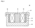
- FIG. 1 shows the structure of a related-art magnetostriction apparatus.
- a related-art magnetostriction apparatus 90 is provided with a magnetostrictor 91, a coil 92, a bias magnet 93, a cap 94 and a case 95.
- the magnetostrictor 91 has a substantially cylindrical shape and is displaced such that it expands and contracts in the direction of height in accordance with a magnetic field generated by the coil 92 and the bias magnet 93.
- the magnetostrictor 91 is provided substantially at the center of the case 95 so that the height thereof is aligned with the depth of the substantially cylindrical case 95.
- the coil 92 is provided around the magnetostrictor 91.
- An electric current supplied from an external drive generates a magnetic field around the magnetostrictor 91.
- the bias magnet 93 is provided to provide a bias magnetic field of a predetermined intensity around the magnetostrictor 91 on a permanent basis.
- the cap 94 is substantially disk-shaped and is provided to seal the case 95 which contains the magnetostrictor 91, the coil 92 and the bias magnet 93 inside.
- An engagement groove 96 is formed toward the top of the side wall of the case 95.
- a latch part 97 of the cap 94 is latched by the engagement groove 96 so as to secure the cap 94 and the case 95 to each other.
- the magnetostrictor 91 is pressed from above and from below by the cap 94 and the case 95, respectively, so as to undergoes certain prestress.
- the cap 94 vibrates as a result of the expansion and contraction of the magnetostrictor 91, and the vibration is conducted outside via the cap 94.
- the magnetostriction apparatus 90 shown in Fig. 1 is used in a headphone, the cap 94 is pressed against the neighborhood of the ear so as to conduct the vibration generated by the magnetostrictor 91 to the head via the cap 94.
- the cap 94 is formed so as to have larger elasticity than the bottom of the case 95. This prevents the vibration of the magnetostrictor 91 from being absorbed by the bottom of the case 95 and ensures that the vibration is efficiently conducted to a target object (e.g., the head of the user) via the cap 94.
- Fig. 2 shows a table showing the characteristics of a super magnetostrictive material and a piezoelectric material.
- a super magnetostrictive material such as terbium-dysprosium-iron (TbDyFe) has superior characteristics than a piezoelectric material such as lead zirconate titanate (PZT: PbZrO3-PbTiO3) as described below.
- a super magnetostrictive material is characterized by larger stress developed therein and relatively large displacement. Accordingly, vibration generated in a super magnetostrictor can be efficiently conducted outside. Further, since the drive voltage is lower, the power consumption is smaller. Moreover, since the Curie point is higher, it can be used in a high temperature. Since the super magnetostrictor vibrates in the presence of a magnetic field, the driven part is not in contact with a power supply. As such, the material is highly safe to use.
- a super magnetostrictive material is characterized by large stress developed therein and so can properly conduct low-frequency, high-energy vibration outside.
- An additional benefit of high response speed enables the material to properly follow a high-frequency input signal to generate vibration.
- a flat characteristic is achieved over a wide frequency range. This is particularly advantageous in a headphone or a speaker in which the material is used.
- a related-art headphone using a piezoelectric material can only generate sound up to about 5-20 kHz.
- sound at 50 kHz or higher can be generated. It is said that humans can hear sound with a frequency of up to about 20 kHz.
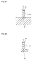
- FIGs. 3A and 3B schematically show how a magnetostrictor vibrates.
- a fixed end 98 of the magnetostrictor 91
- the magnetostrictor 91 expands and contracts only toward or away from the other end (hereinafter, referred to as an "output end"). Therefore, vibration occurring when the magnetostrictor 91 expands or contracts is efficiently conducted outside via the output end 99.
- the fixed end 98 vibrates due to the fact that the member supporting the fixed end 98 of the magnetostrictor 91 is elastic or lightweight as shown in Fig.
- the member in contact with the fixed end 98 of the magnetostrictor 91 e.g., the case 95 of the magnetostriction apparatus 90 of Fig. 1
- the challenge is quite unique to a magnetostrictor, which is characterized by greater stress developed therein than in a piezoelectric device. Such a challenge has not even been aware of by developers of sound conduction apparatuses that use piezoelectric devices.
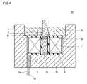
- FIG. 4 shows the structure of a magnetostriction apparatus improved in view of the above-mentioned challenge.
- a magnetostriction apparatus 20 includes a super magnetostrictor 1, a bias magnet 2 (an upper bias magnet 2a and a lower bias magnet 2b), a bobbin 3, a coil 4, electrical leads 5a and 5b, a vibrating rod 6, a prestress cap 7a, a case 7b and an elastic member (helical spring) 9.
- the super magnetostrictor 1 is used as a vibration transducer for converting a signal derived from sound into vibration.
- the super magnetostrictor 1 has a substantially cylindrical shape and is provided with the upper bias magnet 2a on its top and the lower bias magnet 2b on its bottom.
- the super magnetostrictor 1 is sandwiched between the upper bias magnet 2a and the lower bias magnet 2b and accommodated in the case 7b.
- the super magnetostrictor 1 is permanently exposed to a bias magnetic field generated by the upper bias magnet 2a and the lower bias magnet 2b (i.e., the bias magnetic field permanently penetrates the super magnetostrictor 1).
- the super magnetostrictor 1 is ensured that prestress is permanently exerted on the super magnetostrictor 1 by accommodating it in the case 7b, supporting the bottom thereof by the case 7b, and pressing a vibrating rod 6 against the top thereof with the elastic force of the elastic member 9.
- the super magnetostrictor 1 is subjected to a variable magnetic field generated by the coil 4 disposed around the super magnetostrictor 1, while also being permanently exposed to a bias magnetic field and prestress as described above. As a result, the super magnetostrictor 1 generates vibration in response to an input electric signal.
- the coil 4 is formed by wrapping a conductor line around the body of the bobbin 3 as a shaft.
- the bobbin 3 is made of a material such as glass substrate or polycarbonate.
- the coil 4 As an electrical signal is input to the conductor line via the electrical lead, the coil 4 generates a magnetic field 4 accordingly.
- the variable magnetic field generated by the coil 4 By allowing the variable magnetic field generated by the coil 4 to penetrate the super magnetostrictor 1, the super magnetostrictor 1 expands or contracts in accordance with the intensity of the variable magnetic field, resulting in an output of vibration.
- the vibrating rod 6 is mechanically connected to the super magnetostrictor 1 via the upper bias magnet 2a so as to conduct the vibration output from the super magnetostrictor 1 outside by another end.
- the vibrating rod 61 is provided with a flange part 61.
- the flange part 61 is urged by the elastic member 9 so as to be pressed against the upper bias magnet 2a.
- the pressing force is applied to the super magnetostrictor 1 via the upper bias magnet 2a.
- the flange part 61 and the elastic member 9 prevent the entirety of the vibrating rod 6 from slipping out of the case 7b and the prestress cap 7a.
- the case 7b is a container (or a body) which accommodates the super magnetostrictor 1, the upper bias magnet 2a, the lower bias magnet 2b, the bobbin 3, the coil 4, the vibrating rod 6 and the elastic member 9 assembled in a predetermined configuration.
- the prestress cap 7a is fixed to the case 7a by a spring mechanism, welding, caulking, resin cure or the like. In the process of fixing the prestress cap 7a to the case 7b, prestress is applied to the super magnetostrictor via the elastic member 9. By applying prestress to the super magnetostrictor 1, efficiency of transducing between an electric signal and vibration is improved.
- the prestress cap 7a and the case 7b are preferably formed of a magnetic material so as not to leak the internal magnetic field outside and to generate the magnetic field inside efficiently.
- Fig. 5 shows the structure of a headphone as an example of an electronic device provided with the magnetostriction apparatus 20 as a vibration generator.
- a headphone 100 is provided with a main body 110, a magnetostriction apparatus 20 and a vibrating pad 28.
- the main body 110 includes a circuit 29 for transmitting an electric signal input from a player or the like outside the appliance to the coil of the magnetostriction apparatus 20.
- the vibrating pad 28 is fitted to the vibrating rod 6 of the magnetostriction apparatus 20 and conducts the vibration conducted from the vibrating rod 6 to the skull bone in the vicinity of the user's ear. The user can recognize the vibration conducted from the surface of the vibrating pad 28 as sound through bone conduction.
- We built a prototype of the bone-conduction headphone 100 shown in Fig. 5 and found that a wide tonal range from bass to treble is reproduced with a high fidelity, resulting in excellent acoustic property.
- a magnetostriction apparatus capable of generating vibration efficiently over a wide frequency range was thus achieved.
- products such as headphones and cell phones which owe their popularity to small size and lightweight
- a slight increase in size or weight over the prior product may negatively affect consumers' desired to purchase the product. This is partly demonstrated by the fact that headphones that use piezoelectric devices are commercialized in advance of those with magnetostrictors, which is superior in performance.
- the super magnetostrictor 1 Since the super magnetostrictor 1 is of a cylindrical shape and is displaced in the height direction, it is necessary to connect moving components and the height of the super magnetostrictor 1 in series. Further, in order to impart necessary vibration to a target object, the super magnetostrictor 1 should have a certain height. Therefore, a constraint is imposed in reducing its size in the height direction. Accordingly, the size and weight of the case 7b and the prestress cap 7a, which occupy a large portion of the total weight of the magnetostriction apparatus 20, need to be reduced. However, the case 7b should also have a certain inertial mass in order to maintain the low-frequency characteristic. We have arrived at a technology capable of meeting these incompatible requirements through various experiments, trials and errors.
- Fig. 6 shows the structure of a magnetostriction apparatus according to the embodiment.
- a magnetostriction apparatus 30 according to the embodiment is provided with a housing 8 in place of the prestress cap 7a and the case 7b.
- the housing 8 is provided with a screw part 81, which is an example of a connecting mechanism fitting the magnetostriction apparatus 30 to the main body of the electronic device in which the magnetostriction apparatus 30 is provided. That is, the components of the magnetostriction apparatus 30 are accommodated in the housing 8 before being fitted to the main body of the electronic device through the screw part 81.
- the housing 8 includes a yoke formed of, for example, a soft iron plate in order to adjust a magnetic circuit of a magnetic field generated by the bias magnet 2, the coil 4 and the electrical leads 5a and 5b and to amplify a magnetic field.
- the bias magnet 2, the coil 4 and the electrical leads 5a and 5b constitute a magnetic field generating means.
- the yoke creates a closed magnetic path within the housing 8 and prevents a magnetic field from leaking outside.
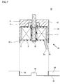
- FIG. 7 schematically shows the structure of an electronic device provided with the magnetostriction apparatus 30 shown in Fig. 6 .
- a main body 40 of the electronic device 50 is provided with a screw part 41, which is an example of a connecting mechanism for attaching the magnetostriction apparatus 30.
- the connecting mechanism may connect the magnetostriction apparatus 30 to the main body 40 by welding, caulking, resin cure or the like.
- the end of the housing 8 facing the main body 40 is open.
- the lower bias magnet 2b comes into direct contact with the main body 40.
- a projection 42 is provided in a position of the main body 40 which comes into contact with the lower bias magnet 2b.
- the electrical leads 5a and 5b are connected to a circuit 49 of the main body 40 so that an electrical signal supplied from the circuit 49 is transmitted to the coil 4.
- the case 7b is assigned the function of supporting the fixed end of the super magnetostrictor 1.
- the main body 40 of the electronic device 50 which includes, for example, a circuit to provide an electric signal to the magnetostriction apparatus 30, is assigned that function. That is, the housing 8 is provided to accommodate components such as the super magnetostrictor 1, the coil 4, the bias magnet 2 and the elastic member 9 and is not assigned the function of supporting the fixed end of the super magnetostrictor 1 or the function of applying prestress to the super magnetostrictor 1.
- a related-art approach requires a magnetostriction apparatus as a prerequisite, with a case and a prestress cap being built in and building the magnetostriction apparatus in, for example, an electronic device.
- the magnetostriction apparatus 30 of the embodiment can be fitted to any main body 40 so long as the main body 40 has sufficient mass and hardness. Accordingly, electronic devices using the magnetostriction apparatus 30 can be designed flexibly.
- an inertial mass 13.8 times or larger than the moving weight should be provided at the fixed end in order to suppress vibration at the fixed end of the super magnetostrictor and efficiently conduct the vibration at the output end outside.
- the main body 40 should have mass approximately 13.8 times or larger - or, preferably, 21 times or larger, or, more preferably, 69 times or larger - than the total mass of the super magnetostrictor 1, the bias magnet 2, the elastic member 9 and the vibrating rod 6. If an additional part vibrated by the vibrating rod 6 (e.g., a vibrating pad for fitting the headphone close to the ear of the user) is provided, the mass of such a part shall be included in the mass of the vibrating rod 6.
- the mass of constituent members that can be regarded as being mechanically integral with the main body 40 may be included in the mass of the main body 40.
- the member (in the example of Fig. 7 , the projection 42) in the main body 40 with which the structure of the fixed end comes into contact desirably has sufficient hardness to suppress vibration at the fixed end of the super magnetostrictor 1.
- the housing 8 is preferably made of a magnetic material. In case the magnetostriction apparatus 30 is used in a headphone or the like, however, the housing 8 may not be formed of a magnetic material because the magnetic field generated is not so intense. In this case, the housing 8 may be formed of a light material to achieve lightweight.
- Fig. 8 shows the structure of a headphone as an example of the electronic device 50 provided with the magnetostriction apparatus 30 shown in Fig. 6 .
- a headphone 200 is provided with the magnetostriction apparatus 30 of an open type shown in Fig. 6 instead of the magnetostriction apparatus 20 of a closed type provided in the headphone 100 shown in Fig. 5 .
- the inertial mass is preferably about 3.4 times or larger than the moving mass.
- the inertial mass of the fixed end including the mass of the main body, is about 90 g, which is about 69 times (9 times, if the vibrating pad is included) larger than the moving mass. This demonstrates that the headphone 100 has a characteristic superior to the bone-conduction headphone according to the related art.
- the magnetostriction apparatus 30 of an open type shown in Fig. 6 weighing as little as 12.8 g. Since the mass of prototype magnetostriction apparatus 20 is 22.2 g, the mass of the magnetostriction apparatus is reduced to almost half. It is known from the experiment already mentioned that an excellent frequency characteristic is obtained by providing at the fixed end an inertial mass 13.8 times or larger - or, more preferably, 69 times or larger - than the moving mass. This shows that the main body to which the magnetostriction apparatus 30 is attached is required to have the mass.
- the mass of the main body may be 17.9 g or greater.
- the headphone 200 is significantly lighter than the headphone 100, while offering excellent acoustic property as the headphone 100.
- the housing 8 of the prototype is formed of a metal. If the coil is contained in a yoke formed of Permalloy or the like to create a closed magnetic path, the housing 8 may be formed of a light material such as resin. This can further reduce the mass of the magnetostriction apparatus 30 and, ultimately, the mass of the apparatus like a headphone as a whole.
- Fig. 9 shows the structure of the electronic device 50 according to a variation of the embodiment.
- the magnetostriction apparatus 30 shown in Fig. 9 is further provided with a bottom plate 11 in addition to the components of the magnetostriction apparatus 30 shown in Fig. 7 .
- the bottom plate 11 may be formed of a plate with waterproof finish for preventing drops of water from invading the magnetostriction apparatus 30 or the main body 40.
- the bottom plate 11 may be formed of a magnetic material to prevent leakage of magnetic field to the main body 40. Since the magnetostriction apparatus 30 of this variation is provided with the bottom plate 11 facing the main body 40, the apparatus is of a closed type instead of an open type.
- the bottom plate 11 need not have an inertial mass necessary to suppress vibration at the fixed end of the super magnetostrictor 1.
- the bottom plate 11 is not provided to suppress vibration at the fixed end of the super magnetostrictor 1.
- the inertial mass necessary to suppress vibration may be in the main body 40 of the electronic device 50.
- the main body 40 shall have the weight 16.8 times or larger - or, preferably, 21 times or larger, or, more preferably, 69 times or larger - than the moving mass.
- the mass of the bottom plate 11 may be included in the mass of the main body 40. If there is some member provided between the main body 40 and the super magnetostrictor 1 in addition to the bottom plate 11, the mass of that member may be included in the mass of the main body 40. What is essential is that the fixed end of the super magnetostrictor 1 be provided with sufficient mass and hardness to suppress vibration at the fixed end. With this, vibration of the super magnetostrictor 1 is efficiently conducted outside. Also, the magnetostriction apparatus 30 is allowed to exhibit its excellent frequency characteristic in this way. A particular benefit of the magnetostriction apparatus 30 used in the headphone 200 is that sound quality is improved.
- one super magnetostrictor 1 is provided in the magnetostriction apparatus 30.
- multiple super magnetostrictors may be provided so long as the main body 40 has enough inertial mass.
- the size of the super magnetostrictor 1 is as desired.
- the magnetostriction apparatus 30 may be used as a vibration detector.
- the vibrating rod 6 has the function of conducting vibration applied from outside to the super magnetostrictor 1.
- the coil 4 functions as a detecting means for detecting variation in magnetic characteristic of the super magnetostrictor 1 in accordance with the vibration applied from outside, in the form of an electrical signal.
- the housing 8 is provided with a screw part 81 functioning as a connecting means for connecting the apparatus to the main body 40.
- the hardness and mass of main body 40 is sufficient to suppress vibration at the end of the main body 40 as the super magnetostrictor 1 is vibrated due to the vibration applied from outside. With this, vibration over a wide frequency range can be accurately detected.
- the present invention is applicable to an electronic device for generating or detecting vibration by using a magnetostrictor.
Landscapes
- Engineering & Computer Science (AREA)
- Physics & Mathematics (AREA)
- Acoustics & Sound (AREA)
- Signal Processing (AREA)
- Mechanical Engineering (AREA)
- General Health & Medical Sciences (AREA)
- Health & Medical Sciences (AREA)
- Otolaryngology (AREA)
- Neurosurgery (AREA)
- Apparatuses For Generation Of Mechanical Vibrations (AREA)
- Measuring Fluid Pressure (AREA)
- Details Of Audible-Bandwidth Transducers (AREA)
- Length Measuring Devices Characterised By Use Of Acoustic Means (AREA)
Applications Claiming Priority (2)
| Application Number | Priority Date | Filing Date | Title |
|---|---|---|---|
| JP2005370919 | 2005-12-22 | ||
| PCT/JP2006/317373 WO2007072610A1 (fr) | 2005-12-22 | 2006-09-01 | Dispositif magnetostrictif |
Publications (1)
| Publication Number | Publication Date |
|---|---|
| EP1965604A1 true EP1965604A1 (fr) | 2008-09-03 |
Family
ID=38188394
Family Applications (1)
| Application Number | Title | Priority Date | Filing Date |
|---|---|---|---|
| EP06797315A Withdrawn EP1965604A1 (fr) | 2005-12-22 | 2006-09-01 | Dispositif magnetostrictif |
Country Status (9)
| Country | Link |
|---|---|
| US (1) | US20100141248A1 (fr) |
| EP (1) | EP1965604A1 (fr) |
| JP (2) | JP4058462B2 (fr) |
| KR (1) | KR20080081332A (fr) |
| CN (1) | CN101366320A (fr) |
| CA (1) | CA2634689A1 (fr) |
| EA (1) | EA200870106A1 (fr) |
| NO (1) | NO20083199L (fr) |
| WO (2) | WO2007072610A1 (fr) |
Cited By (4)
| Publication number | Priority date | Publication date | Assignee | Title |
|---|---|---|---|---|
| EP2974377A4 (fr) * | 2013-03-15 | 2016-11-16 | Cochlear Ltd | Transducteur électromagnétique ayant une géométrie interne spécifique |
| US10178484B2 (en) | 2011-03-16 | 2019-01-08 | Cochlear Limited | Bone conduction device including a balanced electromagnetic actuator having radial and axial air gaps |
| US11035830B2 (en) | 2017-06-23 | 2021-06-15 | Cochlear Limited | Electromagnetic transducer with dual flux |
| US11778385B2 (en) | 2017-06-23 | 2023-10-03 | Cochlear Limited | Electromagnetic transducer with non-axial air gap |
Families Citing this family (18)
| Publication number | Priority date | Publication date | Assignee | Title |
|---|---|---|---|---|
| KR100986562B1 (ko) * | 2009-01-30 | 2010-10-07 | 충남대학교산학협력단 | 자기 변형 구동기를 이용한 평판 진동형 스피커 |
| US8649541B2 (en) * | 2011-07-11 | 2014-02-11 | Starkey Laboratories, Inc. | Hearing aid with magnetostrictive electroactive sensor |
| CN103024650A (zh) * | 2012-12-19 | 2013-04-03 | 中国民用航空飞行学院 | 一种参量扬声器用超磁致伸缩稀土换能器 |
| CN104076094A (zh) * | 2014-05-15 | 2014-10-01 | 厦门大学 | 一种激励和接收超声水平剪切导波的超声换能探头 |
| US20160089298A1 (en) | 2014-09-29 | 2016-03-31 | Otolith Sound Inc | Device for Mitigating Motion Sickness and Other Responses to Inconsistent Sensory Information |
| GB2552467A (en) * | 2016-07-20 | 2018-01-31 | Bae Systems Plc | Housing for connecting a transducer to a substrate |
| US11284205B2 (en) | 2016-11-14 | 2022-03-22 | Otolith Sound Inc. | Systems, devices, and methods for treating vestibular conditions |
| US10398897B2 (en) * | 2016-11-14 | 2019-09-03 | Otolith Sound Inc. | Systems, devices, and methods for treating vestibular conditions |
| CN109550674B (zh) * | 2017-09-25 | 2021-09-21 | 佛山市顺德区美的电热电器制造有限公司 | 磁致伸缩声波发生装置及具有它的烹饪设备 |
| CN109549448B (zh) * | 2017-09-25 | 2021-12-21 | 佛山市顺德区美的电热电器制造有限公司 | 烹饪设备 |
| CN109549452A (zh) * | 2017-09-25 | 2019-04-02 | 佛山市顺德区美的电热电器制造有限公司 | 烹饪容器、烹饪设备和烹饪方法 |
| CN108541424B (zh) * | 2018-03-26 | 2020-10-09 | 民本农机有限公司 | 一种定量分种器及其播种装置 |
| CN110058246B (zh) * | 2019-05-10 | 2024-05-31 | 苏州静声泰科技有限公司 | 一种小型化低频水声换能器 |
| CN112994514A (zh) * | 2019-12-17 | 2021-06-18 | 重庆璀陆探测技术有限公司 | 超磁致伸缩振源 |
| CN111457832B (zh) * | 2020-05-18 | 2021-06-29 | 上海凯佛自动化仪表有限公司 | 一种抬升式磁致伸缩位移变送器 |
| JP7768504B2 (ja) * | 2021-12-27 | 2025-11-12 | 株式会社あおごち | ヘルメット用通話装置 |
| CN217693033U (zh) * | 2021-12-29 | 2022-10-28 | 瑞声开泰声学科技(上海)有限公司 | 具有振动功能的电子设备 |
| CN121254157B (zh) * | 2025-12-08 | 2026-03-10 | 湖南大学 | 超磁致伸缩棒材多物理场耦合动态特性监测系统 |
Family Cites Families (11)
| Publication number | Priority date | Publication date | Assignee | Title |
|---|---|---|---|---|
| KR200156789Y1 (ko) * | 1992-08-06 | 1999-09-01 | 요트.게.아. 롤페즈 | 다층구조를 가진 자기헤드와 그 제조방법 |
| JP3497320B2 (ja) * | 1996-03-27 | 2004-02-16 | Tdk株式会社 | 骨導式音声伝達装置 |
| US6429650B1 (en) * | 1999-03-17 | 2002-08-06 | Southwest Research Institute | Method and apparatus generating and detecting torsional wave inspection of pipes or tubes |
| JP2001258095A (ja) * | 2000-03-09 | 2001-09-21 | Material & Intelligent Device Kenkyusho:Kk | 音響器具及び磁歪振動子の駆動方法 |
| JP2004527168A (ja) * | 2001-03-19 | 2004-09-02 | ニューランズ テクノロジー リミテッド | 磁歪アクチュエータ |
| US6884519B2 (en) * | 2001-09-17 | 2005-04-26 | Showa Denko K.K. | Magnetic recording medium, including an HCP structured Ni-alloy control film method of manufacture therefor, and magnetic read/write apparatus |
| US6903544B2 (en) * | 2001-10-23 | 2005-06-07 | Balluff Gmbh | Position transducer device |
| JP2004266307A (ja) * | 2003-01-09 | 2004-09-24 | Tdk Corp | スピーカユニットおよび音声出力装置 |
| JP2005184290A (ja) * | 2003-12-18 | 2005-07-07 | Tdk Corp | 音響機器 |
| JP4080438B2 (ja) * | 2004-02-26 | 2008-04-23 | Tdk株式会社 | 超磁歪ユニット |
| JP2005277471A (ja) * | 2004-03-22 | 2005-10-06 | Tdk Corp | スピーカ |
-
2006
- 2006-09-01 CA CA002634689A patent/CA2634689A1/fr not_active Abandoned
- 2006-09-01 JP JP2007519553A patent/JP4058462B2/ja not_active Expired - Fee Related
- 2006-09-01 EA EA200870106A patent/EA200870106A1/ru unknown
- 2006-09-01 EP EP06797315A patent/EP1965604A1/fr not_active Withdrawn
- 2006-09-01 WO PCT/JP2006/317373 patent/WO2007072610A1/fr not_active Ceased
- 2006-09-01 US US12/095,740 patent/US20100141248A1/en not_active Abandoned
- 2006-09-01 KR KR1020087017834A patent/KR20080081332A/ko not_active Ceased
- 2006-09-01 CN CNA2006800525060A patent/CN101366320A/zh active Pending
- 2006-12-22 WO PCT/JP2006/325644 patent/WO2007072946A1/fr not_active Ceased
- 2006-12-22 JP JP2007551165A patent/JPWO2007072946A1/ja active Pending
-
2008
- 2008-07-17 NO NO20083199A patent/NO20083199L/no not_active Application Discontinuation
Non-Patent Citations (1)
| Title |
|---|
| See references of WO2007072610A1 * |
Cited By (10)
| Publication number | Priority date | Publication date | Assignee | Title |
|---|---|---|---|---|
| US10178484B2 (en) | 2011-03-16 | 2019-01-08 | Cochlear Limited | Bone conduction device including a balanced electromagnetic actuator having radial and axial air gaps |
| US10979829B2 (en) | 2011-03-16 | 2021-04-13 | Cochlear Limited | Bone conduction device including a balanced electromagnetic actuator having radial and axial air gaps |
| US11917376B2 (en) | 2011-03-16 | 2024-02-27 | Cochlear Limited | Bone conduction device including a balanced electromagnetic actuator having radial and axial air gaps |
| EP2974377A4 (fr) * | 2013-03-15 | 2016-11-16 | Cochlear Ltd | Transducteur électromagnétique ayant une géométrie interne spécifique |
| US9716953B2 (en) | 2013-03-15 | 2017-07-25 | Cochlear Limited | Electromagnetic transducer with specific internal geometry |
| AU2014229239B2 (en) * | 2013-03-15 | 2017-11-16 | Cochlear Limited | Electromagnetic transducer with specific internal geometry |
| US11026032B2 (en) | 2013-03-15 | 2021-06-01 | Cochlear Limited | Electromagnetic transducer with specific internal geometry |
| US11035830B2 (en) | 2017-06-23 | 2021-06-15 | Cochlear Limited | Electromagnetic transducer with dual flux |
| US11778385B2 (en) | 2017-06-23 | 2023-10-03 | Cochlear Limited | Electromagnetic transducer with non-axial air gap |
| US12523634B2 (en) | 2017-06-23 | 2026-01-13 | Cochlear Limited | Electromagnetic transducer with dual flux |
Also Published As
| Publication number | Publication date |
|---|---|
| JP4058462B2 (ja) | 2008-03-12 |
| JPWO2007072946A1 (ja) | 2009-06-04 |
| JPWO2007072610A1 (ja) | 2009-05-28 |
| WO2007072946A1 (fr) | 2007-06-28 |
| EA200870106A1 (ru) | 2008-12-30 |
| CN101366320A (zh) | 2009-02-11 |
| WO2007072610A1 (fr) | 2007-06-28 |
| KR20080081332A (ko) | 2008-09-09 |
| NO20083199L (no) | 2008-07-17 |
| CA2634689A1 (fr) | 2007-06-28 |
| US20100141248A1 (en) | 2010-06-10 |
Similar Documents
| Publication | Publication Date | Title |
|---|---|---|
| EP1965604A1 (fr) | Dispositif magnetostrictif | |
| KR101781901B1 (ko) | 전기 음향 변환 장치 | |
| US20100005954A1 (en) | Sound Sensing Apparatus and Musical Instrument | |
| JP2007074663A (ja) | 音響信号発生用圧電装置 | |
| TW200526057A (en) | Acoustic vibration generating element | |
| JP2005354297A (ja) | 動電型エキサイタおよびスピーカー装置。 | |
| JP4386078B2 (ja) | スピーカ装置 | |
| HK1230823A1 (zh) | 骨传导扬声器 | |
| JP2012529835A (ja) | 震動型イヤホン | |
| JP2004266307A (ja) | スピーカユニットおよび音声出力装置 | |
| KR101607526B1 (ko) | 음파 엑추에이터 및 이를 이용한 안마기 | |
| JP3787137B2 (ja) | 超磁歪アクチュエータ | |
| JP4758133B2 (ja) | 超磁歪スピーカ | |
| KR20160067344A (ko) | 초소형 복합 진동 마이크로스피커 | |
| JP2001258095A (ja) | 音響器具及び磁歪振動子の駆動方法 | |
| KR20160004693A (ko) | 골전도 스피커 | |
| US20160219373A1 (en) | Piezoelectric Speaker Driver | |
| JP2009005197A (ja) | 振動装置 | |
| KR100986562B1 (ko) | 자기 변형 구동기를 이용한 평판 진동형 스피커 | |
| JP5071325B2 (ja) | 磁歪スピーカとこれを搭載した家電製品、電子機器、移動体ならびに建築物 | |
| JP4952211B2 (ja) | 骨伝導イヤホン | |
| CN205195928U (zh) | 一种头戴式耳机 | |
| JP2008016982A (ja) | 音響システム | |
| JP2006180050A (ja) | 超磁歪アクチュエータの取付治具、取付構造、及び超磁歪アクチュエータを用いた通信方法 | |
| JP2014127786A (ja) | スピーカ装置 |
Legal Events
| Date | Code | Title | Description |
|---|---|---|---|
| PUAI | Public reference made under article 153(3) epc to a published international application that has entered the european phase |
Free format text: ORIGINAL CODE: 0009012 |
|
| 17P | Request for examination filed |
Effective date: 20080129 |
|
| AK | Designated contracting states |
Kind code of ref document: A1 Designated state(s): AT BE BG CH CY CZ DE DK EE ES FI FR GB GR HU IE IS IT LI LT LU LV MC NL PL PT RO SE SI SK TR |
|
| STAA | Information on the status of an ep patent application or granted ep patent |
Free format text: STATUS: THE APPLICATION IS DEEMED TO BE WITHDRAWN |
|
| 18D | Application deemed to be withdrawn |
Effective date: 20100401 |