EP1966286B1 - Dreidimensional verstärkte multifunktionelle nanozusammensetzungen - Google Patents
Dreidimensional verstärkte multifunktionelle nanozusammensetzungen Download PDFInfo
- Publication number
- EP1966286B1 EP1966286B1 EP20060851923 EP06851923A EP1966286B1 EP 1966286 B1 EP1966286 B1 EP 1966286B1 EP 20060851923 EP20060851923 EP 20060851923 EP 06851923 A EP06851923 A EP 06851923A EP 1966286 B1 EP1966286 B1 EP 1966286B1
- Authority
- EP
- European Patent Office
- Prior art keywords
- fiber cloth
- carbon nanotubes
- sic
- nanocomposite
- woven fiber
- Prior art date
- Legal status (The legal status is an assumption and is not a legal conclusion. Google has not performed a legal analysis and makes no representation as to the accuracy of the status listed.)
- Not-in-force
Links
Images







Classifications
-
- C—CHEMISTRY; METALLURGY
- C04—CEMENTS; CONCRETE; ARTIFICIAL STONE; CERAMICS; REFRACTORIES
- C04B—LIME, MAGNESIA; SLAG; CEMENTS; COMPOSITIONS THEREOF, e.g. MORTARS, CONCRETE OR LIKE BUILDING MATERIALS; ARTIFICIAL STONE; CERAMICS; REFRACTORIES; TREATMENT OF NATURAL STONE
- C04B35/00—Shaped ceramic products characterised by their composition; Ceramics compositions; Processing powders of inorganic compounds preparatory to the manufacturing of ceramic products
- C04B35/622—Forming processes; Processing powders of inorganic compounds preparatory to the manufacturing of ceramic products
- C04B35/626—Preparing or treating the powders individually or as batches ; preparing or treating macroscopic reinforcing agents for ceramic products, e.g. fibres; mechanical aspects section B
- C04B35/628—Coating the powders or the macroscopic reinforcing agents
- C04B35/62844—Coating fibres
- C04B35/62857—Coating fibres with non-oxide ceramics
- C04B35/6286—Carbides
- C04B35/62863—Silicon carbide
-
- C—CHEMISTRY; METALLURGY
- C08—ORGANIC MACROMOLECULAR COMPOUNDS; THEIR PREPARATION OR CHEMICAL WORKING-UP; COMPOSITIONS BASED THEREON
- C08J—WORKING-UP; GENERAL PROCESSES OF COMPOUNDING; AFTER-TREATMENT NOT COVERED BY SUBCLASSES C08B, C08C, C08F, C08G or C08H
- C08J5/00—Manufacture of articles or shaped materials containing macromolecular substances
-
- B—PERFORMING OPERATIONS; TRANSPORTING
- B29—WORKING OF PLASTICS; WORKING OF SUBSTANCES IN A PLASTIC STATE IN GENERAL
- B29C—SHAPING OR JOINING OF PLASTICS; SHAPING OF MATERIAL IN A PLASTIC STATE, NOT OTHERWISE PROVIDED FOR; AFTER-TREATMENT OF THE SHAPED PRODUCTS, e.g. REPAIRING
- B29C70/00—Shaping composites, i.e. plastics material comprising reinforcements, fillers or preformed parts, e.g. inserts
- B29C70/02—Shaping composites, i.e. plastics material comprising reinforcements, fillers or preformed parts, e.g. inserts comprising combinations of reinforcements, e.g. non-specified reinforcements, fibrous reinforcing inserts and fillers, e.g. particulate fillers, incorporated in matrix material, forming one or more layers and with or without non-reinforced or non-filled layers
-
- B—PERFORMING OPERATIONS; TRANSPORTING
- B29—WORKING OF PLASTICS; WORKING OF SUBSTANCES IN A PLASTIC STATE IN GENERAL
- B29C—SHAPING OR JOINING OF PLASTICS; SHAPING OF MATERIAL IN A PLASTIC STATE, NOT OTHERWISE PROVIDED FOR; AFTER-TREATMENT OF THE SHAPED PRODUCTS, e.g. REPAIRING
- B29C70/00—Shaping composites, i.e. plastics material comprising reinforcements, fillers or preformed parts, e.g. inserts
- B29C70/04—Shaping composites, i.e. plastics material comprising reinforcements, fillers or preformed parts, e.g. inserts comprising reinforcements only, e.g. self-reinforcing plastics
- B29C70/06—Fibrous reinforcements only
- B29C70/08—Fibrous reinforcements only comprising combinations of different forms of fibrous reinforcements incorporated in matrix material, forming one or more layers, and with or without non-reinforced layers
- B29C70/081—Combinations of fibres of continuous or substantial length and short fibres
-
- B—PERFORMING OPERATIONS; TRANSPORTING
- B29—WORKING OF PLASTICS; WORKING OF SUBSTANCES IN A PLASTIC STATE IN GENERAL
- B29C—SHAPING OR JOINING OF PLASTICS; SHAPING OF MATERIAL IN A PLASTIC STATE, NOT OTHERWISE PROVIDED FOR; AFTER-TREATMENT OF THE SHAPED PRODUCTS, e.g. REPAIRING
- B29C70/00—Shaping composites, i.e. plastics material comprising reinforcements, fillers or preformed parts, e.g. inserts
- B29C70/04—Shaping composites, i.e. plastics material comprising reinforcements, fillers or preformed parts, e.g. inserts comprising reinforcements only, e.g. self-reinforcing plastics
- B29C70/06—Fibrous reinforcements only
- B29C70/10—Fibrous reinforcements only characterised by the structure of fibrous reinforcements, e.g. hollow fibres
- B29C70/16—Fibrous reinforcements only characterised by the structure of fibrous reinforcements, e.g. hollow fibres using fibres of substantial or continuous length
- B29C70/24—Fibrous reinforcements only characterised by the structure of fibrous reinforcements, e.g. hollow fibres using fibres of substantial or continuous length oriented in at least three directions forming a three-dimensional [3D] structure
-
- B—PERFORMING OPERATIONS; TRANSPORTING
- B32—LAYERED PRODUCTS
- B32B—LAYERED PRODUCTS, i.e. PRODUCTS BUILT-UP OF STRATA OF FLAT OR NON-FLAT, e.g. CELLULAR OR HONEYCOMB, FORM
- B32B27/00—Layered products comprising a layer of synthetic resin
- B32B27/04—Layered products comprising a layer of synthetic resin as impregnant, bonding, or embedding substance
-
- B—PERFORMING OPERATIONS; TRANSPORTING
- B82—NANOTECHNOLOGY
- B82Y—SPECIFIC USES OR APPLICATIONS OF NANOSTRUCTURES; MEASUREMENT OR ANALYSIS OF NANOSTRUCTURES; MANUFACTURE OR TREATMENT OF NANOSTRUCTURES
- B82Y30/00—Nanotechnology for materials or surface science, e.g. nanocomposites
-
- C—CHEMISTRY; METALLURGY
- C04—CEMENTS; CONCRETE; ARTIFICIAL STONE; CERAMICS; REFRACTORIES
- C04B—LIME, MAGNESIA; SLAG; CEMENTS; COMPOSITIONS THEREOF, e.g. MORTARS, CONCRETE OR LIKE BUILDING MATERIALS; ARTIFICIAL STONE; CERAMICS; REFRACTORIES; TREATMENT OF NATURAL STONE
- C04B35/00—Shaped ceramic products characterised by their composition; Ceramics compositions; Processing powders of inorganic compounds preparatory to the manufacturing of ceramic products
- C04B35/622—Forming processes; Processing powders of inorganic compounds preparatory to the manufacturing of ceramic products
- C04B35/626—Preparing or treating the powders individually or as batches ; preparing or treating macroscopic reinforcing agents for ceramic products, e.g. fibres; mechanical aspects section B
- C04B35/628—Coating the powders or the macroscopic reinforcing agents
- C04B35/62884—Coating the powders or the macroscopic reinforcing agents by gas phase techniques
-
- C—CHEMISTRY; METALLURGY
- C04—CEMENTS; CONCRETE; ARTIFICIAL STONE; CERAMICS; REFRACTORIES
- C04B—LIME, MAGNESIA; SLAG; CEMENTS; COMPOSITIONS THEREOF, e.g. MORTARS, CONCRETE OR LIKE BUILDING MATERIALS; ARTIFICIAL STONE; CERAMICS; REFRACTORIES; TREATMENT OF NATURAL STONE
- C04B41/00—After-treatment of mortars, concrete, artificial stone or ceramics; Treatment of natural stone
- C04B41/009—After-treatment of mortars, concrete, artificial stone or ceramics; Treatment of natural stone characterised by the material treated
-
- C—CHEMISTRY; METALLURGY
- C04—CEMENTS; CONCRETE; ARTIFICIAL STONE; CERAMICS; REFRACTORIES
- C04B—LIME, MAGNESIA; SLAG; CEMENTS; COMPOSITIONS THEREOF, e.g. MORTARS, CONCRETE OR LIKE BUILDING MATERIALS; ARTIFICIAL STONE; CERAMICS; REFRACTORIES; TREATMENT OF NATURAL STONE
- C04B41/00—After-treatment of mortars, concrete, artificial stone or ceramics; Treatment of natural stone
- C04B41/45—Coating or impregnating, e.g. injection in masonry, partial coating of green or fired ceramics, organic coating compositions for adhering together two concrete elements
- C04B41/52—Multiple coating or impregnating multiple coating or impregnating with the same composition or with compositions only differing in the concentration of the constituents, is classified as single coating or impregnation
-
- C—CHEMISTRY; METALLURGY
- C08—ORGANIC MACROMOLECULAR COMPOUNDS; THEIR PREPARATION OR CHEMICAL WORKING-UP; COMPOSITIONS BASED THEREON
- C08J—WORKING-UP; GENERAL PROCESSES OF COMPOUNDING; AFTER-TREATMENT NOT COVERED BY SUBCLASSES C08B, C08C, C08F, C08G or C08H
- C08J5/00—Manufacture of articles or shaped materials containing macromolecular substances
- C08J5/005—Reinforced macromolecular compounds with nanosized materials, e.g. nanoparticles, nanofibres, nanotubes, nanowires, nanorods or nanolayered materials
-
- C—CHEMISTRY; METALLURGY
- C08—ORGANIC MACROMOLECULAR COMPOUNDS; THEIR PREPARATION OR CHEMICAL WORKING-UP; COMPOSITIONS BASED THEREON
- C08J—WORKING-UP; GENERAL PROCESSES OF COMPOUNDING; AFTER-TREATMENT NOT COVERED BY SUBCLASSES C08B, C08C, C08F, C08G or C08H
- C08J5/00—Manufacture of articles or shaped materials containing macromolecular substances
- C08J5/04—Reinforcing macromolecular compounds with loose or coherent fibrous material
- C08J5/047—Reinforcing macromolecular compounds with loose or coherent fibrous material with mixed fibrous material
-
- B—PERFORMING OPERATIONS; TRANSPORTING
- B29—WORKING OF PLASTICS; WORKING OF SUBSTANCES IN A PLASTIC STATE IN GENERAL
- B29K—INDEXING SCHEME ASSOCIATED WITH SUBCLASSES B29B, B29C OR B29D, RELATING TO MOULDING MATERIALS OR TO MATERIALS FOR MOULDS, REINFORCEMENTS, FILLERS OR PREFORMED PARTS, e.g. INSERTS
- B29K2105/00—Condition, form or state of moulded material or of the material to be shaped
- B29K2105/06—Condition, form or state of moulded material or of the material to be shaped containing reinforcements, fillers or inserts
- B29K2105/12—Condition, form or state of moulded material or of the material to be shaped containing reinforcements, fillers or inserts of short lengths, e.g. chopped filaments, staple fibres or bristles
- B29K2105/122—Condition, form or state of moulded material or of the material to be shaped containing reinforcements, fillers or inserts of short lengths, e.g. chopped filaments, staple fibres or bristles microfibres or nanofibers
- B29K2105/124—Nanofibers
-
- C—CHEMISTRY; METALLURGY
- C04—CEMENTS; CONCRETE; ARTIFICIAL STONE; CERAMICS; REFRACTORIES
- C04B—LIME, MAGNESIA; SLAG; CEMENTS; COMPOSITIONS THEREOF, e.g. MORTARS, CONCRETE OR LIKE BUILDING MATERIALS; ARTIFICIAL STONE; CERAMICS; REFRACTORIES; TREATMENT OF NATURAL STONE
- C04B2235/00—Aspects relating to ceramic starting mixtures or sintered ceramic products
- C04B2235/02—Composition of constituents of the starting material or of secondary phases of the final product
- C04B2235/50—Constituents or additives of the starting mixture chosen for their shape or used because of their shape or their physical appearance
- C04B2235/52—Constituents or additives characterised by their shapes
- C04B2235/5208—Fibers
- C04B2235/5216—Inorganic
- C04B2235/524—Non-oxidic, e.g. borides, carbides, silicides or nitrides
- C04B2235/5244—Silicon carbide
-
- C—CHEMISTRY; METALLURGY
- C04—CEMENTS; CONCRETE; ARTIFICIAL STONE; CERAMICS; REFRACTORIES
- C04B—LIME, MAGNESIA; SLAG; CEMENTS; COMPOSITIONS THEREOF, e.g. MORTARS, CONCRETE OR LIKE BUILDING MATERIALS; ARTIFICIAL STONE; CERAMICS; REFRACTORIES; TREATMENT OF NATURAL STONE
- C04B2235/00—Aspects relating to ceramic starting mixtures or sintered ceramic products
- C04B2235/02—Composition of constituents of the starting material or of secondary phases of the final product
- C04B2235/50—Constituents or additives of the starting mixture chosen for their shape or used because of their shape or their physical appearance
- C04B2235/52—Constituents or additives characterised by their shapes
- C04B2235/5208—Fibers
- C04B2235/5216—Inorganic
- C04B2235/524—Non-oxidic, e.g. borides, carbides, silicides or nitrides
- C04B2235/5248—Carbon, e.g. graphite
-
- C—CHEMISTRY; METALLURGY
- C04—CEMENTS; CONCRETE; ARTIFICIAL STONE; CERAMICS; REFRACTORIES
- C04B—LIME, MAGNESIA; SLAG; CEMENTS; COMPOSITIONS THEREOF, e.g. MORTARS, CONCRETE OR LIKE BUILDING MATERIALS; ARTIFICIAL STONE; CERAMICS; REFRACTORIES; TREATMENT OF NATURAL STONE
- C04B2235/00—Aspects relating to ceramic starting mixtures or sintered ceramic products
- C04B2235/02—Composition of constituents of the starting material or of secondary phases of the final product
- C04B2235/50—Constituents or additives of the starting mixture chosen for their shape or used because of their shape or their physical appearance
- C04B2235/52—Constituents or additives characterised by their shapes
- C04B2235/5208—Fibers
- C04B2235/5268—Orientation of the fibers
-
- C—CHEMISTRY; METALLURGY
- C04—CEMENTS; CONCRETE; ARTIFICIAL STONE; CERAMICS; REFRACTORIES
- C04B—LIME, MAGNESIA; SLAG; CEMENTS; COMPOSITIONS THEREOF, e.g. MORTARS, CONCRETE OR LIKE BUILDING MATERIALS; ARTIFICIAL STONE; CERAMICS; REFRACTORIES; TREATMENT OF NATURAL STONE
- C04B2235/00—Aspects relating to ceramic starting mixtures or sintered ceramic products
- C04B2235/02—Composition of constituents of the starting material or of secondary phases of the final product
- C04B2235/50—Constituents or additives of the starting mixture chosen for their shape or used because of their shape or their physical appearance
- C04B2235/52—Constituents or additives characterised by their shapes
- C04B2235/5284—Hollow fibers, e.g. nanotubes
- C04B2235/5288—Carbon nanotubes
-
- C—CHEMISTRY; METALLURGY
- C08—ORGANIC MACROMOLECULAR COMPOUNDS; THEIR PREPARATION OR CHEMICAL WORKING-UP; COMPOSITIONS BASED THEREON
- C08J—WORKING-UP; GENERAL PROCESSES OF COMPOUNDING; AFTER-TREATMENT NOT COVERED BY SUBCLASSES C08B, C08C, C08F, C08G or C08H
- C08J2363/00—Characterised by the use of epoxy resins; Derivatives of epoxy resins
-
- Y—GENERAL TAGGING OF NEW TECHNOLOGICAL DEVELOPMENTS; GENERAL TAGGING OF CROSS-SECTIONAL TECHNOLOGIES SPANNING OVER SEVERAL SECTIONS OF THE IPC; TECHNICAL SUBJECTS COVERED BY FORMER USPC CROSS-REFERENCE ART COLLECTIONS [XRACs] AND DIGESTS
- Y10—TECHNICAL SUBJECTS COVERED BY FORMER USPC
- Y10S—TECHNICAL SUBJECTS COVERED BY FORMER USPC CROSS-REFERENCE ART COLLECTIONS [XRACs] AND DIGESTS
- Y10S977/00—Nanotechnology
- Y10S977/70—Nanostructure
- Y10S977/734—Fullerenes, i.e. graphene-based structures, such as nanohorns, nanococoons, nanoscrolls or fullerene-like structures, e.g. WS2 or MoS2 chalcogenide nanotubes, planar C3N4, etc.
- Y10S977/742—Carbon nanotubes, CNTs
-
- Y—GENERAL TAGGING OF NEW TECHNOLOGICAL DEVELOPMENTS; GENERAL TAGGING OF CROSS-SECTIONAL TECHNOLOGIES SPANNING OVER SEVERAL SECTIONS OF THE IPC; TECHNICAL SUBJECTS COVERED BY FORMER USPC CROSS-REFERENCE ART COLLECTIONS [XRACs] AND DIGESTS
- Y10—TECHNICAL SUBJECTS COVERED BY FORMER USPC
- Y10S—TECHNICAL SUBJECTS COVERED BY FORMER USPC CROSS-REFERENCE ART COLLECTIONS [XRACs] AND DIGESTS
- Y10S977/00—Nanotechnology
- Y10S977/70—Nanostructure
- Y10S977/734—Fullerenes, i.e. graphene-based structures, such as nanohorns, nanococoons, nanoscrolls or fullerene-like structures, e.g. WS2 or MoS2 chalcogenide nanotubes, planar C3N4, etc.
- Y10S977/753—Fullerenes, i.e. graphene-based structures, such as nanohorns, nanococoons, nanoscrolls or fullerene-like structures, e.g. WS2 or MoS2 chalcogenide nanotubes, planar C3N4, etc. with polymeric or organic binder
-
- Y—GENERAL TAGGING OF NEW TECHNOLOGICAL DEVELOPMENTS; GENERAL TAGGING OF CROSS-SECTIONAL TECHNOLOGIES SPANNING OVER SEVERAL SECTIONS OF THE IPC; TECHNICAL SUBJECTS COVERED BY FORMER USPC CROSS-REFERENCE ART COLLECTIONS [XRACs] AND DIGESTS
- Y10—TECHNICAL SUBJECTS COVERED BY FORMER USPC
- Y10T—TECHNICAL SUBJECTS COVERED BY FORMER US CLASSIFICATION
- Y10T442/00—Fabric [woven, knitted, or nonwoven textile or cloth, etc.]
- Y10T442/20—Coated or impregnated woven, knit, or nonwoven fabric which is not [a] associated with another preformed layer or fiber layer or, [b] with respect to woven and knit, characterized, respectively, by a particular or differential weave or knit, wherein the coating or impregnation is neither a foamed material nor a free metal or alloy layer
-
- Y—GENERAL TAGGING OF NEW TECHNOLOGICAL DEVELOPMENTS; GENERAL TAGGING OF CROSS-SECTIONAL TECHNOLOGIES SPANNING OVER SEVERAL SECTIONS OF THE IPC; TECHNICAL SUBJECTS COVERED BY FORMER USPC CROSS-REFERENCE ART COLLECTIONS [XRACs] AND DIGESTS
- Y10—TECHNICAL SUBJECTS COVERED BY FORMER USPC
- Y10T—TECHNICAL SUBJECTS COVERED BY FORMER US CLASSIFICATION
- Y10T442/00—Fabric [woven, knitted, or nonwoven textile or cloth, etc.]
- Y10T442/20—Coated or impregnated woven, knit, or nonwoven fabric which is not [a] associated with another preformed layer or fiber layer or, [b] with respect to woven and knit, characterized, respectively, by a particular or differential weave or knit, wherein the coating or impregnation is neither a foamed material nor a free metal or alloy layer
- Y10T442/2418—Coating or impregnation increases electrical conductivity or anti-static quality
-
- Y—GENERAL TAGGING OF NEW TECHNOLOGICAL DEVELOPMENTS; GENERAL TAGGING OF CROSS-SECTIONAL TECHNOLOGIES SPANNING OVER SEVERAL SECTIONS OF THE IPC; TECHNICAL SUBJECTS COVERED BY FORMER USPC CROSS-REFERENCE ART COLLECTIONS [XRACs] AND DIGESTS
- Y10—TECHNICAL SUBJECTS COVERED BY FORMER USPC
- Y10T—TECHNICAL SUBJECTS COVERED BY FORMER US CLASSIFICATION
- Y10T442/00—Fabric [woven, knitted, or nonwoven textile or cloth, etc.]
- Y10T442/20—Coated or impregnated woven, knit, or nonwoven fabric which is not [a] associated with another preformed layer or fiber layer or, [b] with respect to woven and knit, characterized, respectively, by a particular or differential weave or knit, wherein the coating or impregnation is neither a foamed material nor a free metal or alloy layer
- Y10T442/2418—Coating or impregnation increases electrical conductivity or anti-static quality
- Y10T442/2426—Elemental carbon containing
-
- Y—GENERAL TAGGING OF NEW TECHNOLOGICAL DEVELOPMENTS; GENERAL TAGGING OF CROSS-SECTIONAL TECHNOLOGIES SPANNING OVER SEVERAL SECTIONS OF THE IPC; TECHNICAL SUBJECTS COVERED BY FORMER USPC CROSS-REFERENCE ART COLLECTIONS [XRACs] AND DIGESTS
- Y10—TECHNICAL SUBJECTS COVERED BY FORMER USPC
- Y10T—TECHNICAL SUBJECTS COVERED BY FORMER US CLASSIFICATION
- Y10T442/00—Fabric [woven, knitted, or nonwoven textile or cloth, etc.]
- Y10T442/20—Coated or impregnated woven, knit, or nonwoven fabric which is not [a] associated with another preformed layer or fiber layer or, [b] with respect to woven and knit, characterized, respectively, by a particular or differential weave or knit, wherein the coating or impregnation is neither a foamed material nor a free metal or alloy layer
- Y10T442/2926—Coated or impregnated inorganic fiber fabric
-
- Y—GENERAL TAGGING OF NEW TECHNOLOGICAL DEVELOPMENTS; GENERAL TAGGING OF CROSS-SECTIONAL TECHNOLOGIES SPANNING OVER SEVERAL SECTIONS OF THE IPC; TECHNICAL SUBJECTS COVERED BY FORMER USPC CROSS-REFERENCE ART COLLECTIONS [XRACs] AND DIGESTS
- Y10—TECHNICAL SUBJECTS COVERED BY FORMER USPC
- Y10T—TECHNICAL SUBJECTS COVERED BY FORMER US CLASSIFICATION
- Y10T442/00—Fabric [woven, knitted, or nonwoven textile or cloth, etc.]
- Y10T442/20—Coated or impregnated woven, knit, or nonwoven fabric which is not [a] associated with another preformed layer or fiber layer or, [b] with respect to woven and knit, characterized, respectively, by a particular or differential weave or knit, wherein the coating or impregnation is neither a foamed material nor a free metal or alloy layer
- Y10T442/2926—Coated or impregnated inorganic fiber fabric
- Y10T442/2975—Coated or impregnated ceramic fiber fabric
-
- Y—GENERAL TAGGING OF NEW TECHNOLOGICAL DEVELOPMENTS; GENERAL TAGGING OF CROSS-SECTIONAL TECHNOLOGIES SPANNING OVER SEVERAL SECTIONS OF THE IPC; TECHNICAL SUBJECTS COVERED BY FORMER USPC CROSS-REFERENCE ART COLLECTIONS [XRACs] AND DIGESTS
- Y10—TECHNICAL SUBJECTS COVERED BY FORMER USPC
- Y10T—TECHNICAL SUBJECTS COVERED BY FORMER US CLASSIFICATION
- Y10T442/00—Fabric [woven, knitted, or nonwoven textile or cloth, etc.]
- Y10T442/20—Coated or impregnated woven, knit, or nonwoven fabric which is not [a] associated with another preformed layer or fiber layer or, [b] with respect to woven and knit, characterized, respectively, by a particular or differential weave or knit, wherein the coating or impregnation is neither a foamed material nor a free metal or alloy layer
- Y10T442/2926—Coated or impregnated inorganic fiber fabric
- Y10T442/2984—Coated or impregnated carbon or carbonaceous fiber fabric
-
- Y—GENERAL TAGGING OF NEW TECHNOLOGICAL DEVELOPMENTS; GENERAL TAGGING OF CROSS-SECTIONAL TECHNOLOGIES SPANNING OVER SEVERAL SECTIONS OF THE IPC; TECHNICAL SUBJECTS COVERED BY FORMER USPC CROSS-REFERENCE ART COLLECTIONS [XRACs] AND DIGESTS
- Y10—TECHNICAL SUBJECTS COVERED BY FORMER USPC
- Y10T—TECHNICAL SUBJECTS COVERED BY FORMER US CLASSIFICATION
- Y10T442/00—Fabric [woven, knitted, or nonwoven textile or cloth, etc.]
- Y10T442/20—Coated or impregnated woven, knit, or nonwoven fabric which is not [a] associated with another preformed layer or fiber layer or, [b] with respect to woven and knit, characterized, respectively, by a particular or differential weave or knit, wherein the coating or impregnation is neither a foamed material nor a free metal or alloy layer
- Y10T442/2926—Coated or impregnated inorganic fiber fabric
- Y10T442/2992—Coated or impregnated glass fiber fabric
-
- Y—GENERAL TAGGING OF NEW TECHNOLOGICAL DEVELOPMENTS; GENERAL TAGGING OF CROSS-SECTIONAL TECHNOLOGIES SPANNING OVER SEVERAL SECTIONS OF THE IPC; TECHNICAL SUBJECTS COVERED BY FORMER USPC CROSS-REFERENCE ART COLLECTIONS [XRACs] AND DIGESTS
- Y10—TECHNICAL SUBJECTS COVERED BY FORMER USPC
- Y10T—TECHNICAL SUBJECTS COVERED BY FORMER US CLASSIFICATION
- Y10T442/00—Fabric [woven, knitted, or nonwoven textile or cloth, etc.]
- Y10T442/30—Woven fabric [i.e., woven strand or strip material]
- Y10T442/3472—Woven fabric including an additional woven fabric layer
Definitions
- Certain embodiments of the present invention relate to composite materials and, in particular, woven fiber composites reinforced through-the-thickness with carbon nanotubes.
- Composite materials have been developed to meet increasing demands for materials possessing a broad array of desirable properties.
- Composites are material systems which combine two or more distinct materials, each with its own distinctive, desirable properties, to create a new material with properties that may not be present, or to the same extent, in the components alone.
- Composite materials broadly, possess at least two phases - a reinforcement and a matrix.
- the reinforcement is a material which is embedded within the matrix.
- the reinforcing material and the matrix material comprise any combination of metals, ceramics, or polymers.
- the utility and versatility of composites has resulted in their use within a wide variety of applications, ranging from aircraft and marine structural components to sporting goods.
- CFRCs continuous-fiber reinforced composites
- these fibers may take the form of unidirectional tapes or fiber cloths, where small diameter filaments are woven to form cloths having fibers which extend in predetermined orientations, such as 0°/90° and ⁇ 45°. This allows the composite to be constructed for a specific loading condition, placing the relatively strong fibers in a position where they carry the majority of the applied stress.
- 1-D and 2-D CFRCs are their interlaminar and intralaminar properties. Interlaminar and intralaininar refers to processes which happen between or within planes of the fibers, which are generally stacked through the thickness of the composite. As 1-D and 2-D CFRCs lack reinforcement out of the plane of the fibers, they possess little resistance to out of plane deformation. As a result, these CFRCs possess low interlaminar fracture toughness, and interlaminar failure, such as delamination, may occur at relatively low levels of applied stress under various loading conditions.
- the out-of-plane reinforcing fibers can be orthogonal to the 2-D reinforcing fibers; however, the in-plane mechanical performance of the stitched composites depend critically on the stitch pattern.
- stitching has been found to shorten the tensile fatigue life of the composite and stitched laminates are reported to have tension and compression strengths of approximately 20-25 percent lower than the strengths of unstitched laminates.
- Carbon nanotubes are quasi-one dimensional, nearly single crystalline (axially), hollow, graphitic carbon structures. Their combination of high aspect ratio, small size, and excellent mechanical properties, coupled with low density, and high electrical conductivity make these materials good candidates as reinforcements in 3-D reinforced composites.
- Different researchers have reported significant improvements in the in-plane mechanical properties of carbon nanotubes (CNTs) reinforced nanocomposites compared to the unreinforced counterparts.
- 2005/0176329 discloses carbon nanotubes incorporated into the carbon fiber structure by growing them on the refractory fibers of the substrate so as to obtain a three dimensional substrate made of refractory fibers and enriched in carbon nanotubes.
- the substrate is densified with the matrix to form a part of composite material such as a friction part of a C/C composite material.
- Thostenson, et al. (“Carbon nanotube/carbon fiber hybrid multiscale composites", J. App. Phys. 91 [9], 6034-6037 (2002 ) discloses methods of growing carbon nanotubes on carbon fibers using chemical vapor deposition.
- WO 2008/065446 discloses a method of fabricating a composite component.
- a preform is loaded into a component forming environment under such conditions that a carbon nanotube structure grows on the preform and/or the forming environment surfaces.
- a liquid resin material is introduced into the forming environment, where it disperses through the preform and carbon nanotube structure to form a finished composite once the resin is cured or set.
- EP 177526 discloses a method for the synthesis of carbon nanotubes and/or nanofibers on the surface of a polymer substrate selected from the group consisting of polybenzoxazoles, polybenzimidazoles, polyimides, polyaramides, and mixtures thereof.
- the method comprises the steps of depositing on the surface of the substrate at least one metal belonging to one of groups Ib to VIIIb of the Periodic Table of Elements, which metal has a catalytic properties with respect to the formation and development of the carbon nanotubes and/or nanofibers, placing the substrate in contact with a gas comprising a component the molecule of which contains at least one carbon atom, and synthesizing the carbon nanotubes and/or nanofibers on the surface of the polymer substrate at a temperature of about 400 to 900°C.
- the present provides a three-dimensionally reinforced composite laminate, comprising a matrix material, a reinforcement positioned substantially within the matrix comprising a woven fiber cloth and carbon nanotubes which are connected to the woven fiber, extending outward from a surface defined by the woven cloth.
- the woven fiber cloth comprises at least one of SiC fibers or fibers having a layer of SiC coating upon at least the surface of the fiber cloth.
- the matrix of the composite laminate comprises a high temperature epoxy based on diglycidyl ether of bisphenol A and alkylglycidyl ether, a ceramic based on an organo-metallic polymer_or polyester.
- the composite laminate may further comprise nanoparticles or carbon nanotubes dispersed within the matrix.
- the carbon nanotubes of the composite laminate are aligned perpendicular to the surface of the fiber cloth, carbon nanotubes of adjacent laminae are substantially mechanically interlocked and are multiple walled carbon nanotubes.
- Other preferred embodiments are claimed in claims 5-9.
- the invention claims a method of fabricating a three-dimensionally reinforced composite laminate, comprising providing a two-dimensional woven fiber cloth comprising at least one of SiC fibers or fibers having a layer of SiC coating upon at least the surface of the fiber cloth; growing carbon nanotubes on a surface of the woven fiber cloth so as to form a three-dimensional fiber preform; substantially infiltrating the three-dimensional fiber preform with a matrix material to form a three-dimensional composite lamina; assembling a plurality of three-dimensional composite laminae such that the nanotubes are substantially positioned between the laminae; and curing the assembled laminae.
- Figure 1 is one embodiment of a 3-D nanocomposite laminate
- Figures 2A-2D are schematic illustrations of one embodiment of a method of manufacturing the 3-D nanocomposite laminate of Figure 1 ;
- Figures 3A-B are two embodiments of orientations a 2-D fiber cloth may adopt when used as a substrate upon which carbon nanotubes are grown;
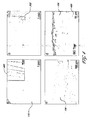
- Figures 4A-D are scanning electron micrographs of one embodiment of carbon nanotubes grown upon a 2-D woven fiber;
- A Low magnification top down view of received 2-D fiber cloth;
- B Low magnification top down view of 2-D fiber cloth illustrating coverage of the cloth with carbon nanotubes;
- C High magnification view of (B);
- D Through-thickness view of (B), illustrating that the carbon nanotubes are oriented approximately perpendicular to the plane of the fiber cloth;
- Figures 5A-B are schematic illustrations of embodiments of mechanical test specimens for measurement of interlaminar fracture toughness and corresponding testing results of embodiments of the 2-D baseline and 3-D nanocomposites illustrating the improvement in interlaminar fracture toughness with through-thickness reinforcement of carbon nanotubes;
- A Double cantilever beam (DCB) test for Mode I fracture toughness;
- B End notched flexure test for Mode II fracture toughness;
- C Load-deflection response of (A);
- D Load-deflection response of (B);
- Figures 6A-B are scanning electron micrographs of fracture surfaces of embodiments of the 2-D baseline composites ( Figure 6A ) and 3-D nanocomposites ( Figure 6B ) illustrating the difference in appearance of the fracture surface upon inclusion of the carbon nanotube reinforcement through the thickness into the 3-D nanocomposite;
- Figures 7A-B are in-plane modulus ( Figure 7A ) and hardness ( Figure 7B ) values of embodiments of the 2-D baseline and 3-D nanocomposites illustrating the improvement in these properties with through-thickness reinforcement of carbon nanotubes;
- Figures 8A-B present the test configuration ( Figure 8A ) and exemplifying data ( Figure 8B ) for mechanical damping tests;
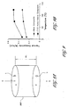
- Figures 9A-B present the test configuration ( Figure 9A ) and experimental measurements of through-thickness thermal conductivity as a function of temperature ( Figure 9B ) for embodiments of the 2-D baseline and 3-D nanocomposites illustrating the improvement in through-thickness thermal conductivity with through-thickness reinforcement of carbon nanotubes;
- Figure 10 is one embodiment of a test sample for measurement of through-thickness electrical conductivity
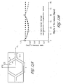
- Figures 11A-B illustrate certain embodiments of analytical and finite element modeling of the mechanical and thermoelastic behavior of carbon nanotubes a function of chirality angles;
- A Periodicity cell utilized in an Asymptotic Harmonization Method (AHM);
- B Comparison of SWNTs as a function of chirality angle using AHM and finite element modeling;
- Figures 12A-B illustrate embodiments of heating schedules for curing (A) and pyrolysis (B) of pre-ceramic polymers utilized to deposit SiC on non-SiC fiber cloths.
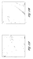
- Figures 13A-D are scanning electron micrographs illustrating top down views of non SiC fiber cloths used as substrates for CVD growth of CNTs without a SiC coating; (A-B) glass fiber; (C-D) carbon fiber; and
- Figures 14A-B are scanning electron micrographs illustrating top down views of non SiC fiber cloths used as substrates for CVD growth of CNTs with a SiC coating.
- FIG. 1 illustrates one embodiment of a laminated 3-D nanocomposite 100.
- the 3-D nanocomposite 100 comprises a reinforcing 3-D reinforcement 102 and a surrounding matrix 104.
- the 3-D reinforcement 102 comprises carbon nanotubes (CNTs) 106 oriented approximately perpendicular to, and interconnected with 2-D woven fiber cloths 110.
- CNTs carbon nanotubes
- the unique properties of the nanotubes 106 also provide through-thickness properties to the 3-D nanocomposite 100, including electrical and thermal conductivity, thermal expansion, and mechanical damping, which are improved over comparable 2-D reinforced composites.
- the improvements in properties provided by the 3-D reinforcement and the through-thickness nanotubes 106 in particular, allow the 3-D nanocomposites 100 to perform multiple functions simultaneously, such as supporting a thermal and mechanical loads through the nanocomposite thickness concurrently or supporting a mechanical or thermal loads while utilizing the through thickness conductivity to monitor the state of damage in the nanocomposite 100.
- Carbon nanotubes are a relatively new configuration of carbon which has been developed.
- a single walled carbon nanotube can be conceptualized as wrapping a one-atom-thick layer of graphite called graphene into a seamless cylinder.
- Most SWNTs have a diameter of close to about 1 nanometer (nm), with a tube length that can be many thousands of times larger. For example, SWNTs with length up to orders of centimeters have been produced.
- a multiple walled carbon nanotube (MWNT) comprises multiple layers of graphite rolled upon themselves to form a tube shape.
- carbon nanotubes possess a relatively low density for a solid, approximately 1.3-1.4 g/cm 3 . This provides CNTs a specific strength which is very high, also making them very attractive for use in composite materials, which are often utilized in applications where weight is a key design consideration. Nanotubes may also be engineered with high thermal and electrical conductivities. As discussed in greater detail with respect to the examples below, the use of CNTs as a through-thickness reinforcement in conjunction with 2-D fiber reinforcements provides the 3-D nanocomposites 100 with mechanical, thermal, and electrical properties that are superior to their two-dimensionally reinforced counterparts.
- a method 200 of manufacturing the 3-D reinforcement and 3D-nanocomposite 100 is schematically illustrated in Figures 2A-2D .
- a 2-D fiber cloth 110 is provided.
- carbon nanotubes 106 are grown on the surface of the 2-D fiber cloths 110, oriented approximately perpendicular to the plane of the fiber cloth 110 to form a 3-D fiber preform 302.
- the 3-D fiber preforms 302 are infiltrated with the polymer matrix 103 to form the individual lamina 112.
- the 3-D nanocomposite 100 is formed from the lamina 112 using generally understood laminate assembly techniques, such as, in non-limiting embodiments, hand lay-up or resin transfer molding.
- Figures 3A-B illustrate one embodiment of the growth of CNTs 106 on the 2-D fiber cloths 110.
- the fiber cloth 110 may comprise 2-D plain-weave fiber cloths 110 of SiC, C, and glass.
- the fiber cloths 110 may comprise satin-weave fiber cloths.
- the satin weave fabrics may comprise 5- or 8-harness satin weave fabrics.
- non-SiC fibers having a coating of SiC, such as C and glass-fiber cloths may also be utilized.
- the use of 2-D fiber cloths 110 with different weave patterns also allows a measure of control over the degree of the alignment of the CNTs 106 in the 3-D reinforcement 102 and the nanocomposite laminate 100 through-thickness direction.
- the degree of CNT alignment substantially perpendicular to the 2-D fiber cloth will increase as the weave-harness number increases, as the cloth will have less undulation and more flat areas. Therefore, more CNTs will be substantially aligned perpendicular to the plane of the fiber cloth.
- the degree of CNT alignment substantially perpendicular with respect to the fiber cloth will decrease as the weave-harness number decreases, as the cloth has more undulation and fewer flat areas.
- 2-D SiC fiber cloths 110 are placed approximately within the middle of a furnace 304, for use as a substrate upon which the nanotubes 106 will grow.
- the 2-D SiC fiber cloths 110 have a width of approximately 1 inch, with lengths varying up to approximately eight inches.
- the as-received 2-D SiC fiber cloths 110 are fabricated from filaments possessing an average diameter of approximately 16 ⁇ m. As illustrated in Figures 3A-B , the 2-D SiC fiber cloth 110 can be oriented either vertically ( Figure 3A ) or horizontally ( Figure 3B ).
- the vertical orientation allows growth of CNTs 106 on both sides of the 2-D fiber cloth 110, while the horizontal orientation allows growth of CNTs 106 on only one side of the 2-D fiber cloth 110.
- 2-D SiC fiber cloths 110 with CNTs 106 grown on both sides may be used as 3-D fiber preforms 302 for fabrication of multi-layer 3-D nanocomposites 100, while cloths with CNTs 106 grown on one side may be utilized as 3-D fiber preforms 302 in dual layer 3-D nanocomposites 100.
- nanotubes are grown on the 2-D fiber cloths 110 by chemical vapor deposition (CVD) based on Andrews et al., "Continuous Production of Aligned Carbon Nanotubes: A Step Closer to Commercial Realization," Chem. Phys. Lett., 303, 467-474 (1999 ), the entirety of which is hereby incorporated by reference.
- a quartz tube 306 having an inner diameter of approximately two inches is housed in a horizontal furnace 304 for use as a reaction chamber 306.
- Ferrocene and xylene are utilized as a catalyst precursor and carbon source, respectively, as this combination is known to produce nanotubes which are aligned approximately perpendicular to a substrate surface, such as the 2-D fiber cloth 110.
- Ferrocene powder is dissolved into the xylene in a ratio of approximately 0.1 mg ferrocene to 10 ml xylene, forming a brown colored precursor solution 310.
- the furnace 304 is heated and maintained at approximately 800°C and the ferrocene/xylene precursor solution 310 is injected into the furnace 304 through a syringe pump at a constant speed, approximately 0.1-0.5 ml/min.
- Argon gas is flowed at approximately 40 s.c.c.m to carry the solution into a steel bottle (not shown) which is pre-heated within the range of about 150 to 200 °C, allowing the precursor solution 310 to vaporize before entering the furnace 304 containing the 2-D SiC fiber cloth 110.
- the precursor solution 310 decomposes into small Fe particles containing dissolved carbon that attach to the surface of the 2-D SiC fiber cloth 110.
- the nanotubes grow as carbon clusters from the carbon which precipitates out of the Fe particles.
- the length of the nanotubes 106 is varied in the range of tens to hundreds of micrometers by adjusting the CVD reaction time, from about 10 minutes to one hour.
- nanotubes of about 1 to 500 ⁇ m in length more preferably about 60 ⁇ m, possessing diameters in the range of about 10 to 100 nm more preferably about 30-50 nm, are grown after 40 minutes growth, providing sufficient length for mechanical interlocking, as discussed in greater detail below.
- the CVD nanotube growth described above allows 3-D fiber preforms 302 having large areas to be easily produced. Furthermore, the size of the 3-D fiber preforms 302 are only limited by the size of the furnace chamber, allowing 3-D fiber preforms 302 of arbitrary size to be produced. For example, in one embodiment, a 3-D fiber preform 302 having dimensions of approximately 13 cm x 4 cm are prepared using this method, although preforms 302 of greater or lesser size are also possible.
- the nanotubes grown on the surface of the 2-D SiC fiber cloth 110 are aligned approximately perpendicular to the plane of the 2-D woven fabric 110 and cover the surface of the fiber cloth 110 approximately uniformly.
- Figures 4A-D illustrate top down and cross-sectional micrographs of the 2-D SiC fiber cloth 110 before and after growth of the nanotubes on the surface of the fiber cloth 110.
- Figure 4A presents the as-received fiber cloth 110, where the individual filaments 400 are apparent.
- Figure 4B illustrates a low magnification, top down view of the 3-D fiber preform 302, in which CNTs 106 are grown on the surface of the 2-D fiber cloth 110.
- Figure 4B the CNTs 106 substantially cover the entire surface of the 2-D fiber cloth after completion of the CVD process, giving the fiber cloth a coarse appearance compared to Figure 4A.
- Figure 4C presents a higher magnification view of Figure 4B , magnified approximately 10x from Figure 4B , further illustrating CNTs 106 grown on the surface of the 2-D SiC fiber cloth 110. This view clearly illustrates that the CNTs 106 are grown approximately uniformly on the filaments 400, as all the exposed filaments 400 on the surface of the fiber cloth 110 are covered by CNTs 106.
- Figure 4D presents a side view of the CNTs grown on a filament 400 of the 2-D fiber cloth 110, illustrating that the CNTs grown on the 2-D fiber cloth 110 are aligned approximately perpendicular to the plane of the fiber cloth 110 in a linear array.
- the 3D-nanocomposite is fabricated from the 3D-fiber preforms 302 formed as described above with respect to Figure 2 .
- a plurality of 3-D fiber preforms 302 are stacked, infiltrated with the matrix material or a matrix material precursor, and subsequently cured.
- the matrix material may be varied, as dictated by the application.
- the 3-D fiber preform 302 may be infiltrated with a polymer.
- the polymer may comprise a high temperature epoxy based on diglycidyl ether of bisphenol A (DGEBPA) and alkylglycidyl ether (AE).
- DGEBPA diglycidyl ether of bisphenol A
- AE alkylglycidyl ether
- the polymer may comprise a pre-ceramic polymer such as KiON CERASET ® .
- the viscosity of the matrix designed to be substantially low enough so as to permit substantial wetting of the 3-D fibers preforms 302 with the matrix polymer.
- the 3-D fiber preforms 302 are soaked in a DGEBPA-AE epoxy resin bath for approximately 10 minutes to allow infiltration of the epoxy into the 3-D fiber preform 302. Subsequently, the infiltrated lamina 112 were stacked individually and hand rolled to substantially remove excess resin and achieve compaction as generally understood in the context of conventional wet lay-up and/or prepreg hand lay-up processes. In the next step, stacked laminated structure is subsequently cured in an autoclave at a maximum of 150° C for one hour to yield the 3-D nanocomposite 100 with the through thickness nanotubes 106 functioning as the core.
- a two layered sandwich composite structure may be formed, where two SiC cloths with CNTs grown on one side reinforce a high temperature epoxy matrix having weight fractions of the matrix, SiC fiber cloth, and CNTs of 35%, 63%, and 2%, respectively.
- nanomaterials may be introduced into the polymer prior to infiltration into the 3-D fiber preform 302 in order to provide dispersion strengthening of the 3-D nanocomposite 100.
- the nanomaterials may comprise nanoparticles or CNTs, as disclosed in co-pending patent application entitled, "Polymer Matrix Composites With Nano-Scale Reinforcements", and U.S Provisional Patent Application Numbers 60/753,006 filed on December 12, 2005 , 60/753,155 filed on December 20, 2005 , and 60/753,496 filed on December 22, 2005 entitled SUPER PERFORMING CNT/EPOXY RESIN, the entirety of each of which is hereby incorporated by reference.
- low weight fractions of nanoparticles such as TiO 2 , SiC, Y 2 O 3 , ZnO, and C, or carbon nanotubes comprising SWNTs, are substantially uniformly distributed within the matrix polymer using a magnetic stirring technique.
- these nanomaterials are dispersed within the matrix such that they are substantially disconnected from the woven fiber cloth.
- the degree of dispersion and efficacy of the nanomaterial reinforcement may be adjusted. Adjustments may comprise, but are not limited to, variation of the nanotube diameter/length, nanoparticle size, and the weight percentage of either nanotubes or nanoparticles.
- the addition of the discrete nanotube or nanoparticle reinforcements within the matrix allows further adjustment of the properties of the 3-D nanocomposites so as to tailor the nanocomposite 100 as necessary to meet the demands of particular applications.
- the adhesion properties of the CNTs to the 2-D fiber cloth may be also varied using an annealing technique in order to vary the properties of the resultant 3-D nanocomposite 100.
- the adhesion strength of the CNT-fiber interface may be strengthened by subjecting the 3-D fiber preform 302 to a heat treatment of approximately 950°C for approximately 1-6 hours in an argon atmosphere.
- a heat treatment of 950°C for approximately six hours has been observed to provide a nearly two-fold increase in adhesion strength of CNT nanobrushes on SiC fiber, from about 0.1 to 0.3 MPa to approximately 0.5 MPa. Therefore high-temperature annealing is an additional processing step which may optionally be used to enhance the adhesion strength between nanotubes and SiC fibers and thus in turn, influence the nanocomposite 100 properties.
- testing is performed on 3-D nanocomposites and their 2-D counterparts to illustrate the property improvements which may be achieved through embodiments of the 3-D nanocomposite 100.
- in-plane and interlaminar mechanical properties, mechanical damping, thermoelastic response, and thermal and electrical conductivities are examined.
- the 3-D nanocomposites 100 tested are laminates formed as described above, using a 3-D fiber preform 302 of SiC plain-weave fiber cloths having CVD-grown MWCNTs extending approximately perpendicular to the plane of the SiC fiber cloth and a matrix of DGEBPA-AE.
- the nanocomposites further possess weight fractions of the matrix, SiC fiber cloth, and CNTs of approximately 35%, 63%, and 2%, respectively.
- 2-D baseline composites were similarly formed without the MWCNT reinforcement.
- Examples 1-4 illustrate the advantages of using of 3-D nanocomposites over their 2-D counterparts to increase the delamination resistance of the composite.
- One of the most commonly observed damage modes in laminated composites is the separation of adjacent plies, or delamination. Delamination in laminated composites may arise from one of the many events, including low velocity impacts, fatigue loadings, eccentricities in the load path, or by geometric and structural discontinuities, such as holes, edges, or ply drops, that act as stress raisers within the area adjacent to the discontinuity.
- interlaminar fracture toughness testing is performed to determine interlaminar fracture toughness for two different modes of loading, Mode I, an opening mode, and Mode II, a sliding mode.
- Mode I fracture toughness testing is performed according to ASTM standard D 5528-94a, "Test Method for Mode I Interlaminar Fracture Toughness of Unidirectional Fiber-Reinforced Polymer Matrix Composites.”
- the specimen geometry for this testing, a double cantilever beam 500 (DCB), is illustrated in Figure 5A .
- the DCB specimen 500 is a rectangular beam having length, L, of approximately 120 mm and a width, W, of approximately 20 mm.
- An initial crack 502 of length a o is introduced between the lamina 112 by insertion of a Teflon TM film approximately 12.5 ⁇ m thick.
- the lamina 112 are pulled apart with an applied force, F, using an Instron 4206 testing machine and the load and displacements are recorded.
- Mode II interlaminar fracture toughness testing is performed according to the method of Adams, et al. in "Experimental Characterization of Advanced composite Materials," 3rd Ed .
- the test is conducted using an end notched flexure (ENF) specimen 506, as illustrated in Figure 5B .
- ENF specimens 506 possess the same dimensions and crack length as the DCB specimens 500 discussed above.
- the lamina 112 are slid past one another by loading the ENF specimen in flexure, compressively loading of the ENF specimen 506 at approximately the center of the length with a force F while supporting the specimen 506 ends.
- Testing is conducted using an Instron 4206 testing machine and the load and displacements are recorded.
- the crack 502 is monitored to determine the critical compressive force, F c , and displacement, ⁇ c, at which the crack 502 starts to propagate along the length, L, of the DCB specimen 506.
- Equation 2 the G IIC is calculated for both the 3-D nanocomposites and comparable 2-D composites and the results are presented in Table 1 below. It should be noted that Equation 2 is not compliance corrected, as it is used for comparison purposes between the 2-D baseline composite and 3-D nanocomposite.
- Equations 1 and 2 the G IC and G IIC are calculated for both the 3-D nanocomposites and comparable 2-D composites. Average values for three test specimens are presented in Table 1 below. Table 1- G IC of 2-D baseline composites and 3-D nanocomposites. Example Materials Mode G IC (kJ/m 2 ) % Change From Baseline 1C 2-D Baseline composite I 0.95 N/A 2 3-D Nanocomposite I 4.26 450 3C 2-D Baseline composite II 91e-3 N/A 4 3-D Nanocomposite II 140e-3 54
- the 3-D nanocomposite demonstrates a G IC of approximately 4.26 kJ/m 2 , compared to that measured for the 2-D baseline composites, approximately 0.95 kJ/m 2 . These results represent an over four-fold improvement in the Mode I fracture toughness of the 3-D nanocomposite over the 2-D baseline composite.
- the 3-D nanocomposite demonstrates a G IIC of approximately 140 J/m 2 , compared to the 2-D baseline composite value of approximately 91 J/m 2 . These results represent an improvement of over fifty percent in the Mode II fracture toughness of the 3-D nanocomposite over the 2-D baseline composite.
- the improved toughness of the 3-D nanocomposite is provided by the through-thickness nanotubes 106 can also be seen in SEM micrographs of the fracture surfaces of the two composites between adjacent lamina of the 2-D baseline composite ( Figure 6A ) and the 3-D nanocomposite ( Figure 6B ).
- the 2-D baseline composite exhibits a relatively smooth fracture surface 600 within the matrix 103.
- the 3-D nanocomposite 100 exhibits a plurality of nanotubes 106 which extend outward from the fracture surface 602 which are embedded within the matrix 103.
- nanotubes 106 from adjacent lamina interlock during fabrication of the nanocomposite, providing a mechanical interconnection between the 3-D fiber preform of the adjacent lamina. This interlocking increases the resistance to lamina separation, and raises the interlaminar toughness in both Mode I and Mode II loadings.
- Examples 5-6 illustrate the effect of CNTs on the in-plane mechanical properties of 2-D baseline composites and 3-D nanocomposites.
- the in-plane tensile strength, elastic modulus, and flexural toughness of the two composite systems are measured by 3-point, in-plane flexure loading based upon ASTM Standard D790-00, titled, "Standard Test Methods for Flexural Properties of Unreinforced and Reinforced Plastics and Electrical Insulating Materials.” Average values for three test specimens are reported in Table 2 below, with the percent change in the 3-D nanocomposite property values over the 2-D baseline composite in parentheses. Table 2 - G IC of 2-D baseline composites and 3-D nanocomposites.
- Examples 5-6 demonstrate that the through-thickness CNTs may provide significantly improved in-plane mechanical properties over their 2-D counterparts, rather than the diminishment of the mechanical properties, as observed when adding through-thickness reinforcements to other composite systems.
- Flexural strength increases over two-fold, from about 62.1 MPa to approximately 150.1 MPa.
- flexural toughness increases over five-fold, from approximately 5.8 N mm to approximately 30.4 N mm. Flexural modulus is found to remain approximately unchanged, increasing approximately five percent from 23.1 GPa to 24.3 GPa.
- Example 7-8 Indentation Hardness and Modulus
- Example 7-8 illustrates the spatial homogeneity of the properties of 3-D nanocomposites.
- a concern with the introduction of the through-thickness reinforcement is the uniformity of properties arising from the reinforcement. That is to say, the reinforcement may cause spatial variation in local mechanical properties. These variations are not apparent in macro-scale testing, in which relatively large volumes of the composite are sampled, providing an average property value. Thus, nanoindentation is performed in order to measure hardness and modulus through the thickness of the composite.
- Nanoindentation of the 2-D baseline composite and the 3-D nanocomposite is performed using the MTS Nanolndenter TM XP (MTS Nano Instruments, Oak Ridge, Tennessee). The nanoindentation is conducted according to procedure outlined in the Product Data Sheet for the Nanolndente TM . Samples arc cut and polished flat using an approximately 0.5 ⁇ m grit. Samples are mounted for stability to an aluminum stub using epoxy. In the indentation test, an area of the nanocomposite is selected, a hard tip is pressed into the sample at a known load for a predetermined time, and the residual area of the indent is determined. Load and displacement are continuously recorded during testing. The hardness is proportional to the applied load divided by the area of the indent.
- the loading increment is maintained at approximately 5% of the present load per second.
- the maximum indentation load was varied over the range of approximately 0.115 - 2.5 ⁇ N to provide measurements at through-thickness depths up to approximately 1 ⁇ m. Ten indentations were carried out at each depth and the average result is reported. The results of these tests are illustrated in Figures 7A-B , with error bars representing one standard deviation of the mean.
- Examples 7-8 demonstrate that the spatial variation in the hardness and modulus of the 3-D nanocomposite is comparable to the 2-D baseline composite.
- the elastic modulus and hardness of the 3-D nanocomposite follow approximately the same trend as the 2-D baseline composites, indicating that the spatial variation of through-thickness properties in the nanocomposite is comparable to the baseline.
- the modulus is of the 3D nanocomposite is slightly elevated over that of the 2-D baseline composite, approximately 12-30%. This result further reinforces the results of in-plane testing demonstrating that the elastic modulus of the 3-D nanocomposite is modestly greater than the elastic modulus of the 2-D baseline composite.
- Examples 9-10 illustrate the effect of throug-thickness CNTs on the mechanical damping properties of 2-D baseline composites and 3-D nanocomposites.
- Mechanical damping is the dissipation of vibrational energy under cyclic loading. Greater damping in a structure can therefore reduce the amplitude of vibrations imposed by an applied load, improving the fatigue life of a system.
- the fact that CNTs undergo high frequency deformations qualifies them as a strong candidate for structural damping applications.
- the natural frequencies and damping of the 3-D nanocomposite 100 are measured and compared to those of their 2-D composite counterparts.
- the damping test specimens 800 are generally rectangular beams which are fixed in place at one end, as shown in Fig. 8A .
- the damping specimens 800 possess length, L, width W, and thickness, T, of approximately 21.65mm x 1.25mm x 25.4mm, respectively.
- the free end of the damping specimen 800 is initially moved to a predetermined distance and then released, causing free vibration of the damping specimen 800.
- the displacement at the free end of the damping specimen 800 is monitored by a laser displacement sensor 802, recorded by a laser displacement controller 804, and transformed into frequency domain with a dynamic signal analyzer 806.
- f m the frequency at which the measured vibrational amplitude (A) is maximum
- f 1 and f 2 are the two frequencies at which the amplitude is 0.707 times of its maximum
- ⁇ f is the difference between f 2 and f 1 , also called half-power bandwidth.
- the damping ratio represents the ratio of actual damping, C, to a critical damping, C c , that can prevent vibration, even at resonant frequency. Therefore, the closer the damping factor is to 1, the higher the degree of damping possessed by a structure. The average results of three tests are reported below in Table 3. Table 3 - Mechanical damping properties of 2-D baseline composites and 3-D nanocomposites.
- Thermal conductivity is a material property which provides a measure of the rate at which heat is transferred through the material by conduction.
- Figure 9A thermal conductivity
- K Q A ⁇ ⁇ ⁇ T ⁇ ⁇ L
- the tests are conducted using Anter Corporation's UnithemTM Model 2022 Thermal Conductivity Measuring System in accordance with ASTM Standard E1530, "Guarded Heat Flow Meter Test Method".
- the sample is held under a uniform compressive load between two polished surfaces (not shown), each at a different temperature, where the lower surface is part of a calibrated heat flow transducer.
- Heat, Q flows from the upper surface, through the sample 900, to the lower surface, establishing an axial temperature gradient in the sample.
- ⁇ T across the sample 900 is measured with temperature sensors in the highly conductive metal surface layers on either side of the sample 900 and the heat flow is measured with the heat flow transducer.
- the temperature gradient, ⁇ T, the sample thickness, ⁇ L, and the sample cross-sectional area, A are then used to calculate the thermal conductivity from Equation 6.
- Figure 9B illustrates the thermal conductivity of the 2-D baseline composite and 3-D nanocomposite at temperatures of approximately 8, 75, and 125°C.
- the data demonstrate consistent improvements in the thermal conductivity of the 3-D nanocomposite compared to the 2-D baseline composite over the complete range of temperatures probed, from approximately 30% or more at temperatures of around 10°C to approximately 50% or more at temperatures of approximately 125°C.
- Examples 13-14 illustrate the effect of CNTs on the through-thickness thermal expansion of 2-D baseline composites and 3-D nanocomposites.
- the thermoelastic behavior of composites plays a major role in their dimensional stability and tolerances, particularly under severe temperature changes.
- large dimensional changes can give rise to large thermal stresses, which in turn can lead to cracking and premature failure of the composite.
- low thermal expansion is particularly important for structures that are sensitive to shape changes and operate under tight tolerances, such as those used in space optics, e.g., space telescopes and satellite dishes.
- CTE Coefficient of Thermal Expansion
- the through-the-thickness measurements are made with a Michelson laser interferometer measurement system based on ASTM Standard E289-04, "Standard Test Method for Linear thermal Expansion of Rigid Solids with Interferometry" and performed under vacuum.
- Test specimens are heated to approximately 150°C and held at temperature until their dimensions stabilize. Measurements of the specimen dimensions are taken as the specimen temperature is cycled between the temperatures of approximately 150°C to 0°C for at least 1 full temperature cycle. Further, the specimen thickness change and temperature are continuously recorded during the tests.
- Examples 13-14 illustrate the improved dimensional stability provided to the composite by the through-thickness nanotube reinforcement.
- the average CTE is reduced by approximately 62%, from about 123.9 p.p.m/°C in the 2-D baseline composite, to about 47.3 p.p.m/°C in the 3-D nanocomposite.
- Examples 15-16 illustrate the effect of CNTs on the through-thickness electrical conductivity of 2-D baseline composites and 3-D nanocomposites.
- a two probe measuring method where the resistance of an electrical conductivity test specimen 1000 is measured at a number of predetermined locations of the specimen, Figure 10 , to determine its electrical conductivity. Tests are performed by polishing the upper and lower surfaces of the test specimen 1000 and depositing gold layers 1002 on the predetermined locations to form an electrical contact, as illustrated in Figure 10 . The average of three tests for each composite are reported in Table 5 below. Table 5 - Through-thickness electrical conductivity of 2-D baseline composite and the 3-D nanocomposite.
- the average electrical conductivity of the 3-D nanocomposites is significantly higher than that of the 2-D composite.
- the electrical conductivity of the 3-D nanocomposite was approximately 0.408 S/cm, while that of the 2-D baseline composite was approximately 0.075e-6 S/cm, an increase of over million-fold.
- the 2-D baseline composite is substantially non-conducting through the thickness but the 3-D nanocomposite is substantially conducting.
- the relatively high electrical conductivity of the 3-D nanocomposite in the through-thickness direction further expands the capability of the nanocomposite.
- the 3-D nanocomposite may be configured to act as a sensor which monitors the development of cracks and crack growth in the 3-D nanocomposites, providing a relative measure of the "health" of the nanocomposite.
- electrical connections are attached along a notched composite, such as the DCB and ENF specimens described above with respect to Figure 5 . Specimens are loaded and the resulting crack growth measured using any combination of optical, mechanical, and crack gauge techniques as generally understood in the art for the DCB and ENF loadings. Concurrent, continuous measurement of the electrical conductivity thus provides electrical conductivity as a function of crack growth and delamination. With this calibration the electrical conductivity of 3-D nanocomposites deployed in the field may be measured to determine the extent of any cracking within the composite.
- this health monitoring capability significantly improves the safety of using the 3-D nanocomposites.
- Monitoring the extent of cracking by electrical conductivity is non-destructive, allowing technicians to establish the extent of cracking without damaging or destroying the composite.
- monitoring cracks in this manner is superior to optical observations, as it may detect sub-surface cracking as well as fine cracks which are not apparent through the naked eye or light microscopy.
- 3-D nanocomposite materials may be deployed in-service with the health monitoring configured to provide real-time measurements of the extent of cracking, allowing technicians to replace damaged 3-D nanocomposites while within safety tolerances.
- Example 17 illustrates analytical and finite element modeling of the thermomechanical behavior of individual CNTs.
- the analytical and computational methods discussed in detail below may substantiate the results from the experiments of the nanocomposite specimens discussed in the examples above.
- thermoelastic behavior of carbon nanotubes are examined as a function of chirality angles, as illustrated in Figures 11A-B .
- Asymptotic Homogenization Method (AHM) is utilized for analytical study and finite element analysis (FEA) is utilized as a numerical approach.
- FEA finite element analysis
- the thermomechanical behavior of individual CNTs are examined.
- a periodicity cell of the graphene sheet forming SWNT is considered, as illustrated in Figure 11A .
- AHM predicts substantially no chirality dependence in the axial Young's modulus of a carbon SWNT. This result which may be attributed to the volume averaging and homogenization technique that has been performed in this method, however, the model very well succeeds in developing the structural parameters dependencies of the modulus.
- Finite element analyses of the carbon networks with different structures, such as zigzag, armchair, and chiral structures predict a slight dependency of the axial Young's modulus of SWNT on its chirality angle ( Figure 11B ).
- the finite element analysis further predicts that the zigzag SWNT has the highest axial modulus and the armchair nanotube has the lowest modulus.
- the chiral SWNTs lie in between these two limits, with a trend of decrease in modulus with increasing chirality from zigzag to armchair configurations.
- these results allow prediction of the effective properties of 3-D nanocomposites. Furthermore, the effects of adhesion strength of the CNT-fiber interface on the properties of the 3-D nanocomposites may be predicted.
- Examples 18 and 19 investigate the effects of SiC coatings on non-SiC fiber cloths used as substrates for CVD CNT growth. Growth of CNTs on both uncoated glass fiber cloths and coated carbon fiber cloths are performed and examined to assess the influence of the SiC coating on the growth.
- the SiC coatings are provided through use of a pre-ceramic polymer.
- Pre-ceramic polymers can be comprised of an organo-metallic polymer which, after a pyrolysis step, is transformed into ceramic materials.
- the KiON CERASET ® family of pre-ceramic polymers are liquid compositions which may provide SiC, SiN, and silicon carboxide, depending on gas environment and the parameters employed during pyrolysis.
- carbon fiber cloths are coated with a layer of KiON CERASET ® and pyrolyzed in an inert nitrogen environment to provide a coating of SiC over approximately the surface of the carbon fiber cloths.
- the diameter of the filaments within the fiber cloth is approximately 16 microns
- the thickness of the SiC coating is on the order of the fiber diameter, within the range of approximately 10 to 20 microns.
- the SiC coating is provided on carbon fiber cloths in the following manner.
- the polymer composition is applied to the fiber cloths.
- a pre-ceramic polymer composition is prepared by mixing KiON CERASET ® with approximately 2 wt % dicumyl peroxide, a free radical initiator, on the basis of the total weight of the composition.
- the carbon fiber cloths meanwhile, are laid upon a tooling surface, such as an aluminum plate.
- the composition is applied to the fiber cloths by brushing, which provides control over the uniformity, wetting, and thickness of the coating on the woven fiber cloths.
- alternative coating methods known in the art including but not limited to spraying and dipping, may also utilized to coat the fiber cloths with the pre-ceramic composition in alternative embodiments.
- the pre-ceramic polymer is converted to a ceramic through curing and pyrolysis operations.
- the ceramic formed comprises SiC, although it may be understood that the pre-ceramic polymer may be pyrolyzed to yield other ceramics by modifying the procedure discussed below as understood by those of skill in the art.
- the tooling surface containing the treated carbon fiber cloths is placed within a mechanical convection oven and subjected to a curing operation according to the manufacturer's cure cycle.
- a curing operation is illustrated in Figure 12A , which is performed under approximately atmospheric pressure.
- the treated cloths are heated from approximately room temperature (22°C) to a target temperature of approximately 200°C.
- Heating is performed over the period of about one hour at a constant heating rate of approximately 2.9°C/min at approximately atmospheric pressure.. Upon reaching the approximately 200°C target temperature, this temperature is maintained for approximately one hour. Following the heat treatment at the target temperature, the fiber cloths are cooled from approximately 200°C to approximately 75°C at a rate of about 2.1°C for approximately one hour. Subsequently, the oven is turned off to allow the fiber cloth to cool down to approximately room temperature by natural convection. This cure substantially converts the pre-ceramic polymer composition to a solid, cross-linked polymer through a vinyl cross-linking mechanism.
- the carbon fiber cloths are pyrolyzed to convert the cross-linked polymer into SiC.
- the carbon fiber cloths are removed from the convection oven and placed within a tube furnace containing a nitrogen environment in which the nitrogen flows at a rate of approximately 150 CC/min.
- the pyrolysis heat treatment is illustrated in Figure 12B .
- the fiber cloth samples are heated from approximately room temperature to about 100°C at a heating rate of approximately 2°C /min, maintained at about 100°C for approximately 2 hours, heated from about 100°C to about 700°C at a rate of approximately 10°C /min, maintained at about 700°C for approximately one hour, heated from approximately 700°C to approximately 1000°C at a rate of about 5°C/min, maintained at about 1000°C for approximately one hour.
- the furnace is then allowed to cool down from about 1000°C to approximately 250°C at a rate of approximately 3°C/min under the nitrogen gas flow.
- the fiber cloths are then cooled down to room temperature by natural convection and removed from the tube furnace. Following this procedure, the carbon fiber cloths possess a layer of SiC on their surface having a thickness in the range of approximately 10-20 um.
- the precursor solution exiting the capillary is immediately vaporized and swept into the reaction zone of the furnace by a flow of argon gas mixed with approximately 10% hydrogen.
- the furnace temperature, ferrocene-xylene feed rate, total reaction time, and argon sweep gas flow rate were adjusted to about 770°C, about 0.125 CC/min, approximately 1 hour, and approximately 60 CC/min, respectively, for growing the aligned MWCNTs on the fibers and their cloth.
- the pre-heater and the furnace are allowed to cool to room temperature in flowing argon gas environment.
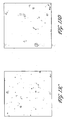
- Figures 13A-B illustrate scanning electron micrographs of the glass fiber cloths after being subjected to the CVD CNT growth process discussed above, while Figures 13C-D illustrate the same for carbon fiber cloths. Examining the fiber cloths at both low magnification ( Figure 13A, C ) and higher magnification ( Figures 13B, D ), the bare fiber cloth is present, with substantially no nanotube growth observed. In contrast, the coated carbon fibers demonstrate significant CNT growth, as illustrated in the top down micrograph of Figure 14A . Similar to the CNTs grown upon SiC fibers, the CNTs grown on the SiC coated carbon fibers exhibit nanotubes which substantially cover the surface of the fiber cloth, approximately uniformly, giving the fiber cloth a coarse appearance.
Landscapes
- Chemical & Material Sciences (AREA)
- Engineering & Computer Science (AREA)
- Materials Engineering (AREA)
- Ceramic Engineering (AREA)
- Manufacturing & Machinery (AREA)
- Organic Chemistry (AREA)
- Structural Engineering (AREA)
- Composite Materials (AREA)
- Mechanical Engineering (AREA)
- Nanotechnology (AREA)
- Medicinal Chemistry (AREA)
- Health & Medical Sciences (AREA)
- Polymers & Plastics (AREA)
- Chemical Kinetics & Catalysis (AREA)
- Inorganic Chemistry (AREA)
- Textile Engineering (AREA)
- Physics & Mathematics (AREA)
- Crystallography & Structural Chemistry (AREA)
- General Physics & Mathematics (AREA)
- Condensed Matter Physics & Semiconductors (AREA)
- Reinforced Plastic Materials (AREA)
- Laminated Bodies (AREA)
- Carbon And Carbon Compounds (AREA)
- Sliding-Contact Bearings (AREA)
- Manufacture Of Alloys Or Alloy Compounds (AREA)
- Woven Fabrics (AREA)
- Treatments For Attaching Organic Compounds To Fibrous Goods (AREA)
Claims (15)
- Dreidimensional verstärktes Verbundlaminat, das umfasst:ein Matrixmaterial;eine im Wesentlichen innerhalb der Matrix positionierte Verstärkung, die ein Webfasertuch und Kohlenstoff-Nanoröhrchen, die mit der Webfaser verbunden sind, wobei sie von einer durch das Webtuch definierten Oberfläche nach außen verlaufen, umfasst;wobei das Webfasertuch wenigstens auf der Oberfläche des Webfasertuchs SiC-Fasern und/oder Fasern mit einer Schicht eines SiC-Belags umfasst.
- Verbundlaminat gemäß Anspruch 1, bei dem die Matrix ein Hochtemperaturepoxid auf der Grundlage eines Diglycidylethers von Bisphenol A und eines Alkylglycidylethers, eine Keramik auf der Grundlage eines metallorganischen Polymers oder einen Polyester umfasst.
- Verbundlaminat gemäß Anspruch 1, das ferner Nanopartikel oder Kohlenstoff-Nanoröhrchen umfasst, die innerhalb der Matrix dispergiert sind.
- Verbundlaminat gemäß Anspruch 1, bei demdie Kohlenstoff-Nanoröhrchen senkrecht zur Oberfläche des Fasertuchs ausgerichtet sind;die Kohlenstoff-Nanoröhrchen benachbarter Dünnschichten im Wesentlichem mechanisch miteinander verzahnt sind; unddie Kohlenstoff-Nanoröhrchen mehrwandige Kohlenstoff-Nanoröhrchen sind.
- Verbundlaminat gemäß Anspruch 1, bei dem das Webfasertuch eine 2D-Geometrie aufweist.
- Verbundlaminat gemäß Anspruch 1, bei dem das Webfasertuch ein 2D-Fasertuch umfasst, das ein C- oder Glasfasertuch umfasst, und ferner wenigstens auf der Oberfläche des Tuchs eine Schicht aus SiC umfasst.
- Textilverstärkung, die umfasst;ein Webfasertuch; undKohlenstoff-Nanoröhrchen, die mit dem Webfasertuch verbunden sind, wobei die Nanoröhrchen von dem Webfasertuch nach außen verlaufen und in der Richtung nach außen orientiert bleiben;wobei das Webfasertuch wenigstens auf der Oberfläche des Fasertuchs SiC-Fasern und/oder Fasern mit einer Schicht eines SiC-Belags umfasst.
- Textilverstärkung gemäß Anspruch 7, die ferner mehrere Webfasertücher mit Kohlenstoff-Nanoröhrchen, die mit den Webfasertüchern verbunden sind, umfasst, wobei die Nanoröhrchen senkrecht zur Oberfläche der Webfasertücher verlaufen, wobei die Nanoröhrchen von benachbarten Fasertüchern miteinander verbunden sind.
- Textilverstärkung gemäß Anspruch 7, bei der das Webfasertuch Kohlenstoff-oder Glasfasern umfasst, die mit SiC beschichtet sind.
- Verfahren zur Herstellung eines dreidimensional verstärkten Verbundlaminats, wobei das Verfahren umfasst:Bereitstellen eines zweidimensionalen Webfasertuchs, das wenigstens auf der Oberfläche des Fasertuchs SiC-Fasern und/oder Fasern mit einer Schicht eines SiC-Belags umfasst;Aufwachsenlassen von Kohlenstoff-Nanoröhrchen auf einer Oberfläche des Webfasertuchs in der Weise, dass ein dreidimensionaler Faservorformling gebildet wird;erhebliches Tränken des dreidimensionalen Faservorformlings mit einem Matrixmaterial zum Bilden einer dreidimensionalen Verbunddünnschicht;Zusammensetzen mehrerer dreidimensionaler Verbunddünnschichten in der Weise, dass die Nanoröhrchen im Wesentlichen zwischen den Dünnschichten positioniert werden;Aushärten der zusammengesetzten Dünnschichten.
- Verfahren gemäß Anspruch 10, bei dem das Webfasertuch ein C- oder Glasfasertuch umfasst und ferner wenigstens auf der Oberfläche des Tuchs eine Schicht aus SiC umfasst.
- Verfahren gemäß Anspruch 10, bei dem die Kohlenstoff-Nanoröhrchen durch chemischen Dampfniederschlag eines Nanoröhrchens und einer Katalysatorvorläuferlösung auf der Oberfläche des Webfasertuchs aufwachsen gelassen werden.
- Verfahren gemäß Anspruch 10, bei dem:Kohlenstoff-Nanoröhrchen auf beiden Seiten des Webfasertuchs aufwachsen gelassen werden;die Kohlenstoff-Nanoröhrchen senkrecht zur Oberfläche des Fasertuchs ausgerichtet werden; oderdie Kohlenstoff-Nanoröhrchen benachbarter Dünnschichten im Wesentlichem mechanisch miteinander verzahnt werden.
- Verfahren gemäß Anspruch 10, bei dem die Matrix ein Hochtemperaturepoxid auf der Grundlage eines Diglycidylethers von Bisphenol A und eines Alkylglycidylethers, eine Keramik auf der Grundlage eines metallorganischen Polymers oder einen Polyester umfasst.
- Verfahren gemäß Anspruch 10, bei dem die Dünnschichten durch Handauflegen oder durch ein Harzinjektionsverfahren zusammengesetzt werden.
Priority Applications (1)
| Application Number | Priority Date | Filing Date | Title |
|---|---|---|---|
| PL06851923T PL1966286T3 (pl) | 2005-11-28 | 2006-11-27 | Trójwymiarowo wzmocnione wielofunkcyjne nanokompozyty |
Applications Claiming Priority (3)
| Application Number | Priority Date | Filing Date | Title |
|---|---|---|---|
| US74046105P | 2005-11-28 | 2005-11-28 | |
| US11/523,731 US8148276B2 (en) | 2005-11-28 | 2006-09-19 | Three-dimensionally reinforced multifunctional nanocomposites |
| PCT/US2006/045418 WO2008054409A2 (en) | 2005-11-28 | 2006-11-27 | Three-dimensionally reinforced multifunctional nanocomposites |
Publications (2)
| Publication Number | Publication Date |
|---|---|
| EP1966286A2 EP1966286A2 (de) | 2008-09-10 |
| EP1966286B1 true EP1966286B1 (de) | 2009-09-30 |
Family
ID=38119398
Family Applications (1)
| Application Number | Title | Priority Date | Filing Date |
|---|---|---|---|
| EP20060851923 Not-in-force EP1966286B1 (de) | 2005-11-28 | 2006-11-27 | Dreidimensional verstärkte multifunktionelle nanozusammensetzungen |
Country Status (16)
| Country | Link |
|---|---|
| US (1) | US8148276B2 (de) |
| EP (1) | EP1966286B1 (de) |
| JP (1) | JP5037518B2 (de) |
| KR (1) | KR101316797B1 (de) |
| CN (1) | CN101365740B (de) |
| AT (1) | ATE444329T1 (de) |
| AU (1) | AU2006350255B2 (de) |
| CA (1) | CA2632202C (de) |
| DE (1) | DE602006009559D1 (de) |
| DK (1) | DK1966286T3 (de) |
| ES (1) | ES2334165T3 (de) |
| MX (1) | MX2008006854A (de) |
| MY (1) | MY143396A (de) |
| PL (1) | PL1966286T3 (de) |
| RU (1) | RU2423394C2 (de) |
| WO (1) | WO2008054409A2 (de) |
Cited By (2)
| Publication number | Priority date | Publication date | Assignee | Title |
|---|---|---|---|---|
| CN102219203A (zh) * | 2011-04-15 | 2011-10-19 | 清华大学 | 一种用于复合增强的三维纳米碳材料及其制备方法 |
| US11768193B2 (en) | 2019-12-20 | 2023-09-26 | The Research Foundation For The State University Of New York | System and method for characterizing the equibiaxial compressive strength of 2D woven composites |
Families Citing this family (115)
| Publication number | Priority date | Publication date | Assignee | Title |
|---|---|---|---|---|
| FR2844510B1 (fr) * | 2002-09-12 | 2006-06-16 | Snecma Propulsion Solide | Structure fibreuse tridimensionnelle en fibres refractaires, procede pour sa realisation et application aux materiaux composites thermostructuraux |
| US7527222B2 (en) * | 2004-04-06 | 2009-05-05 | The Boeing Company | Composite barrel sections for aircraft fuselages and other structures, and methods and systems for manufacturing such barrel sections |
| US7325771B2 (en) | 2004-09-23 | 2008-02-05 | The Boeing Company | Splice joints for composite aircraft fuselages and other structures |
| US7503368B2 (en) | 2004-11-24 | 2009-03-17 | The Boeing Company | Composite sections for aircraft fuselages and other structures, and methods and systems for manufacturing such sections |
| US7537825B1 (en) * | 2005-03-25 | 2009-05-26 | Massachusetts Institute Of Technology | Nano-engineered material architectures: ultra-tough hybrid nanocomposite system |
| US9771264B2 (en) * | 2005-10-25 | 2017-09-26 | Massachusetts Institute Of Technology | Controlled-orientation films and nanocomposites including nanotubes or other nanostructures |
| US7658870B2 (en) * | 2005-12-20 | 2010-02-09 | University Of Hawaii | Polymer matrix composites with nano-scale reinforcements |
| US9181639B2 (en) | 2006-05-19 | 2015-11-10 | Massachusetts Institute Of Technology | Continuous process for the production of nanostructures including nanotubes |
| US8337979B2 (en) * | 2006-05-19 | 2012-12-25 | Massachusetts Institute Of Technology | Nanostructure-reinforced composite articles and methods |
| GB0623738D0 (en) * | 2006-11-29 | 2007-01-10 | Airbus Uk | Improved method for manufacturing composite components |
| US8951632B2 (en) * | 2007-01-03 | 2015-02-10 | Applied Nanostructured Solutions, Llc | CNT-infused carbon fiber materials and process therefor |
| US8951631B2 (en) | 2007-01-03 | 2015-02-10 | Applied Nanostructured Solutions, Llc | CNT-infused metal fiber materials and process therefor |
| US8158217B2 (en) | 2007-01-03 | 2012-04-17 | Applied Nanostructured Solutions, Llc | CNT-infused fiber and method therefor |
| US9005755B2 (en) | 2007-01-03 | 2015-04-14 | Applied Nanostructured Solutions, Llc | CNS-infused carbon nanomaterials and process therefor |
| US20120189846A1 (en) * | 2007-01-03 | 2012-07-26 | Lockheed Martin Corporation | Cnt-infused ceramic fiber materials and process therefor |
| US20100279569A1 (en) * | 2007-01-03 | 2010-11-04 | Lockheed Martin Corporation | Cnt-infused glass fiber materials and process therefor |
| US8388795B2 (en) * | 2007-05-17 | 2013-03-05 | The Boeing Company | Nanotube-enhanced interlayers for composite structures |
| US7666327B1 (en) * | 2007-05-22 | 2010-02-23 | Oceanit Laboratories, Inc. | Multifunctional cementitious nanocomposite material and methods of making the same |
| GB0712820D0 (en) * | 2007-07-03 | 2007-08-08 | Dunlop Aerospace Ltd | Carbon-carbon composite |
| GB0715164D0 (en) * | 2007-08-06 | 2007-09-12 | Airbus Uk Ltd | Method and apparatus for manufacturing a composite material |
| US7713448B1 (en) * | 2007-08-21 | 2010-05-11 | Oceanit Laboratories, Inc. | Carbon nanomaterial dispersion and stabilization |
| JP4586857B2 (ja) * | 2008-02-06 | 2010-11-24 | トヨタ自動車株式会社 | p型SiC半導体単結晶の製造方法 |
| FR2927619B1 (fr) * | 2008-02-20 | 2011-01-14 | Commissariat Energie Atomique | Croissance de nanotubes de carbone sur substrats de carbone ou metalliques. |
| DE102008001063A1 (de) * | 2008-04-08 | 2009-10-29 | Robert Bosch Gmbh | Verfahren zur Herstellung von siliziumhaltigen keramischen Strukturen |
| CN101556886B (zh) * | 2008-04-09 | 2011-06-08 | 清华大学 | 电子发射装置及显示装置 |
| WO2010007163A1 (en) * | 2008-07-17 | 2010-01-21 | Nanocyl S.A. | Method for the preparation of a reinforced thermoset polymer composite |
| US8778487B2 (en) * | 2008-10-16 | 2014-07-15 | Rolls-Royce Corporation | Tape |
| US8037775B2 (en) * | 2008-10-17 | 2011-10-18 | Raytheon Company | Passive hit locator system comprising carbon nanotube arrays |
| CA2750484A1 (en) | 2009-02-17 | 2010-12-16 | Applied Nanostructured Solutions, Llc | Composites comprising carbon nanotubes on fiber |
| EP2401416B1 (de) | 2009-02-27 | 2021-03-17 | Applied NanoStructured Solutions, LLC | Kohlenstoffnanoröhrchenwachstum bei niedriger temperatur mittels gasvorwärmungsverfahren |
| US20100224129A1 (en) | 2009-03-03 | 2010-09-09 | Lockheed Martin Corporation | System and method for surface treatment and barrier coating of fibers for in situ cnt growth |
| EP2417286B1 (de) * | 2009-04-10 | 2015-05-20 | Applied Nanostructured Solutions, Inc. | Vorrichtung und verfahren zur herstellung von kohlenstoffnanoröhrchen auf einem kontinuierlich bewegten substrat |
| US20100260998A1 (en) * | 2009-04-10 | 2010-10-14 | Lockheed Martin Corporation | Fiber sizing comprising nanoparticles |
| WO2010118381A1 (en) * | 2009-04-10 | 2010-10-14 | Lockheed Martin Corporation | Method and apparatus for using a vertical furnace to infuse carbon nanotubes to fiber |
| US9111658B2 (en) | 2009-04-24 | 2015-08-18 | Applied Nanostructured Solutions, Llc | CNS-shielded wires |
| BRPI1016244A2 (pt) * | 2009-04-24 | 2016-04-26 | Applied Nanostructured Sols | compósito de proteção contra emi infundido com cnt e revestimento. |
| BRPI1014711A2 (pt) * | 2009-04-27 | 2016-04-12 | Applied Nanostrctured Solutions Llc | aquecimento de resistência com base em cnt para descongelar estruturas de compósito |
| WO2010135335A1 (en) * | 2009-05-18 | 2010-11-25 | Ppg Industries Ohio, Inc. | Aqueous dispersions, conductive fiber glass strands, and composites comprising the same |
| WO2010144010A1 (en) * | 2009-06-11 | 2010-12-16 | Saab Ab | A structural longitudinal composite joint for aircraft structure |
| GB0913171D0 (en) | 2009-07-29 | 2009-09-02 | Airbus Operations Ltd | Adjustable shim |
| WO2011017200A1 (en) * | 2009-08-03 | 2011-02-10 | Lockheed Martin Corporation | Incorporation of nanoparticles in composite fibers |
| US8545167B2 (en) * | 2009-08-26 | 2013-10-01 | Pratt & Whitney Canada Corp. | Composite casing for rotating blades |
| US8561934B2 (en) * | 2009-08-28 | 2013-10-22 | Teresa M. Kruckenberg | Lightning strike protection |
| US20110089958A1 (en) * | 2009-10-19 | 2011-04-21 | Applied Nanostructured Solutions, Llc | Damage-sensing composite structures |
| CA2779489A1 (en) * | 2009-11-02 | 2011-05-05 | Applied Nanostructured Solutions, Llc | Cnt-infused aramid fiber materials and process therefor |
| WO2011063422A1 (en) * | 2009-11-23 | 2011-05-26 | Applied Nanostructured Solutions, Llc | Ceramic composite materials containing carbon nanotube-infused fiber materials and methods for production thereof |
| US20110123735A1 (en) * | 2009-11-23 | 2011-05-26 | Applied Nanostructured Solutions, Llc | Cnt-infused fibers in thermoset matrices |
| KR20120101446A (ko) | 2009-11-23 | 2012-09-13 | 어플라이드 나노스트럭처드 솔루션스, 엘엘씨. | Cnt 맞춤형 복합재 육상 기반의 구조체 |
| US20110124253A1 (en) * | 2009-11-23 | 2011-05-26 | Applied Nanostructured Solutions, Llc | Cnt-infused fibers in carbon-carbon composites |
| US20120164429A1 (en) * | 2009-12-01 | 2012-06-28 | Applied Nanostructured Solutions, Llc | Metal matrix composite materials containing carbon nanotube-infused fiber materials and methods for production thereof |
| US20110297892A1 (en) * | 2009-12-08 | 2011-12-08 | Applied Nanostructured Solutions, Llc | Cnt-infused fibers in thermoplastic matrices |
| CA2780354A1 (en) * | 2009-12-14 | 2011-11-17 | Applied Nanostructured Solutions, Llc | Flame-resistant composite materials and articles containing carbon nanotube-infused fiber materials |
| US8540424B2 (en) * | 2009-12-18 | 2013-09-24 | Covidien Lp | Cover for shaft of electronic thermometer probe |
| US9167736B2 (en) * | 2010-01-15 | 2015-10-20 | Applied Nanostructured Solutions, Llc | CNT-infused fiber as a self shielding wire for enhanced power transmission line |
| EP2531558B1 (de) | 2010-02-02 | 2018-08-22 | Applied NanoStructured Solutions, LLC | Kohlenstoffnanoröhrcheninfundierte fasermaterialien mit parallel ausgerichteten kohlenstoffnanoröhrchen, herstellungsverfahren dafür sowie daraus gewonnene verbundmaterialien |
| WO2011109480A2 (en) | 2010-03-02 | 2011-09-09 | Applied Nanostructed Solution, Llc | Spiral wound electrical devices containing carbon nanotube-infused electrode materials and methods and apparatuses for production thereof |
| EP2543052B1 (de) | 2010-03-02 | 2019-11-27 | Applied NanoStructured Solutions, LLC | Elektrische vorrichtung mit kohlenstoffnanoröhrchen-infundierten fasern sowie herstellungsverfahren dafür |
| JP5841125B2 (ja) * | 2010-03-26 | 2016-01-13 | ユニバーシティ オブ ハワイ | ナノ材料で強化された樹脂および関連材料 |
| JP2011226009A (ja) * | 2010-04-16 | 2011-11-10 | Aisin Seiki Co Ltd | 複合型繊維集合体およびその製造方法 |
| US9051216B1 (en) | 2010-04-20 | 2015-06-09 | Oceanit Laboratories, Inc. | Highly durable composite and manufacturing thereof |
| EP2569145B1 (de) * | 2010-05-11 | 2018-08-01 | Saab AB | Verbundartikel mit partikeln und verfahren zur herstellung eines verbundartikels |
| US8780526B2 (en) | 2010-06-15 | 2014-07-15 | Applied Nanostructured Solutions, Llc | Electrical devices containing carbon nanotube-infused fibers and methods for production thereof |
| WO2012019819A1 (en) | 2010-08-13 | 2012-02-16 | Huntsman Advanced Materials (Switzerland) Gmbh | Process to grow carbon nanotubes onto fibers |
| US9017854B2 (en) | 2010-08-30 | 2015-04-28 | Applied Nanostructured Solutions, Llc | Structural energy storage assemblies and methods for production thereof |
| RU2457192C2 (ru) * | 2010-09-10 | 2012-07-27 | Общество с ограниченной ответственностью "Вириал" | Керамоматричный композиционный материал с упрочненным армирующим компонентом и способ его получения |
| AU2011302314A1 (en) | 2010-09-14 | 2013-02-28 | Applied Nanostructured Solutions, Llc | Glass substrates having carbon nanotubes grown thereon and methods for production thereof |
| US8479880B2 (en) | 2010-09-15 | 2013-07-09 | The Boeing Company | Multifunctional nano-skin articles and methods |
| BR112013005529A2 (pt) | 2010-09-22 | 2016-05-03 | Applied Nanostructured Sols | substratos de fibras de carbono que têm nanotubos de carbono desenvolvidos nos mesmos, e processos para a produção dos mesmos |
| JP2014508370A (ja) * | 2010-09-23 | 2014-04-03 | アプライド ナノストラクチャード ソリューションズ リミテッド ライアビリティー カンパニー | 強化送電線のセルフシールドワイヤとしてのcnt浸出繊維 |
| JP2014506192A (ja) * | 2010-12-01 | 2014-03-13 | マサチューセッツ インスティテュート オブ テクノロジー | ナノ構造強化構造物の形成に関連する物品および方法 |
| RU2468918C1 (ru) * | 2011-05-23 | 2012-12-10 | Учреждение Российской академии наук Институт химической физики им. Н.Н. Семенова РАН (ИХФ РАН) | Композиционный армированный материал и способ его получения |
| US11104773B2 (en) | 2011-06-13 | 2021-08-31 | Goodrich Corporation | Polymer composites possessing improved vibration damping |
| US8486321B2 (en) * | 2011-07-27 | 2013-07-16 | GM Global Technology Operations LLC | Print through reduction in long fiber reinforced composites by addition of carbon nanotubes |
| US9957379B2 (en) * | 2012-01-03 | 2018-05-01 | Lockheed Martin Corporation | Structural composite materials with high strain capability |
| US9085464B2 (en) | 2012-03-07 | 2015-07-21 | Applied Nanostructured Solutions, Llc | Resistance measurement system and method of using the same |
| US9630848B2 (en) | 2012-04-05 | 2017-04-25 | The Research Foundation for The State of New York | Three-dimensional carbon structures |
| RU2520435C2 (ru) * | 2012-05-30 | 2014-06-27 | Федеральное государственное бюджетное образовательное учреждение высшего профессионального образования "Московский государственный университет имени М.В. Ломоносова" (МГУ) | Полимерный нанокомпозит с управляемой анизотропией углеродных нанотрубок и способ его получения |
| WO2013184285A1 (en) * | 2012-06-05 | 2013-12-12 | Applied Nanostructured Solutions, Llc | Cns-infused carbon nanomaterials and process therefor |
| WO2014039509A2 (en) | 2012-09-04 | 2014-03-13 | Ocv Intellectual Capital, Llc | Dispersion of carbon enhanced reinforcement fibers in aqueous or non-aqueous media |
| US9970100B2 (en) * | 2012-11-16 | 2018-05-15 | The Boeing Company | Interlayer composite substrates |
| ES2663666T3 (es) | 2013-02-28 | 2018-04-16 | N12 Technologies, Inc. | Dispensación basada en cartucho de películas de nanoestructura |
| US9217084B2 (en) | 2013-03-12 | 2015-12-22 | Hrl Laboratories, Llc | Constrained microlayer cellular material with high stiffness and damping |
| US20140356613A1 (en) * | 2013-05-31 | 2014-12-04 | Materials Sciences Corporation | Carbon nanotube studded carbon fiber tow and matrix prepreg |
| US10329925B2 (en) * | 2013-07-15 | 2019-06-25 | United Technologies Corporation | Vibration-damped composite airfoils and manufacture methods |
| BR112017005788B1 (pt) * | 2014-09-22 | 2021-11-09 | Georgia Tech Research Corporation | Membranas de fibra oca de peneira molecular de carbono de núcleo estabilizado de nanopartícula compósita tendo permeabilidade melhorada |
| US10836135B2 (en) | 2014-10-24 | 2020-11-17 | Florida State University Research Foundation, Inc. | Three-dimensional multi-reinforced composites and methods of manufacture and use thereof |
| GB201421827D0 (en) * | 2014-12-09 | 2015-01-21 | Short Brothers Plc | Fibre-reinforced components including nanostructures |
| WO2016201234A1 (en) * | 2015-06-12 | 2016-12-15 | Lintec Corporation | Carbon nanotube forest laminated body and method of producing caron nanotube forest laminated body |
| US9987659B2 (en) | 2015-10-19 | 2018-06-05 | United Technologies Corporation | Nanotube enhancement of interlaminar performance for a composite component |
| WO2017210238A1 (en) | 2016-05-31 | 2017-12-07 | Massachusetts Institute Of Technology | Composite articles comprising non-linear elongated nanostructures and associated methods |
| JP6419362B1 (ja) | 2016-06-10 | 2018-11-07 | リンテック オブ アメリカ インコーポレーテッドLintec of America, Inc. | ナノファイバーシート |
| US10974440B2 (en) | 2016-08-12 | 2021-04-13 | Conrad Sun | Adaption of magnetic particles within a resin substrate of a textile article |
| US9759286B1 (en) | 2016-11-30 | 2017-09-12 | Newtonoid Technologies, L.L.C. | Damping adhesive |
| WO2018156878A1 (en) | 2017-02-24 | 2018-08-30 | Lintec Of America, Inc. | Nanofiber thermal interface material |
| US20200009808A1 (en) * | 2017-03-14 | 2020-01-09 | Stc.Unm | Stiffener free lightweight composite panels |
| GB201707428D0 (en) | 2017-05-09 | 2017-06-21 | Applied Graphene Mat Plc ] | Composite moulding materials |
| RU2654043C1 (ru) * | 2017-05-29 | 2018-05-15 | Общество с ограниченной ответственностью "Евро Акцент Саба" | Способ изготовления электропроводящих изделий из волокнистого композитного материала |
| EP4516846A3 (de) | 2017-09-15 | 2025-12-24 | Massachusetts Institute of Technology | Herstellung von verbundwerkstoffen mit geringen defekten |
| KR102031824B1 (ko) * | 2017-09-21 | 2019-10-21 | 한국과학기술원 | 고강도 3차원 고분자-세라믹 나노 복합체 및 그 제조 방법 |
| CN108009317A (zh) * | 2017-11-09 | 2018-05-08 | 武汉大学 | 一种复合材料的热导率研究仿真和建模方法 |
| US11391297B2 (en) | 2017-11-09 | 2022-07-19 | Pratt & Whitney Canada Corp. | Composite fan case with nanoparticles |
| US11031657B2 (en) | 2017-11-28 | 2021-06-08 | Massachusetts Institute Of Technology | Separators comprising elongated nanostructures and associated devices and methods, including devices and methods for energy storage and/or use |
| CN108360250A (zh) * | 2018-02-05 | 2018-08-03 | 天津大学 | 一种原位合成碳纳米管改性碳纤维增强树脂基结构-阻尼复合材料的制备方法 |
| EP3778460B1 (de) | 2018-03-26 | 2024-05-01 | Suzhou Jernano Carbon Co., Ltd. | Entnahmevorrichtung und vorbereitungssystem |
| US20190308905A1 (en) * | 2018-04-09 | 2019-10-10 | Wichita State University | Nanocomposites with interlocking nanostructures |
| FR3085161B1 (fr) * | 2018-08-21 | 2023-05-12 | Nawatechnologies | Procede de croissance de nanotubes de carbone en surface et dans le volume d'un substrat carbone poreux et utilisation pour preparer une electrode |
| FR3097799B1 (fr) | 2019-06-27 | 2021-06-18 | Safran Aircraft Engines | Pièce de révolution en matériau composite ayant une résistance au délaminage améliorée |
| RU2743565C1 (ru) * | 2019-12-31 | 2021-02-19 | федеральное государственное бюджетное образовательное учреждение высшего образования "Московский государственный технический университет имени Н.Э. Баумана (национальный исследовательский университет)" (МГТУ им. Н.Э. Баумана) | Способ повышения прочности на разрыв волокнистых композитов с помощью упрочнения межфазной границы матрица-наполнитель углеволокон функционализированными углеродными нанотрубками |
| RU2743566C1 (ru) * | 2019-12-31 | 2021-02-19 | федеральное государственное бюджетное образовательное учреждение высшего образования "Московский государственный технический университет имени Н.Э. Баумана (национальный исследовательский университет)" (МГТУ им. Н.Э. Баумана) | Способ повышения прочности на разрыв волокнистых композитов с помощью предварительной модификации углеволокон углеродными нанотрубками и молекулами, содержащими аминогруппы |
| US12060271B2 (en) | 2020-07-09 | 2024-08-13 | University Of Hawai'i | Continuous production of nanoforests |
| EP4267297A4 (de) * | 2020-12-22 | 2025-04-16 | Nanocomp Technologies, Inc. | Zweistufiges system und verfahren zur herstellung von kohlenstoffnanoröhren |
| US12225701B1 (en) | 2021-03-16 | 2025-02-11 | Goodman Technologies LLC | Electromagnetic and radiation shielding using nanoforests |
| CN113085315A (zh) * | 2021-03-22 | 2021-07-09 | 郑州轻大产业技术研究院有限公司 | 一种具有榫卯结构的聚合物-立体纤维布复合材料及其制备方法 |
| CN116423944A (zh) * | 2023-03-17 | 2023-07-14 | 南京航空航天大学 | 一种拱弦式双夹层纺织点阵夹层织物抗爆板结构及其制备方法 |
| WO2024252315A1 (en) | 2023-06-06 | 2024-12-12 | Kouros Lab | Fiber reinforced composite material, comprising plies of fiber prepreg with conductive carbon nanotubes or nanofibers interlayers |
Family Cites Families (49)
| Publication number | Priority date | Publication date | Assignee | Title |
|---|---|---|---|---|
| US4790052A (en) * | 1983-12-28 | 1988-12-13 | Societe Europeenne De Propulsion | Process for manufacturing homogeneously needled three-dimensional structures of fibrous material |
| AU8101491A (en) * | 1990-06-29 | 1992-01-23 | Gui Gerard De Jager | A process for manufacturing reinforced composites and filament material for use in said process |
| FR2671798B1 (fr) * | 1991-01-21 | 1994-03-25 | Propulsion Ste Europeenne | Procede pour la protection anti-oxydation d'un materiau qui, au moins en surface, est constitue d'une ceramique formee par un compose du silicium, et materiau tel qu'obtenu par le procede. |
| RU2084425C1 (ru) * | 1992-12-30 | 1997-07-20 | Государственный научно-исследовательский институт конструкционных материалов на основе графита | Способ получения изделий из углерод-карбидокремниевого композиционного материала и углерод-карбидокремниевый композиционный материал |
| DE69628425T2 (de) | 1995-03-31 | 2004-05-06 | Hyperion Catalysis International, Inc., Cambridge | Carbid-nanofibrillen und verfahren zum herstellen derselben |
| JP3582804B2 (ja) | 1995-08-31 | 2004-10-27 | 東邦テナックス株式会社 | コンクリート構造物補修・補強用一方向強化繊維材、コンクリート構造物の補修・補強方法及びその補修・補強構造 |
| US6683783B1 (en) | 1997-03-07 | 2004-01-27 | William Marsh Rice University | Carbon fibers formed from single-wall carbon nanotubes |
| US6855202B2 (en) | 2001-11-30 | 2005-02-15 | The Regents Of The University Of California | Shaped nanocrystal particles and methods for making the same |
| US7132161B2 (en) * | 1999-06-14 | 2006-11-07 | Energy Science Laboratories, Inc. | Fiber adhesive material |
| KR100673367B1 (ko) * | 1999-10-27 | 2007-01-24 | 윌리엄 마쉬 라이스 유니버시티 | 탄소 나노튜브의 거시적 정돈 어셈블리 |
| JP5535418B2 (ja) | 2000-03-24 | 2014-07-02 | ハイブリッド・プラスチックス・インコーポレイテッド | ポリマー中のアロイ化剤としてのナノ構造化学物質 |
| DE10128356A1 (de) | 2000-06-14 | 2003-01-02 | Thueringisches Inst Textil | Verfahren zur Herstellung nanoverstärkter, thermoplastischer Polymerer |
| US6495258B1 (en) | 2000-09-20 | 2002-12-17 | Auburn University | Structures with high number density of carbon nanotubes and 3-dimensional distribution |
| US7001556B1 (en) | 2001-08-16 | 2006-02-21 | The Board Of Regents University Of Oklahoma | Nanotube/matrix composites and methods of production and use |
| WO2003020226A2 (en) | 2001-08-31 | 2003-03-13 | L'oreal S.A. | Cosmetic compositions comprising nanoparticles and processes for using the same |
| RU2200092C1 (ru) * | 2001-09-04 | 2003-03-10 | Петрик Виктор Иванович | Нанопористый металлуглеродный композит и способ его изготовления |
| US20030148042A1 (en) | 2001-12-28 | 2003-08-07 | Zhikai Wang | Ultrasonic method for the production of inorganic/organic hybrid nanocomposite |
| US6734262B2 (en) | 2002-01-07 | 2004-05-11 | General Electric Company | Methods of forming conductive thermoplastic polyetherimide polyester compositions and articles formed thereby |
| JP3453377B2 (ja) | 2002-01-08 | 2003-10-06 | 科学技術振興事業団 | カーボンナノチューブ・カーボンナノホーン複合体とその製造方法 |
| US20040029706A1 (en) | 2002-02-14 | 2004-02-12 | Barrera Enrique V. | Fabrication of reinforced composite material comprising carbon nanotubes, fullerenes, and vapor-grown carbon fibers for thermal barrier materials, structural ceramics, and multifunctional nanocomposite ceramics |
| DE60302682T2 (de) | 2002-02-18 | 2006-08-31 | Fuji Photo Film Co., Ltd., Minami-Ashigara | Verfahren zur Herstellung von Nanopartikeln |
| EP1370489B1 (de) | 2002-03-14 | 2014-03-12 | Samsung Electronics Co., Ltd. | Aus polycarbonat und einwandigen kohlenstoffnanoröhren bestehende verbundwerkstoffe |
| EP1523512B1 (de) | 2002-07-22 | 2019-12-25 | Aspen Aerogels Inc. | Polyimid-aerogele, kohlenstoff-aerogele, und metallkarbid-aerogele und verfarhen zur herstellung |
| US7153452B2 (en) | 2002-09-12 | 2006-12-26 | Clemson University | Mesophase pitch-based carbon fibers with carbon nanotube reinforcements |
| US20040127621A1 (en) | 2002-09-12 | 2004-07-01 | Board Of Trustees Of Michigan State University | Expanded graphite and products produced therefrom |
| FR2844510B1 (fr) | 2002-09-12 | 2006-06-16 | Snecma Propulsion Solide | Structure fibreuse tridimensionnelle en fibres refractaires, procede pour sa realisation et application aux materiaux composites thermostructuraux |
| JP3735651B2 (ja) | 2002-10-08 | 2006-01-18 | 独立行政法人 宇宙航空研究開発機構 | カーボンナノファイバー分散樹脂繊維強化複合材料 |
| US6798127B2 (en) | 2002-10-09 | 2004-09-28 | Nano-Proprietary, Inc. | Enhanced field emission from carbon nanotubes mixed with particles |
| US7585349B2 (en) | 2002-12-09 | 2009-09-08 | The University Of Washington | Methods of nanostructure formation and shape selection |
| JP4345308B2 (ja) | 2003-01-15 | 2009-10-14 | 富士ゼロックス株式会社 | ポリマーコンポジットおよびその製造方法 |
| US7632481B2 (en) | 2003-06-16 | 2009-12-15 | William Marsh Rice University | Sidewall functionalization of nanotubes with hydroxyl terminated moieties |
| JP2005041835A (ja) | 2003-07-24 | 2005-02-17 | Fuji Xerox Co Ltd | カーボンナノチューブ構造体、その製造方法、カーボンナノチューブ転写体および溶液 |
| JP2005072209A (ja) | 2003-08-22 | 2005-03-17 | Fuji Xerox Co Ltd | 抵抗素子、その製造方法およびサーミスタ |
| WO2005047370A2 (en) | 2003-10-15 | 2005-05-26 | Michigan State University | Bio-based epoxy, their nanocomposites and methods for making those |
| JP4412052B2 (ja) | 2003-10-28 | 2010-02-10 | 富士ゼロックス株式会社 | 複合材およびその製造方法 |
| JP2005131492A (ja) | 2003-10-29 | 2005-05-26 | Fuji Photo Film Co Ltd | 気液分離方法及び装置 |
| US20060029537A1 (en) | 2003-11-20 | 2006-02-09 | Xiefei Zhang | High tensile strength carbon nanotube film and process for making the same |
| US20070189953A1 (en) | 2004-01-30 | 2007-08-16 | Centre National De La Recherche Scientifique (Cnrs) | Method for obtaining carbon nanotubes on supports and composites comprising same |
| JP4515798B2 (ja) | 2004-03-24 | 2010-08-04 | 本田技研工業株式会社 | カーボンナノチューブ強化複合材料の製造方法 |
| US7547361B2 (en) | 2004-03-31 | 2009-06-16 | Her Majesty The Queen In Right Of Canada, As Represented By The Minister Of Natural Resources | Method and apparatus for fabrication of polymer-coated fibers |
| FR2868299B1 (fr) | 2004-04-01 | 2008-02-08 | Fiabila Sa | Composition cosmetique pour ongles a resistance physique amelioree |
| US7862624B2 (en) | 2004-04-06 | 2011-01-04 | Bao Tran | Nano-particles on fabric or textile |
| US7357979B2 (en) | 2004-04-13 | 2008-04-15 | Eastman Kodak Company | Composition of matter comprising polymer and derivatized nanoparticles |
| US20060054866A1 (en) | 2004-04-13 | 2006-03-16 | Zyvex Corporation. | Methods for the synthesis of modular poly(phenyleneethynlenes) and fine tuning the electronic properties thereof for the functionalization of nanomaterials |
| US20060111501A1 (en) | 2004-11-19 | 2006-05-25 | General Electric Company | Thermoplastic wear resistant compositions, methods of manufacture thereof and articles containing the same |
| US20060154063A1 (en) | 2004-12-15 | 2006-07-13 | Kazutoshi Fujihara | Nanofiber construct and method of preparing thereof |
| US7537825B1 (en) * | 2005-03-25 | 2009-05-26 | Massachusetts Institute Of Technology | Nano-engineered material architectures: ultra-tough hybrid nanocomposite system |
| ES2350315T3 (es) * | 2005-10-11 | 2011-01-21 | Fibre E Tessuti Speciali S.P.A. | Síntesis de nanotubos y/o nanofibras de carbono en un sustrato de polímero. |
| GB0623738D0 (en) | 2006-11-29 | 2007-01-10 | Airbus Uk | Improved method for manufacturing composite components |
-
2006
- 2006-09-19 US US11/523,731 patent/US8148276B2/en active Active
- 2006-11-27 PL PL06851923T patent/PL1966286T3/pl unknown
- 2006-11-27 AT AT06851923T patent/ATE444329T1/de not_active IP Right Cessation
- 2006-11-27 CN CN2006800518635A patent/CN101365740B/zh not_active Expired - Fee Related
- 2006-11-27 WO PCT/US2006/045418 patent/WO2008054409A2/en not_active Ceased
- 2006-11-27 MX MX2008006854A patent/MX2008006854A/es active IP Right Grant
- 2006-11-27 RU RU2008126084A patent/RU2423394C2/ru not_active IP Right Cessation
- 2006-11-27 AU AU2006350255A patent/AU2006350255B2/en not_active Ceased
- 2006-11-27 DE DE200660009559 patent/DE602006009559D1/de active Active
- 2006-11-27 KR KR1020087015810A patent/KR101316797B1/ko not_active Expired - Fee Related
- 2006-11-27 EP EP20060851923 patent/EP1966286B1/de not_active Not-in-force
- 2006-11-27 MY MYPI20081807A patent/MY143396A/en unknown
- 2006-11-27 ES ES06851923T patent/ES2334165T3/es active Active
- 2006-11-27 JP JP2008543368A patent/JP5037518B2/ja not_active Expired - Fee Related
- 2006-11-27 DK DK06851923T patent/DK1966286T3/da active
- 2006-11-27 CA CA 2632202 patent/CA2632202C/en not_active Expired - Fee Related
Cited By (2)
| Publication number | Priority date | Publication date | Assignee | Title |
|---|---|---|---|---|
| CN102219203A (zh) * | 2011-04-15 | 2011-10-19 | 清华大学 | 一种用于复合增强的三维纳米碳材料及其制备方法 |
| US11768193B2 (en) | 2019-12-20 | 2023-09-26 | The Research Foundation For The State University Of New York | System and method for characterizing the equibiaxial compressive strength of 2D woven composites |
Also Published As
| Publication number | Publication date |
|---|---|
| WO2008054409A8 (en) | 2008-08-28 |
| JP2009517531A (ja) | 2009-04-30 |
| DE602006009559D1 (de) | 2009-11-12 |
| CN101365740A (zh) | 2009-02-11 |
| ATE444329T1 (de) | 2009-10-15 |
| US8148276B2 (en) | 2012-04-03 |
| PL1966286T3 (pl) | 2010-03-31 |
| KR20080094891A (ko) | 2008-10-27 |
| US20070128960A1 (en) | 2007-06-07 |
| MY143396A (en) | 2011-05-13 |
| CA2632202A1 (en) | 2008-05-08 |
| AU2006350255A1 (en) | 2008-05-08 |
| CN101365740B (zh) | 2012-07-04 |
| JP5037518B2 (ja) | 2012-09-26 |
| RU2008126084A (ru) | 2010-01-10 |
| MX2008006854A (es) | 2009-03-04 |
| AU2006350255B2 (en) | 2012-06-14 |
| RU2423394C2 (ru) | 2011-07-10 |
| KR101316797B1 (ko) | 2013-10-15 |
| WO2008054409A3 (en) | 2008-10-09 |
| HK1122054A1 (en) | 2009-05-08 |
| EP1966286A2 (de) | 2008-09-10 |
| WO2008054409A2 (en) | 2008-05-08 |
| ES2334165T3 (es) | 2010-03-05 |
| DK1966286T3 (da) | 2010-01-11 |
| CA2632202C (en) | 2014-04-22 |
Similar Documents
| Publication | Publication Date | Title |
|---|---|---|
| US8148276B2 (en) | Three-dimensionally reinforced multifunctional nanocomposites | |
| Sahu et al. | Interface engineering of carbon fiber composites using CNT: a review | |
| Bilisik et al. | Carbon nanotubes in carbon/epoxy multiscale textile preform composites: a review | |
| Luo et al. | Advances in nanomaterials as exceptional fillers to reinforce carbon fiber‐reinforced polymers composites and their emerging applications | |
| Boroujeni et al. | Hybrid carbon nanotube–carbon fiber composites with improved in-plane mechanical properties | |
| Khan et al. | Augmenting mode-II fracture toughness of carbon fiber/epoxy composites through carbon nanotube grafting | |
| Jia et al. | Multifunctional ceramic composite system for simultaneous thermal protection and electromagnetic interference shielding for carbon fiber-reinforced polymer composites | |
| Sharma et al. | Compressive strength of carbon nanotubes grown on carbon fiber reinforced epoxy matrix multi-scale hybrid composites | |
| Hao et al. | Modification of basalt fibre using pyrolytic carbon coating for sensing applications | |
| Kim et al. | Polyaniline/carbon nanotube sheet nanocomposites: fabrication and characterization | |
| Yan et al. | Carbon nanofiber arrays grown on three-dimensional carbon fiber architecture substrate and enhanced interface performance of carbon fiber and zirconium carbide coating | |
| Feng et al. | Three-dimensional carbon/carbon composites with vertically aligned carbon nanotubes: Providing direct and indirect reinforcements to the pyrocarbon matrix | |
| KR20130004559A (ko) | 손상 감지 복합재 구조물 | |
| Tsirka et al. | Optimal synergy between micro and nano scale: Hierarchical all carbon composite fibers for enhanced stiffness, interfacial shear strength and Raman strain sensing | |
| Zeng et al. | Residual thermal stresses in carbon/carbon–Zr–Ti–C composites and their effects on the fracture behavior of composites with different preforms | |
| Kaiser et al. | High-volume-fraction textured carbon nanotube–bis (maleimide) and− epoxy matrix polymer nanocomposites: Implications for high-performance structural composites | |
| Rider et al. | Hierarchical composites with high-volume fractions of carbon nanotubes: Influence of plasma surface treatment and thermoplastic nanophase-modified epoxy | |
| Sritharan et al. | Improvement of the tensile properties of laminated composites reinforced with heli‐coil forms of carbon nanotubes | |
| Allen et al. | Mechanical testing and modelling of a vertically aligned carbon nanotube composite structure | |
| HK1122054B (en) | Three-dimensionally reinforced multifunctional nanocomposites | |
| Kanaginahal et al. | Influence of fiber type on electrical, thermal and mechanical properties of glass fiber reinforced polymer composites for insulation panel applications | |
| Jagani et al. | Fabrication and characterization of horizontally-aligned carbon nanotube/silicon carbide nanocomposite laminates with ultra-high nanofiber volume fraction | |
| Wang et al. | Poptube technology: enabling next generation multiscale and multifunctional structural composites | |
| Tehrani et al. | Using multiscale carbon fiber/carbon nanotubes composites for damping applications | |
| Maheshwari et al. | Nanoscale materials for engineering and medicine |
Legal Events
| Date | Code | Title | Description |
|---|---|---|---|
| PUAI | Public reference made under article 153(3) epc to a published international application that has entered the european phase |
Free format text: ORIGINAL CODE: 0009012 |
|
| 17P | Request for examination filed |
Effective date: 20080627 |
|
| AK | Designated contracting states |
Kind code of ref document: A2 Designated state(s): AT BE BG CH CY CZ DE DK EE ES FI FR GB GR HU IE IS IT LI LT LU LV MC NL PL PT RO SE SI SK TR |
|
| AX | Request for extension of the european patent |
Extension state: AL BA HR MK RS |
|
| R17D | Deferred search report published (corrected) |
Effective date: 20081009 |
|
| 17Q | First examination report despatched |
Effective date: 20081024 |
|
| GRAP | Despatch of communication of intention to grant a patent |
Free format text: ORIGINAL CODE: EPIDOSNIGR1 |
|
| REG | Reference to a national code |
Ref country code: HK Ref legal event code: DE Ref document number: 1122054 Country of ref document: HK |
|
| GRAS | Grant fee paid |
Free format text: ORIGINAL CODE: EPIDOSNIGR3 |
|
| GRAA | (expected) grant |
Free format text: ORIGINAL CODE: 0009210 |
|
| AK | Designated contracting states |
Kind code of ref document: B1 Designated state(s): AT BE BG CH CY CZ DE DK EE ES FI FR GB GR HU IE IS IT LI LT LU LV MC NL PL PT RO SE SI SK TR |
|
| REG | Reference to a national code |
Ref country code: GB Ref legal event code: FG4D Ref country code: CH Ref legal event code: EP |
|
| REG | Reference to a national code |
Ref country code: IE Ref legal event code: FG4D |
|
| REF | Corresponds to: |
Ref document number: 602006009559 Country of ref document: DE Date of ref document: 20091112 Kind code of ref document: P |
|
| REG | Reference to a national code |
Ref country code: DK Ref legal event code: T3 |
|
| REG | Reference to a national code |
Ref country code: CH Ref legal event code: NV Representative=s name: N&G PATENT SERVICES SA |
|
| REG | Reference to a national code |
Ref country code: SE Ref legal event code: TRGR |
|
| PG25 | Lapsed in a contracting state [announced via postgrant information from national office to epo] |
Ref country code: LT Free format text: LAPSE BECAUSE OF FAILURE TO SUBMIT A TRANSLATION OF THE DESCRIPTION OR TO PAY THE FEE WITHIN THE PRESCRIBED TIME-LIMIT Effective date: 20090930 |
|
| LTIE | Lt: invalidation of european patent or patent extension |
Effective date: 20090930 |
|
| PG25 | Lapsed in a contracting state [announced via postgrant information from national office to epo] |
Ref country code: SI Free format text: LAPSE BECAUSE OF FAILURE TO SUBMIT A TRANSLATION OF THE DESCRIPTION OR TO PAY THE FEE WITHIN THE PRESCRIBED TIME-LIMIT Effective date: 20090930 Ref country code: LV Free format text: LAPSE BECAUSE OF FAILURE TO SUBMIT A TRANSLATION OF THE DESCRIPTION OR TO PAY THE FEE WITHIN THE PRESCRIBED TIME-LIMIT Effective date: 20090930 |
|
| REG | Reference to a national code |
Ref country code: ES Ref legal event code: FG2A Ref document number: 2334165 Country of ref document: ES Kind code of ref document: T3 |
|
| REG | Reference to a national code |
Ref country code: PL Ref legal event code: T3 |
|
| PG25 | Lapsed in a contracting state [announced via postgrant information from national office to epo] |
Ref country code: RO Free format text: LAPSE BECAUSE OF FAILURE TO SUBMIT A TRANSLATION OF THE DESCRIPTION OR TO PAY THE FEE WITHIN THE PRESCRIBED TIME-LIMIT Effective date: 20090930 Ref country code: CZ Free format text: LAPSE BECAUSE OF FAILURE TO SUBMIT A TRANSLATION OF THE DESCRIPTION OR TO PAY THE FEE WITHIN THE PRESCRIBED TIME-LIMIT Effective date: 20090930 Ref country code: PT Free format text: LAPSE BECAUSE OF FAILURE TO SUBMIT A TRANSLATION OF THE DESCRIPTION OR TO PAY THE FEE WITHIN THE PRESCRIBED TIME-LIMIT Effective date: 20100201 Ref country code: IS Free format text: LAPSE BECAUSE OF FAILURE TO SUBMIT A TRANSLATION OF THE DESCRIPTION OR TO PAY THE FEE WITHIN THE PRESCRIBED TIME-LIMIT Effective date: 20100130 Ref country code: EE Free format text: LAPSE BECAUSE OF FAILURE TO SUBMIT A TRANSLATION OF THE DESCRIPTION OR TO PAY THE FEE WITHIN THE PRESCRIBED TIME-LIMIT Effective date: 20090930 |
|
| REG | Reference to a national code |
Ref country code: HK Ref legal event code: GR Ref document number: 1122054 Country of ref document: HK |
|
| PG25 | Lapsed in a contracting state [announced via postgrant information from national office to epo] |
Ref country code: SK Free format text: LAPSE BECAUSE OF FAILURE TO SUBMIT A TRANSLATION OF THE DESCRIPTION OR TO PAY THE FEE WITHIN THE PRESCRIBED TIME-LIMIT Effective date: 20090930 |
|
| PG25 | Lapsed in a contracting state [announced via postgrant information from national office to epo] |
Ref country code: MC Free format text: LAPSE BECAUSE OF NON-PAYMENT OF DUE FEES Effective date: 20091130 Ref country code: AT Free format text: LAPSE BECAUSE OF FAILURE TO SUBMIT A TRANSLATION OF THE DESCRIPTION OR TO PAY THE FEE WITHIN THE PRESCRIBED TIME-LIMIT Effective date: 20090930 Ref country code: BE Free format text: LAPSE BECAUSE OF FAILURE TO SUBMIT A TRANSLATION OF THE DESCRIPTION OR TO PAY THE FEE WITHIN THE PRESCRIBED TIME-LIMIT Effective date: 20090930 |
|
| PLBE | No opposition filed within time limit |
Free format text: ORIGINAL CODE: 0009261 |
|
| STAA | Information on the status of an ep patent application or granted ep patent |
Free format text: STATUS: NO OPPOSITION FILED WITHIN TIME LIMIT |
|
| 26N | No opposition filed |
Effective date: 20100701 |
|
| PG25 | Lapsed in a contracting state [announced via postgrant information from national office to epo] |
Ref country code: GR Free format text: LAPSE BECAUSE OF FAILURE TO SUBMIT A TRANSLATION OF THE DESCRIPTION OR TO PAY THE FEE WITHIN THE PRESCRIBED TIME-LIMIT Effective date: 20091231 |
|
| PGFP | Annual fee paid to national office [announced via postgrant information from national office to epo] |
Ref country code: PL Payment date: 20101029 Year of fee payment: 5 |
|
| PG25 | Lapsed in a contracting state [announced via postgrant information from national office to epo] |
Ref country code: BG Free format text: LAPSE BECAUSE OF FAILURE TO SUBMIT A TRANSLATION OF THE DESCRIPTION OR TO PAY THE FEE WITHIN THE PRESCRIBED TIME-LIMIT Effective date: 20091130 |
|
| PGFP | Annual fee paid to national office [announced via postgrant information from national office to epo] |
Ref country code: TR Payment date: 20101027 Year of fee payment: 5 Ref country code: IT Payment date: 20101125 Year of fee payment: 5 |
|
| PG25 | Lapsed in a contracting state [announced via postgrant information from national office to epo] |
Ref country code: LU Free format text: LAPSE BECAUSE OF NON-PAYMENT OF DUE FEES Effective date: 20091127 |
|
| PG25 | Lapsed in a contracting state [announced via postgrant information from national office to epo] |
Ref country code: HU Free format text: LAPSE BECAUSE OF FAILURE TO SUBMIT A TRANSLATION OF THE DESCRIPTION OR TO PAY THE FEE WITHIN THE PRESCRIBED TIME-LIMIT Effective date: 20100401 |
|
| PG25 | Lapsed in a contracting state [announced via postgrant information from national office to epo] |
Ref country code: CY Free format text: LAPSE BECAUSE OF FAILURE TO SUBMIT A TRANSLATION OF THE DESCRIPTION OR TO PAY THE FEE WITHIN THE PRESCRIBED TIME-LIMIT Effective date: 20090930 |
|
| PGFP | Annual fee paid to national office [announced via postgrant information from national office to epo] |
Ref country code: DK Payment date: 20111118 Year of fee payment: 6 Ref country code: ES Payment date: 20111125 Year of fee payment: 6 Ref country code: IE Payment date: 20111118 Year of fee payment: 6 Ref country code: FI Payment date: 20111114 Year of fee payment: 6 Ref country code: CH Payment date: 20111123 Year of fee payment: 6 Ref country code: NL Payment date: 20111124 Year of fee payment: 6 Ref country code: SE Payment date: 20111128 Year of fee payment: 6 |
|
| REG | Reference to a national code |
Ref country code: NL Ref legal event code: V1 Effective date: 20130601 |
|
| REG | Reference to a national code |
Ref country code: CH Ref legal event code: PL |
|
| REG | Reference to a national code |
Ref country code: DK Ref legal event code: EBP |
|
| PG25 | Lapsed in a contracting state [announced via postgrant information from national office to epo] |
Ref country code: SE Free format text: LAPSE BECAUSE OF NON-PAYMENT OF DUE FEES Effective date: 20121128 Ref country code: LI Free format text: LAPSE BECAUSE OF NON-PAYMENT OF DUE FEES Effective date: 20121130 Ref country code: CH Free format text: LAPSE BECAUSE OF NON-PAYMENT OF DUE FEES Effective date: 20121130 |
|
| REG | Reference to a national code |
Ref country code: IE Ref legal event code: MM4A |
|
| PG25 | Lapsed in a contracting state [announced via postgrant information from national office to epo] |
Ref country code: NL Free format text: LAPSE BECAUSE OF NON-PAYMENT OF DUE FEES Effective date: 20130601 Ref country code: IT Free format text: LAPSE BECAUSE OF NON-PAYMENT OF DUE FEES Effective date: 20121127 Ref country code: FI Free format text: LAPSE BECAUSE OF NON-PAYMENT OF DUE FEES Effective date: 20121127 |
|
| PG25 | Lapsed in a contracting state [announced via postgrant information from national office to epo] |
Ref country code: IE Free format text: LAPSE BECAUSE OF NON-PAYMENT OF DUE FEES Effective date: 20121127 Ref country code: DK Free format text: LAPSE BECAUSE OF NON-PAYMENT OF DUE FEES Effective date: 20121130 |
|
| PG25 | Lapsed in a contracting state [announced via postgrant information from national office to epo] |
Ref country code: PL Free format text: LAPSE BECAUSE OF NON-PAYMENT OF DUE FEES Effective date: 20121127 |
|
| PG25 | Lapsed in a contracting state [announced via postgrant information from national office to epo] |
Ref country code: TR Free format text: LAPSE BECAUSE OF NON-PAYMENT OF DUE FEES Effective date: 20121127 |
|
| REG | Reference to a national code |
Ref country code: ES Ref legal event code: FD2A Effective date: 20140602 |
|
| PG25 | Lapsed in a contracting state [announced via postgrant information from national office to epo] |
Ref country code: ES Free format text: LAPSE BECAUSE OF NON-PAYMENT OF DUE FEES Effective date: 20121128 |
|
| REG | Reference to a national code |
Ref country code: FR Ref legal event code: PLFP Year of fee payment: 10 |
|
| REG | Reference to a national code |
Ref country code: FR Ref legal event code: PLFP Year of fee payment: 11 |
|
| PGFP | Annual fee paid to national office [announced via postgrant information from national office to epo] |
Ref country code: FR Payment date: 20161118 Year of fee payment: 11 Ref country code: DE Payment date: 20161121 Year of fee payment: 11 Ref country code: GB Payment date: 20161122 Year of fee payment: 11 |
|
| REG | Reference to a national code |
Ref country code: DE Ref legal event code: R119 Ref document number: 602006009559 Country of ref document: DE |
|
| GBPC | Gb: european patent ceased through non-payment of renewal fee |
Effective date: 20171127 |
|
| REG | Reference to a national code |
Ref country code: FR Ref legal event code: ST Effective date: 20180731 |
|
| PG25 | Lapsed in a contracting state [announced via postgrant information from national office to epo] |
Ref country code: FR Free format text: LAPSE BECAUSE OF NON-PAYMENT OF DUE FEES Effective date: 20171130 Ref country code: DE Free format text: LAPSE BECAUSE OF NON-PAYMENT OF DUE FEES Effective date: 20180602 |
|
| PG25 | Lapsed in a contracting state [announced via postgrant information from national office to epo] |
Ref country code: GB Free format text: LAPSE BECAUSE OF NON-PAYMENT OF DUE FEES Effective date: 20171127 |