EP1966502B1 - Synchronisiereinrichtung und synchronring für eine synchronisiereinrichtung - Google Patents
Synchronisiereinrichtung und synchronring für eine synchronisiereinrichtung Download PDFInfo
- Publication number
- EP1966502B1 EP1966502B1 EP06829508A EP06829508A EP1966502B1 EP 1966502 B1 EP1966502 B1 EP 1966502B1 EP 06829508 A EP06829508 A EP 06829508A EP 06829508 A EP06829508 A EP 06829508A EP 1966502 B1 EP1966502 B1 EP 1966502B1
- Authority
- EP
- European Patent Office
- Prior art keywords
- synchronizer
- lug
- spring
- synchronizer ring
- stop
- Prior art date
- Legal status (The legal status is an assumption and is not a legal conclusion. Google has not performed a legal analysis and makes no representation as to the accuracy of the status listed.)
- Active
Links
Images

Classifications
-
- F—MECHANICAL ENGINEERING; LIGHTING; HEATING; WEAPONS; BLASTING
- F16—ENGINEERING ELEMENTS AND UNITS; GENERAL MEASURES FOR PRODUCING AND MAINTAINING EFFECTIVE FUNCTIONING OF MACHINES OR INSTALLATIONS; THERMAL INSULATION IN GENERAL
- F16D—COUPLINGS FOR TRANSMITTING ROTATION; CLUTCHES; BRAKES
- F16D23/00—Details of mechanically-actuated clutches not specific for one distinct type
- F16D23/02—Arrangements for synchronisation, also for power-operated clutches
- F16D23/025—Synchro rings
-
- F—MECHANICAL ENGINEERING; LIGHTING; HEATING; WEAPONS; BLASTING
- F16—ENGINEERING ELEMENTS AND UNITS; GENERAL MEASURES FOR PRODUCING AND MAINTAINING EFFECTIVE FUNCTIONING OF MACHINES OR INSTALLATIONS; THERMAL INSULATION IN GENERAL
- F16D—COUPLINGS FOR TRANSMITTING ROTATION; CLUTCHES; BRAKES
- F16D23/00—Details of mechanically-actuated clutches not specific for one distinct type
- F16D23/02—Arrangements for synchronisation, also for power-operated clutches
- F16D23/04—Arrangements for synchronisation, also for power-operated clutches with an additional friction clutch
- F16D23/06—Arrangements for synchronisation, also for power-operated clutches with an additional friction clutch and a blocking mechanism preventing the engagement of the main clutch prior to synchronisation
Definitions
- the invention relates to a synchronizer according to the preamble of claim 1 and a synchronizer ring according to the preamble of claim 10.
- a synchronizer body connected to a main shaft is used in currently used synchronizing devices for vehicle transmissions, which carries an axially displaceable sliding sleeve and the at least one side is assigned a synchronizer ring which is axially displaceable relative to the synchronizer body.
- plungers or synchronizing latch are mounted, which are pressed by a synchronizing spring against a sliding sleeve, which is carried by the synchronizer body.
- the synchronizing spring can be realized in different ways: In many cases, the synchronizing spring is a helical compression spring which presses a synchronizing bolt radially into the sliding sleeve.
- the synchronous spring as at least one annular spring, such as a wire spring, be formed, which is arranged on the inner peripheral side in the synchronizer body and thereby presses the synchronizer latch in the shift sleeve.
- the annular spring is displaceable in the axial direction on an inner circumferential wall of the synchronizer body and can .wandern in the axial direction.
- a generic synchronizer ring for a synchronizer is known.
- the synchronizer ring has a synchronizer ring stop; which is arranged between associated rotational stops of the synchronizer body.
- an axial stop is formed, which limits an axial migration of a spring element in the synchronizer body.
- Such synchronizer rings are also from the EP-A1-0 756 098 , of the U.S. Patent 4,776,228 and the EP-A1-0 816 704 known.
- a synchronizer ring for a synchronizer known, which is made of a sheet material in the stamping and drawing process.
- the driver or synchronous stops of the synchronizer ring are each formed as an axially extending, angled by the synchronizer ring tabs that can move between the associated rotational stops of the synchronizer ring and the shift sleeve.
- the object of the invention is to provide a synchronizer and a synchronizer ring, which allows a cost-effective and reliable mounting of the synchronizer ring spring in the synchronizer body.
- the object is achieved with the features of claim 1 or claim 10.
- Advantageous developments of the invention include the further claims.
- the invention as extending in the axial direction, angled from the synchronizer ring, preferably thin-walled lobes formed as an axial stop which limits the axial migration of the synchronous spring in the synchronizer body.
- the tab of the synchronizer ring can be brought into contact with the side stops with the rotational stops and, on the other hand, the tab can act as an axial stop for the synchronizing spring, preferably annular spring.
- the invention can be used for both a single and a multiple synchronization.
- the vehicle transmission can be designed as a manual transmission, a dual-clutch transmission or an automated transmission.
- the trained as a flap synchronizer ring stop or driver is formed with a mold portion in the form of a bead, which limits the synchronous spring in the axial direction.
- This makes it possible to form only the shape portion of the flap as a large-area axial stop, while the flap itself may have a low material thickness. It may already be sufficient if only the mold portion of the lobe of the synchronizing spring is axially opposite, while the lobe itself is provided in the radial direction outside of the synchronizing spring.
- the mold section also assists the lateral edges of the flap abutting against the rotational stops in their dimensional stability, so that the thin-walled flap is made more stable both in the axial direction and in the radial direction.
- the mold section may be formed at least in the end face in the flap, while the side edges - regardless of the mold section - are brought into contact with the rotational stops of the synchronizer body and the shift sleeve.
- the flap and / or its mold section can be spaced over a free space of a synchronizer cone of the synchronizer ring.
- the synchronizer cone is formed on an inner circumference of the synchronizer ring. Since in this case the flap or its form section are out of engagement with the synchronizing cone, the form section can be formed independently of the synchronizing cone in different shape variants.
- the molding section is designed as a bead formed in the flap in a stamping process that is particularly easy to produce.
- the bead may preferably extend centrally substantially parallel between the side edges of the flap.
- the synchronizer ring has substantially the same material thickness, at least with its tab and the mold section.
- a large-area axial stop of the flap is formed only by its molding section. An additional, complex compression of the flap to increase a stop surface for the system with the synchronous spring is therefore not necessary.
- the synchronizer ring according to the invention can be produced particularly easily and with reduced use of material from a sheet material in a stamping and / or drawing process.
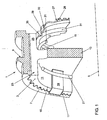
- a synchronizer 1 for a vehicle transmission is shown.
- a synchronizer body 3 of the synchronizer is fixedly connected to a main shaft, which in the Fig. 1 is indicated by dash-dotted lines with its axis 5.
- the synchronizer body 3 is provided on its outer circumference with a toothing 7 and carries over its toothing 7 an axially displaceable sliding sleeve. 9
- Fig. 1 is the synchronizer body 3 end formed with two opposite annular spaces 11, which are spaced from each other via a partition 13 in the axial direction.
- annular spaces 11 In the cylinder walls 15 of the annular spaces 11 continuous recesses 17 are formed in the axial direction, which interrupt the ring gear 7 of the synchronizer body 3.
- a synchronizing bolt 19 is arranged, which extends in the axial direction substantially over the entire length of the recess 17.
- the Indian Fig. 1 shown synchronizer bolt 19 is pressed over two, arranged in each case one of the annular spaces 11 Synchronfedem 21 against the shift sleeve 9.
- the Synchronfedem 21 are formed as Drahtringfedem.
- a groove 23 is shown with its one side wall 25.
- the side walls of the grooves 23 form rotational stops 25, one of which is shown in the sectional view.
- a synchronizing ring 27 is arranged with its synchronizing ring stop 29 or driver adjustable in a small angle of rotation.
- Fig. 1 is shown only on the right side of the synchronizer 3 of the synchronizer ring 27 and is omitted for reasons of clarity of the left side synchronizer ring 27.
- the shift sleeve 9 is axially displaced in the direction of a gear wheel, not shown, by means of a shift linkage, not shown, in a known manner in a single synchronization.
- the synchronizer latch 19 are taken from the shift sleeve 9.
- the synchronizer latch 19 press the synchronizer ring 27 with its synchronous taper 31 on a synchronizer cone of the gear, so that due to the resulting friction torque, the gear is taken in the direction of rotation and the synchronizer ring 27 abuts with its synchronizing ring stop 29 and driver against one of the rotational stops 25 and his ratchet teeth 28 blocks an axial movement of the shift sleeve 9.
- the synchronizer ring 27 used in the synchronizer 1 is shown.
- the synchronizer ring 27 is made of a sheet material of substantially the same material thickness in a drawing and punching process.
- the synchronizing ring stop 29 is formed as a flap extending in the axial direction, bent by the synchronizing ring 27.
- three equiangularly spaced lobes 29 are formed.
- the side edges 33 of the flap 29 form lateral abutment surfaces 34, which can be brought into contact respectively with associated rotational stops 25 of the synchronizer body 3.
- On its inner peripheral side of the synchronizer ring 27 is formed with its synchronous taper 31.
- the flap 29 has a centrally disposed between its side edges 33 centrally disposed bead 35, so that the flap 29 frontally enlarged by the bead 35, approximately V-shaped stop surface 36 for limiting the axial movement of the annular spring 21 is formed.
- the bead 35 of the flap 29 protrudes in accordance with the Fig. 1 radially into the annular spaces 11 of the synchronizer body 3 and with its tip of the wire ring spring 21 opposite.
- the Fig. 2 carries the synchronizer ring 27 at its periphery as external teeth, the sprocket teeth 28, which is interrupted by the three lobes 29.
- Each of the tabs 29 is spaced with its respective bead 35 over a free space a of the synchronous taper 31.
- a shape of the formed as a bead 35 forming portion can therefore be independent of the synchronous taper 31, as long as the tab 29 can be brought into contact with each of the synchronous body side torsion stops 25 and can act as an axial stop for the wire spring 21.
Landscapes
- Engineering & Computer Science (AREA)
- General Engineering & Computer Science (AREA)
- Mechanical Engineering (AREA)
- Mechanical Operated Clutches (AREA)
- Synchronisation In Digital Transmission Systems (AREA)
- Burglar Alarm Systems (AREA)
Description
- Die Erfindung betrifft eine Synchronisiereinrichtung gemäß dem Oberbegriff des Patentanspruches 1 und einen Synchronring gemäß dem Oberbegriff des Patentanspruches 10.
- Bekanntermaßen wird bei derzeit eingesetzten Synchronisiereinrichtungen für Fahrzeuggetriebe ein mit einer Hauptwelle verbundener Synchronkörper verwendet, der eine axial verschiebbare Schaltmuffe trägt und dem zumindest einseitig ein Synchronring zugeordnet ist, der gegenüber dem Synchronkörper axial verschiebbar ist. In umfangsseitigen Ausnehmungen des Synchronkörpers sind Druckstücke bzw. Synchronriegel gelagert, die über eine Synchronfeder gegen eine Schaltmuffe gedrückt werden, die vom Synchronkörper getragen ist.
- Die Synchronfeder kann auf unterschiedliche Weise realisiert sein: Vielfach ist die Synchronfeder eine Spiraldruckfeder, die einen Synchronriegel radial in die Schaltmuffe drückt. Alternativ kann die Synchronfeder als zumindest eine Ringfeder, etwa eine Drahtringfeder, ausgebildet sein, die innenumfangsseitig im Synchronkörper angeordnet ist und dabei die Synchronriegel in die Schaltmuffe drückt. Die Ringfeder ist dabei in Axialrichtung an einer Innenumfangswand des Synchronkörpers verschiebbar bzw. kann in der Axialrichtung.wandern.
- Aus der
FR-A-2 250 404 EP-A1-0 756 098 , derUS-A-4 776 228 und derEP-A1-0 816 704 bekannt. - Aus der
DE 35 19 811 A1 ist ein Synchronring für eine Synchronisiereinrichtung bekannt, der aus einem Blechmaterial im Stanz- und Ziehverfahren hergestellt ist. Die Mitnehmer bzw. Synchronanschläge des Synchronrings sind jeweils als ein sich in Axialrichtung erstreckender, vom Synchronring abgewinkelter Lappen ausgebildet, der sich zwischen den zugeordneten Verdrehanschlägen des Synchronrings bzw. der Schaltmuffe bewegen kann. - Aufgabe der Erfindung ist es, eine Synchronisiereinrichtung und einen Synchronring bereitzustellen, der eine kostengünstige und zuverlässige Halterung der Synchronringfeder in dem Synchronkörper ermöglicht.
- Die Aufgabe wird mit den Merkmalen des Patentanspruches 1 oder des Patentanspruches 10 gelöst. Vorteilhafte Weiterbildungen der Erfindung enthalten die weiteren Ansprüche. Erfindungsgemäß ist der als sich in Axialrichtung erstreckende, vom Synchronring abgewinkelte, vorzugsweise dünnwandige Lappen als ein Axialanschlag ausgebildet, der das axiale Wandern der Synchronfeder im Synchronkörper begrenzt. Dadurch kann bei geringem Materialeinsatz einerseits der Lappen des Synchronrings mit seinen Seitenkanten mit den Verdrehanschlägen in Anlage bringbar sein und andererseits der Lappen als Axialanschlag für die Synchronfeder, vorzugsweise Ringfeder, wirken. Die Erfindung kann dabei-sowohl für eine Einfach- als auch eine Mehrfachsynchronisierung verwendet werden. Das Fahrzeuggetriebe kann dabei als ein manuelles Getriebe, ein Doppelkupplungsgetriebe oder ein automatisiertes Schaltgetriebe ausgebildet sein.
- Gemäß der Erfindung ist der als Lappen ausgebildete Synchronringanschlag bzw. Mitnehmer mit einem Formabschnitt in Form einer sicke ausgebildet, der die Synchronfeder in Axialrichtung begrenzt. Dadurch ist es möglich, lediglich den Formabschnitt des Lappens als großflächigen Axialanschlag auszubilden, während der Lappen selbst eine geringe Materialstärke aufweisen kann. Dabei kann es bereits ausreichen, wenn lediglich der Formabschnitt des Lappens der Synchronfeder axial gegenüberliegt, während der Lappen selbst in Radialrichtung außerhalb der Synchronfeder vorgesehen ist. Weiterhin unterstützt der Formabschnitt auch die gegen die Verdrehanschläge anschlagenden Seitenkanten des Lappens in ihrer Formstabilität, so dass der dünnwandige Lappen sowohl in Axialrichtung als auch in Radialrichtung stabiler ausgebildet ist.
- Zur Ausbildung einer großflächigen Anschlagfläche für die Synchronfeder kann der Formabschnitt zumindest stirnseitig in dem Lappen ausgebildet sein, während dessen Seitenkanten - unabhängig vom Formabschnitt - in Anlage mit den Verdrehanschlägen des Synchronkörpers bzw. der Schaltmuffe bringbar sind.
- Bevorzugt kann der Lappen und/oder sein Formabschnitt über einen freien Zwischenraum von einem Synchronkegel des Synchronrings beabstandet sein. Der Synchronkegel ist dabei an einem Innenumfang des Synchronrings ausgebildet. Da in diesem Fall der Lappen bzw. sein Formabschnitt außer Anlage mit dem Synchronkegel sind, kann der Formabschnitt unabhängig vom Synchronkegel in verschiedenen Formvarianten ausgebildet werden.
- Erfindungsgemäß ist der Formabschnitt in einem fertigungstechnisch besonders einfach durchführbaren Prägeverfahren als eine in den Lappen geformte Sicke ausgebildet. Die Sicke kann sich bevorzugt im Wesentlichen parallel zwischen den Seitenkanten des Lappens mittig erstrecken. Dadurch ist einerseits die Formstabilität des Lappens erhöht und andererseits der Lappen mit seiner Sicke den Axialanschlag für die Synchronfeder bildet.
- Von Vorteil kann es sein, wenn der Synchronring zumindest mit seinem Lappen und dem Formabschnitt im Wesentlichen dieselbe Materialstärke aufweist. So wird erfindungsgemäß ein großflächiger Axialanschlag des Lappens lediglich durch seinen Formabschnitt ausgebildet. Eine zusätzliche, aufwändige Stauchung des Lappens zur Steigerung einer Anschlagfläche für die Anlage mit der Synchronfeder ist somit nicht notwendig.
- Der erfindungsgemäße Synchronring kann fertigungstechnisch besonders einfach sowie mit reduziertem Materialeinsatz aus einem Blechmaterial in einem Stanz- und/oder Ziehverfahren hergestellt werden.
- Nachfolgend ist ein Aüsführurigsbeispiel der Erfindung anhand der beigefügten Figuren beschrieben.
- Es zeigen:
- Fig. 1
- in einer perspektivischen Teilansicht einen Ausschnitt aus einer Synchronisiereinrichtung für ein Fahrzeuggetriebe; und
- Fig. 2
- in einer perspektivischen Ansicht den Synchronring für die Synchronisier- einrichtung.
- In der
Fig. 1 ist eine Synchronisiereinrichtung 1 für ein nicht dargestelltes Fahrzeuggetriebe gezeigt. Ein Synchronkörper 3 der Synchronisiereinrichtung ist fest mit einer Hauptwelle verbunden, die in derFig. 1 mit ihrer Achse 5 strichpunktiert angedeutet ist. Der Synchronkörper 3 ist an seinem Außenumfang mit einer Verzahnung 7 versehen und trägt über seiner Verzahnung 7 eine axial verschiebbare Schaltmuffe 9. - Gemäß der
Fig. 1 ist der Synchronkörper 3 stimseitig mit zwei gegenüberliegenden Ringräumen 11 ausgebildet, die über eine Trennwand 13 in Axialrichtung voneinander beabstandet sind. In den Zylinderwänden 15 der Ringräume 11 sind in Axialrichtung durchgehende Ausnehmungen 17 ausgebildet, die den Zahnkranz 7 des Synchronkörpers 3 unterbrechen. Eine dieser Ausnehmungen 17 ist in derFig. 1 gezeigt. In der gezeigten Ausnehmung 17 ist ein Synchronriegel 19 angeordnet, der sich in Axialrichtung im Wesentlichen über die gesamte Länge der Ausnehmung 17 erstreckt. Der in derFig. 1 gezeigte Synchronriegel 19 wird über zwei, in jeweils einem der Ringräume 11 angeordnete Synchronfedem 21 gegen die Schaltmuffe 9 gedrückt. Die Synchronfedem 21 sind als Drahtringfedem ausgebildet. - Weiter sind gemäß der
Fig. 1 sich in Axialrichtung erstreckende Nuten 23 im Außenumfang des Synchronkörpers 3 vorgesehen, von denen in derFig.1 eine Nut 23 mit ihrer einen Seitenwand 25 gezeigt ist. Die Seitenwände der Nuten 23 bilden Verdrehanschläge 25, von denen in der Schnittdarstellung einer gezeigt ist. Zwischen den Verdrehanschlägen 25 des Synchronkörpers 3 ist ein Synchronring 27 mit seinem Synchronringanschlag 29 bzw. Mitnehmer in einem kleinen Drehwinkel verstellbar angeordnet. In derFig. 1 ist lediglich auf der rechten Seite des Synchronkörpers 3 der Synchronring 27 dargestellt und ist aus Gründen der Übersichtlichkeit der linksseitig angeordnete Synchronring 27 weggelassen. - Bei einem Synchronisiervorgang wird in bekannter Weise bei einer Einfachsynchronisierung die Schaltmuffe 9 mittels eines nicht dargestellten Schaltgestänges in Richtung eines nicht gezeigten Gangrades axial verschoben. Dadurch werden die Synchronriegel 19 von der Schaltmuffe 9 mitgenommen. Die Synchronriegel 19 drücken dabei den Synchronring 27 mit seinem Synchroninnenkegel 31 auf einen Synchronkegel des Gangrads, so dass aufgrund des dabei entstehenden Reibmoments das Gangrad in Drehrichtung mitgenommen wird und der Synchronring 27 mit seinem Synchronringanschlag 29 bzw. Mitnehmer gegen einen der Verdrehanschläge 25 anschlägt und mit seinen Sperrzähnen 28 eine Axialbewegung der Schaltmuffe 9 sperrt.
- Alternativ wird bei einer Doppel- oder Mehrfachsynchronisierung der Synchronring 27 nicht unmittelbar auf das Gangrad gedrückt, sondern auf zusätzliche Synchronisierbauteile, die mit dem Gangrad verbunden sind.
- In der
Fig. 2 ist der in der Synchronisiereinrichtung 1 verwendete Synchronring 27 gezeigt. Der Synchronring 27 ist aus einem Blechmaterial von im wesentlichen derselben Materialstärke in einem Zieh- und Stanzverfahren hergestellt. Dabei ist der Synchronringanschlag 29 als ein sich in Axialrichtung erstreckender, vom Synchronring 27 abgebogener Lappen ausgebildet. Wie in derFig. 2 gezeigt ist, sind drei gleichwinklig voneinander beabstandete Lappen 29 geformt. Die Seitenkanten 33 des Lappens 29 bilden seitliche Anschlagflächen 34, die jeweils mit zugeordneten Verdrehanschlägen 25 des Synchronkörpers 3 in Anlage bringbar sind. An seiner Innenumfangsseite ist der Synchronring 27 mit seinem Synchroninnenkegel 31 ausgebildet. - Wie aus den
Fig. 1 und2 hervorgeht, weist der Lappen 29 eine zwischen seinen Seitenkanten 33 parallel verlaufende mittig angeordnete Sicke 35 auf, so dass der Lappen 29 stirnseitig eine durch die Sicke 35 vergrößerte, in etwa V-förmige Anschlagfläche 36 zur Begrenzung der Axialbewegung der Ringfeder 21 ausbildet. Die Sicke 35 des Lappens 29 ragt dabei gemäß derFig. 1 radial in die Ringräume 11 des Synchronkörpers 3 hinein und liegt mit ihrer Spitze der Drahtringfeder 21 gegenüber. Gemäß derFig. 2 trägt der Synchronring 27 an seinem Umfang als Außenverzahnung die Spenzähne 28, die durch die drei Lappen 29 unterbrochen ist. Jeder der Lappen 29 ist mit seiner jeweiligen Sicke 35 über einen freien Zwischenraum a von dem Synchroninnenkegel 31 beabstandet. Eine Formgebung des als Sicke 35 ausgebildeten Formabschnitts kann daher unabhängig von dem Synchroninnenkegel 31 erfolgen, solange der Lappen 29 jeweils mit den synchronkörperseitigen Verdrehanschlägen 25 in Anlage bringbar ist und als ein Axialanschlag für die Drahtringfeder 21 wirken kann. -
- 1
- Synchronisiereinrichtung
- 3
- Synchronkörper
- 5
- Achse der Hauptwelle
- 7.
- Verzahnung des Synchronkörpers
- 9
- Schaltmuffe
- 11
- Ringräume
- 13
- Trennwand
- 15
- Zylinderwand
- 17
- Ausnehmung
- 19
- Synchronriegel
- 21
- Drahtringfeder
- 23
- Nut
- 25
- Verdrehanschläge
- 27
- Synchronring
- 28
- Sperrzähne
- 29
- Synchronringanschlag
- 31
- Synchroninnenkegel
- 33
- Seitenkanten
- 34
- Anschlagfläche
- 35
- Sicke
- 36
- Anschlagfläche
- a
- freier Zwischenraum
Claims (10)
- Synchronisiereinrichtung für ein Fahrzeuggetriebe, mit zumindest einem Synchronring (27), der gegenüber einem Synchronkörper(3) axial verschiebbar ist, und mit zumindest einer synchronkörperseitig angeordneten Synchronfeder (21), wobei der Synchronring (27) mit einem Synchronringanschlag (29) zwischen zugeordneten Verdrehanschlägen (25) des Synchronkörpers (3) bzw, einer Schaltmuffe (9) verdrehbar ist, und der Synchronringanschlag (29) als ein sich in Axialrichtung erstreckender, vom Synchronring (27) abgewinkelter, vorzugsweise dünnwandiger Lappen ausgebildet ist, wobei der Lappen (29) als ein Axialanschlag ausgebildet ist, der ein axiales Wandern der Synchronfeder (21) im Synchronkörper (3) begrenzt, dadurch gekennzeichnet, dass der Synchronring (27) aus einem Blechmaterial hergestellt ist, in dem der Axialanschlag (35) als eine in dem Lappen (29) geformte Sicke ausgebildet ist.
- Synchronisiereinrichtung nach Anspruch 1, dadurch gekennzeichnet, dass die Sicke (35) sich im wesentlichen parallel zwischen den Seitenkanten (33) des Lappens (29) und/oder mittig erstreckt.
- Synchronisiereinrichtung nach einem der vorhergehenden Ansprüche, dadurch gekennzeichnet, dass der Lappen (29) und/oder seine sicke (35) der Synchronfeder (21) axial gegenüberliegt.
- Synchronisiereinrichtung nach einem der vorhergehenden Ansprüche, dadurch gekennzeichnet, dass der Lappen (29) eine stirnseitige Anschlagfläche (36) zur Begrenzung des axialen Wanderns der Synchronfeder (21) und/oder Seitenanschlagflächen (34) aufweist, die mit den Verdrehanschlägen (25) in Anlage bringbar sind.
- Synchronisiereinrichtung nach einem der vorhergehenden Ansprüche, dadurch gekennzeichnet, dass der Axialanschlag (35) zumindest stirnseitig in dem Lappen (29) ausgebildet ist.
- Synchronisiereinrichtung nach einem der vorhergehenden Ansprüche, dadurch gekennzeichnet, dass der Lappen (29) zumindest mit seinem Axialanschlag (35) in einen synchronkörperseitigen Ringraum (11) ragt, in dem die Synchronfeder (21) in Form einer Ringfeder angeordnet ist.
- Synchronisiereinrichtung nach einem der vorhergehenden Ansprüche, dadurch gekennzeichnet, dass der Axialanschlag (35) des Lappens (29) über einen freien Zwischenraum (a) von einem Synchronkegel (31) des Synchronrings (27) beabstandet ist.
- Synchronisiereinrichtung nach einem der vorhergehenden Ansprüche, dadurch gekennzeichnet, dass der Synchronring (27) zusammen mit seinem Lappen (29) und/oder dem Axialanschlag (35) im Wesentlichen dieselbe Materialstärke aufweisen.
- Synchronisiereinrichtung nach einem der vorhergehenden Ansprüche, dadurch gekennzeichnet, dass das Federelement (21) als eine sich ringförmig im Synchronkörper (3) erstreckende Feder, vorzugsweise eine Ringfeder ausgebildet ist.
- Synchronring (27) für eine Synchronisiereinrichtung (1) eines Fahrzeuggetriebes nach den Ansprüchen 1 bis 9,
mit einem Synchronringanschlag (29), der als ein vom Synchronring in Axialrichtung abgewinkelter, vorzugsweise dünnwandiger Lappen ausgebildet ist, wobei der Lappen mit einem Axialanschlag ausgebildet ist, der im eingebautem Zustand des Synchronrings ein axiales Wandern einer Federelements (21) im Synchronkörper (3) begrenzt, dadurch gekennzeichnet, dass der Synchronring (27) aus einem Blechmaterial hergestellt ist, in dem der Axialanschlag (35) als eine in dem Lappen (29) geformte Sicke ausgebildet ist.
Applications Claiming Priority (2)
| Application Number | Priority Date | Filing Date | Title |
|---|---|---|---|
| DE102005060572A DE102005060572A1 (de) | 2005-12-17 | 2005-12-17 | Synchronisiereinrichtung und Synchronring für eine Synchronisiereinrichtung |
| PCT/EP2006/011921 WO2007068432A1 (de) | 2005-12-17 | 2006-12-12 | Synchronisiereinrichtung und synchronring für eine synchronisiereinrichtung |
Publications (2)
| Publication Number | Publication Date |
|---|---|
| EP1966502A1 EP1966502A1 (de) | 2008-09-10 |
| EP1966502B1 true EP1966502B1 (de) | 2011-02-23 |
Family
ID=37907146
Family Applications (1)
| Application Number | Title | Priority Date | Filing Date |
|---|---|---|---|
| EP06829508A Active EP1966502B1 (de) | 2005-12-17 | 2006-12-12 | Synchronisiereinrichtung und synchronring für eine synchronisiereinrichtung |
Country Status (4)
| Country | Link |
|---|---|
| EP (1) | EP1966502B1 (de) |
| AT (1) | ATE499538T1 (de) |
| DE (2) | DE102005060572A1 (de) |
| WO (1) | WO2007068432A1 (de) |
Families Citing this family (6)
| Publication number | Priority date | Publication date | Assignee | Title |
|---|---|---|---|---|
| DE102008023031B4 (de) | 2008-05-09 | 2011-01-05 | Diehl Metall Stiftung & Co. Kg | Blech-Synchronring |
| KR101558402B1 (ko) * | 2008-06-18 | 2015-10-07 | 오엘리콘 프릭션 시스템즈 (져머니) 게엠베하 | 차량용 동기 링 및 기어 변경 방식의 변속기 |
| EP2196281B1 (de) * | 2008-12-11 | 2014-07-16 | Hoerbiger Antriebstechnik GmbH | Verfahren zur Herstellung eines Außensynchronrings |
| DE102009041518A1 (de) * | 2009-09-14 | 2011-03-24 | Hoerbiger Antriebstechnik Gmbh | Schaltmuffe für ein Schaltgetriebe |
| DE102016206569B4 (de) | 2016-04-19 | 2018-04-26 | Schaeffler Technologies AG & Co. KG | Synchro-Ringfeder mit Arretierfunktion |
| KR102172569B1 (ko) * | 2018-12-11 | 2020-11-02 | 이티알 주식회사 | 응력이 강화된 러그를 구비한 변속기용 동기 링 및 이의 제작방법 |
Family Cites Families (10)
| Publication number | Priority date | Publication date | Assignee | Title |
|---|---|---|---|---|
| FR2250404A5 (en) * | 1973-10-31 | 1975-05-30 | Citroen Sa | Synchroniser for a gearbox - tension springs normally prevent contact between pinion and synchronising ring |
| FR2390633A1 (fr) * | 1977-05-09 | 1978-12-08 | Renault | Dispositif de synchronisation perfectionne |
| DE3519811C2 (de) * | 1985-06-03 | 1994-05-11 | Borg Warner Automotive Gmbh | Träger für einen Synchronisierring |
| US4776228A (en) * | 1986-07-07 | 1988-10-11 | Chrysler Motors Corporation | Strutless synchronizer |
| FR2733560B1 (fr) * | 1995-04-28 | 1997-06-13 | Renault | Dispositif de synchronisation pour boite de vitesses mecanique |
| US5620075B1 (en) * | 1995-07-28 | 1999-08-17 | Borg Warner Automotive | C-shaped synchronizer spring |
| FR2750183B1 (fr) * | 1996-06-20 | 1998-07-31 | Peugeot | Synchroniseur double pour l'accouplement alternatif de deux pignons a un arbre de boite de vitesses |
| FR2751712B1 (fr) * | 1996-07-24 | 1998-10-30 | Valeo | Bague de synchronisation pour un synchroniseur de boite de vitesses |
| DE19718905B4 (de) * | 1997-05-05 | 2005-08-25 | Ina-Schaeffler Kg | Synchronring mit angeschweißten Mitnehmernasen |
| DE10203019A1 (de) * | 2002-01-26 | 2003-08-14 | Ina Schaeffler Kg | Mehrteiliger Synchronring einer Synchronisiereinrichtung |
-
2005
- 2005-12-17 DE DE102005060572A patent/DE102005060572A1/de not_active Withdrawn
-
2006
- 2006-12-12 EP EP06829508A patent/EP1966502B1/de active Active
- 2006-12-12 AT AT06829508T patent/ATE499538T1/de active
- 2006-12-12 WO PCT/EP2006/011921 patent/WO2007068432A1/de not_active Ceased
- 2006-12-12 DE DE502006008964T patent/DE502006008964D1/de active Active
Also Published As
| Publication number | Publication date |
|---|---|
| DE502006008964D1 (de) | 2011-04-07 |
| ATE499538T1 (de) | 2011-03-15 |
| EP1966502A1 (de) | 2008-09-10 |
| WO2007068432A1 (de) | 2007-06-21 |
| DE102005060572A1 (de) | 2007-06-21 |
Similar Documents
| Publication | Publication Date | Title |
|---|---|---|
| DE69609678T2 (de) | Synchronisiervorrichtung-Kupplung-Anordnung | |
| DE102008023031B4 (de) | Blech-Synchronring | |
| EP2478243B1 (de) | Übertragungsring für eine synchronisierungsbaugruppe für ein schaltgetriebe | |
| EP0985857A2 (de) | Rastierhülse für eine Schaltwelle | |
| WO1995003496A2 (de) | Getriebeschaltung mit sperrsynchronisierung | |
| DE102011103780A1 (de) | Synchronisationseinheit eines Schaltgetriebes | |
| DE102009027438A1 (de) | Synchronisierung für ein Schaltgetriebe | |
| EP2092206A1 (de) | Schiebemuffe einer synchronisiervorrichtung | |
| DE102011101557A1 (de) | Nachstelleinrichtung für eine Reibungskupplung | |
| EP1175569B1 (de) | Gebauter synchronkörper mit anschlagelement | |
| EP1966502B1 (de) | Synchronisiereinrichtung und synchronring für eine synchronisiereinrichtung | |
| DE102012001836B4 (de) | Schalttransmitter eines sperrsynchronisierten Schaltgetriebes | |
| DE102008049978A1 (de) | Schalteinheit mit Kupplungskörper | |
| EP3984764B1 (de) | Freilaufnabe mit feder aus kunststoff mit zelliger struktur | |
| DE102016122729A1 (de) | Synchroneinheit für ein Schaltgetriebe | |
| DE102014114276A1 (de) | Scheibenbremse | |
| DE102015121705A1 (de) | Kupplungsanordnung, insbesondere zum optionalen Verbinden eines Luftverdichters mit einer Antriebseinrichtung | |
| EP1239175B1 (de) | Schaltkupplung mit einer Synchronisiereinrichtung | |
| EP1208313B1 (de) | Synchronkörper aus einem formteil aus blech | |
| DE102007030507A1 (de) | Schiebemuffe | |
| EP2478244B1 (de) | Schaltmuffe für ein schaltgetriebe | |
| DE10018092B4 (de) | Synchronisiereinheit für Schaltkupplungen | |
| DE102015216364A1 (de) | Schaltkupplung | |
| DE60011320T2 (de) | Synchronisiereinrichtung für ein Fahrzeuggetriebe | |
| DE4319135C2 (de) | Zahnräderwechselgetriebe für Kraftfahrzeuge |
Legal Events
| Date | Code | Title | Description |
|---|---|---|---|
| PUAI | Public reference made under article 153(3) epc to a published international application that has entered the european phase |
Free format text: ORIGINAL CODE: 0009012 |
|
| 17P | Request for examination filed |
Effective date: 20080717 |
|
| AK | Designated contracting states |
Kind code of ref document: A1 Designated state(s): AT BE BG CH CY CZ DE DK EE ES FI FR GB GR HU IE IS IT LI LT LU LV MC NL PL PT RO SE SI SK TR |
|
| RIN1 | Information on inventor provided before grant (corrected) |
Inventor name: GARRETT, DAVID, L. Inventor name: ALBRECHT, MICHAEL Inventor name: STORMER, BORIS Inventor name: SPRECKELS, MARCUS |
|
| RAP1 | Party data changed (applicant data changed or rights of an application transferred) |
Owner name: VOLSKSWAGEN AKTIENGESELLSCHAFT Owner name: SULZER EUROFLAMM GERMANY GMBH |
|
| 17Q | First examination report despatched |
Effective date: 20090713 |
|
| GRAP | Despatch of communication of intention to grant a patent |
Free format text: ORIGINAL CODE: EPIDOSNIGR1 |
|
| GRAS | Grant fee paid |
Free format text: ORIGINAL CODE: EPIDOSNIGR3 |
|
| RAP1 | Party data changed (applicant data changed or rights of an application transferred) |
Owner name: SULZER FRICTION SYSTEMS (GERMANY) GMBH Owner name: VOLSKSWAGEN AKTIENGESELLSCHAFT |
|
| GRAA | (expected) grant |
Free format text: ORIGINAL CODE: 0009210 |
|
| AK | Designated contracting states |
Kind code of ref document: B1 Designated state(s): AT BE BG CH CY CZ DE DK EE ES FI FR GB GR HU IE IS IT LI LT LU LV MC NL PL PT RO SE SI SK TR |
|
| REG | Reference to a national code |
Ref country code: GB Ref legal event code: FG4D Free format text: NOT ENGLISH |
|
| REG | Reference to a national code |
Ref country code: CH Ref legal event code: EP |
|
| REG | Reference to a national code |
Ref country code: IE Ref legal event code: FG4D Free format text: LANGUAGE OF EP DOCUMENT: GERMAN |
|
| REF | Corresponds to: |
Ref document number: 502006008964 Country of ref document: DE Date of ref document: 20110407 Kind code of ref document: P |
|
| REG | Reference to a national code |
Ref country code: DE Ref legal event code: R096 Ref document number: 502006008964 Country of ref document: DE Effective date: 20110407 |
|
| REG | Reference to a national code |
Ref country code: NL Ref legal event code: VDEP Effective date: 20110223 |
|
| LTIE | Lt: invalidation of european patent or patent extension |
Effective date: 20110223 |
|
| PG25 | Lapsed in a contracting state [announced via postgrant information from national office to epo] |
Ref country code: ES Free format text: LAPSE BECAUSE OF FAILURE TO SUBMIT A TRANSLATION OF THE DESCRIPTION OR TO PAY THE FEE WITHIN THE PRESCRIBED TIME-LIMIT Effective date: 20110603 Ref country code: GR Free format text: LAPSE BECAUSE OF FAILURE TO SUBMIT A TRANSLATION OF THE DESCRIPTION OR TO PAY THE FEE WITHIN THE PRESCRIBED TIME-LIMIT Effective date: 20110524 Ref country code: SE Free format text: LAPSE BECAUSE OF FAILURE TO SUBMIT A TRANSLATION OF THE DESCRIPTION OR TO PAY THE FEE WITHIN THE PRESCRIBED TIME-LIMIT Effective date: 20110223 Ref country code: LT Free format text: LAPSE BECAUSE OF FAILURE TO SUBMIT A TRANSLATION OF THE DESCRIPTION OR TO PAY THE FEE WITHIN THE PRESCRIBED TIME-LIMIT Effective date: 20110223 Ref country code: PT Free format text: LAPSE BECAUSE OF FAILURE TO SUBMIT A TRANSLATION OF THE DESCRIPTION OR TO PAY THE FEE WITHIN THE PRESCRIBED TIME-LIMIT Effective date: 20110623 Ref country code: LV Free format text: LAPSE BECAUSE OF FAILURE TO SUBMIT A TRANSLATION OF THE DESCRIPTION OR TO PAY THE FEE WITHIN THE PRESCRIBED TIME-LIMIT Effective date: 20110223 |
|
| PG25 | Lapsed in a contracting state [announced via postgrant information from national office to epo] |
Ref country code: NL Free format text: LAPSE BECAUSE OF FAILURE TO SUBMIT A TRANSLATION OF THE DESCRIPTION OR TO PAY THE FEE WITHIN THE PRESCRIBED TIME-LIMIT Effective date: 20110223 Ref country code: CY Free format text: LAPSE BECAUSE OF FAILURE TO SUBMIT A TRANSLATION OF THE DESCRIPTION OR TO PAY THE FEE WITHIN THE PRESCRIBED TIME-LIMIT Effective date: 20110223 Ref country code: FI Free format text: LAPSE BECAUSE OF FAILURE TO SUBMIT A TRANSLATION OF THE DESCRIPTION OR TO PAY THE FEE WITHIN THE PRESCRIBED TIME-LIMIT Effective date: 20110223 Ref country code: SI Free format text: LAPSE BECAUSE OF FAILURE TO SUBMIT A TRANSLATION OF THE DESCRIPTION OR TO PAY THE FEE WITHIN THE PRESCRIBED TIME-LIMIT Effective date: 20110223 Ref country code: BG Free format text: LAPSE BECAUSE OF FAILURE TO SUBMIT A TRANSLATION OF THE DESCRIPTION OR TO PAY THE FEE WITHIN THE PRESCRIBED TIME-LIMIT Effective date: 20110523 |
|
| REG | Reference to a national code |
Ref country code: IE Ref legal event code: FD4D |
|
| PG25 | Lapsed in a contracting state [announced via postgrant information from national office to epo] |
Ref country code: DK Free format text: LAPSE BECAUSE OF FAILURE TO SUBMIT A TRANSLATION OF THE DESCRIPTION OR TO PAY THE FEE WITHIN THE PRESCRIBED TIME-LIMIT Effective date: 20110223 Ref country code: IE Free format text: LAPSE BECAUSE OF FAILURE TO SUBMIT A TRANSLATION OF THE DESCRIPTION OR TO PAY THE FEE WITHIN THE PRESCRIBED TIME-LIMIT Effective date: 20110223 Ref country code: EE Free format text: LAPSE BECAUSE OF FAILURE TO SUBMIT A TRANSLATION OF THE DESCRIPTION OR TO PAY THE FEE WITHIN THE PRESCRIBED TIME-LIMIT Effective date: 20110223 |
|
| PG25 | Lapsed in a contracting state [announced via postgrant information from national office to epo] |
Ref country code: RO Free format text: LAPSE BECAUSE OF FAILURE TO SUBMIT A TRANSLATION OF THE DESCRIPTION OR TO PAY THE FEE WITHIN THE PRESCRIBED TIME-LIMIT Effective date: 20110223 Ref country code: SK Free format text: LAPSE BECAUSE OF FAILURE TO SUBMIT A TRANSLATION OF THE DESCRIPTION OR TO PAY THE FEE WITHIN THE PRESCRIBED TIME-LIMIT Effective date: 20110223 Ref country code: CZ Free format text: LAPSE BECAUSE OF FAILURE TO SUBMIT A TRANSLATION OF THE DESCRIPTION OR TO PAY THE FEE WITHIN THE PRESCRIBED TIME-LIMIT Effective date: 20110223 |
|
| PLBE | No opposition filed within time limit |
Free format text: ORIGINAL CODE: 0009261 |
|
| STAA | Information on the status of an ep patent application or granted ep patent |
Free format text: STATUS: NO OPPOSITION FILED WITHIN TIME LIMIT |
|
| 26N | No opposition filed |
Effective date: 20111124 |
|
| PG25 | Lapsed in a contracting state [announced via postgrant information from national office to epo] |
Ref country code: PL Free format text: LAPSE BECAUSE OF FAILURE TO SUBMIT A TRANSLATION OF THE DESCRIPTION OR TO PAY THE FEE WITHIN THE PRESCRIBED TIME-LIMIT Effective date: 20110223 |
|
| REG | Reference to a national code |
Ref country code: DE Ref legal event code: R097 Ref document number: 502006008964 Country of ref document: DE Effective date: 20111124 |
|
| PG25 | Lapsed in a contracting state [announced via postgrant information from national office to epo] |
Ref country code: IT Free format text: LAPSE BECAUSE OF FAILURE TO SUBMIT A TRANSLATION OF THE DESCRIPTION OR TO PAY THE FEE WITHIN THE PRESCRIBED TIME-LIMIT Effective date: 20110223 |
|
| BERE | Be: lapsed |
Owner name: SULZER FRICTION SYSTEMS (GERMANY) G.M.B.H. Effective date: 20111231 Owner name: VOLSKSWAGEN A.G. Effective date: 20111231 |
|
| PG25 | Lapsed in a contracting state [announced via postgrant information from national office to epo] |
Ref country code: MC Free format text: LAPSE BECAUSE OF NON-PAYMENT OF DUE FEES Effective date: 20111231 |
|
| REG | Reference to a national code |
Ref country code: CH Ref legal event code: PL |
|
| GBPC | Gb: european patent ceased through non-payment of renewal fee |
Effective date: 20111212 |
|
| PG25 | Lapsed in a contracting state [announced via postgrant information from national office to epo] |
Ref country code: BE Free format text: LAPSE BECAUSE OF NON-PAYMENT OF DUE FEES Effective date: 20111231 Ref country code: CH Free format text: LAPSE BECAUSE OF NON-PAYMENT OF DUE FEES Effective date: 20111231 Ref country code: GB Free format text: LAPSE BECAUSE OF NON-PAYMENT OF DUE FEES Effective date: 20111212 Ref country code: LI Free format text: LAPSE BECAUSE OF NON-PAYMENT OF DUE FEES Effective date: 20111231 |
|
| REG | Reference to a national code |
Ref country code: AT Ref legal event code: MM01 Ref document number: 499538 Country of ref document: AT Kind code of ref document: T Effective date: 20111212 |
|
| PG25 | Lapsed in a contracting state [announced via postgrant information from national office to epo] |
Ref country code: LU Free format text: LAPSE BECAUSE OF NON-PAYMENT OF DUE FEES Effective date: 20111212 |
|
| PG25 | Lapsed in a contracting state [announced via postgrant information from national office to epo] |
Ref country code: AT Free format text: LAPSE BECAUSE OF NON-PAYMENT OF DUE FEES Effective date: 20111212 |
|
| PG25 | Lapsed in a contracting state [announced via postgrant information from national office to epo] |
Ref country code: IS Free format text: LAPSE BECAUSE OF FAILURE TO SUBMIT A TRANSLATION OF THE DESCRIPTION OR TO PAY THE FEE WITHIN THE PRESCRIBED TIME-LIMIT Effective date: 20110223 |
|
| PG25 | Lapsed in a contracting state [announced via postgrant information from national office to epo] |
Ref country code: TR Free format text: LAPSE BECAUSE OF FAILURE TO SUBMIT A TRANSLATION OF THE DESCRIPTION OR TO PAY THE FEE WITHIN THE PRESCRIBED TIME-LIMIT Effective date: 20110223 |
|
| PG25 | Lapsed in a contracting state [announced via postgrant information from national office to epo] |
Ref country code: HU Free format text: LAPSE BECAUSE OF FAILURE TO SUBMIT A TRANSLATION OF THE DESCRIPTION OR TO PAY THE FEE WITHIN THE PRESCRIBED TIME-LIMIT Effective date: 20110223 |
|
| REG | Reference to a national code |
Ref country code: FR Ref legal event code: PLFP Year of fee payment: 10 |
|
| REG | Reference to a national code |
Ref country code: FR Ref legal event code: PLFP Year of fee payment: 11 |
|
| REG | Reference to a national code |
Ref country code: FR Ref legal event code: PLFP Year of fee payment: 12 |
|
| P01 | Opt-out of the competence of the unified patent court (upc) registered |
Effective date: 20230526 |
|
| PGFP | Annual fee paid to national office [announced via postgrant information from national office to epo] |
Ref country code: FR Payment date: 20251223 Year of fee payment: 20 |
|
| PGFP | Annual fee paid to national office [announced via postgrant information from national office to epo] |
Ref country code: DE Payment date: 20251231 Year of fee payment: 20 |