EP1966562B1 - Holster für eine handwaffe, z.b. eine pistole oder einen revolver - Google Patents
Holster für eine handwaffe, z.b. eine pistole oder einen revolver Download PDFInfo
- Publication number
- EP1966562B1 EP1966562B1 EP06847075A EP06847075A EP1966562B1 EP 1966562 B1 EP1966562 B1 EP 1966562B1 EP 06847075 A EP06847075 A EP 06847075A EP 06847075 A EP06847075 A EP 06847075A EP 1966562 B1 EP1966562 B1 EP 1966562B1
- Authority
- EP
- European Patent Office
- Prior art keywords
- weapon
- button
- push
- locking member
- Prior art date
- Legal status (The legal status is an assumption and is not a legal conclusion. Google has not performed a legal analysis and makes no representation as to the accuracy of the status listed.)
- Active
Links
Images


Classifications
-
- F—MECHANICAL ENGINEERING; LIGHTING; HEATING; WEAPONS; BLASTING
- F41—WEAPONS
- F41C—SMALLARMS, e.g. PISTOLS, RIFLES; ACCESSORIES THEREFOR
- F41C33/00—Means for wearing or carrying smallarms
- F41C33/02—Holsters, i.e. cases for pistols having means for being carried or worn, e.g. at the belt or under the arm
- F41C33/0209—Pouch or pocket like containers for small arms covering all or most of the small arm
- F41C33/0227—Pouch or pocket like containers for small arms covering all or most of the small arm having a strap or other restraining element only covering the hammer or a part of the upper part of the small arm
-
- F—MECHANICAL ENGINEERING; LIGHTING; HEATING; WEAPONS; BLASTING
- F41—WEAPONS
- F41C—SMALLARMS, e.g. PISTOLS, RIFLES; ACCESSORIES THEREFOR
- F41C33/00—Means for wearing or carrying smallarms
- F41C33/02—Holsters, i.e. cases for pistols having means for being carried or worn, e.g. at the belt or under the arm
- F41C33/0263—Holsters, i.e. cases for pistols having means for being carried or worn, e.g. at the belt or under the arm having a locking system for preventing unauthorized or accidental removal of the small arm from the holster
Definitions
- the present invention relates to a belt or thigh or shoulder case for a handgun, such as a pistol or a revolver.
- the cases for a handgun and in particular the belt cases must satisfy several requirements that are most often contradictory.
- this type of case must allow ease of intervention, ie allow a quick exit of the weapon from the case and have all the security guarantees, ie do not authorize an unintentional release of the weapon whether by its own weight or by a third person seeking to steal the carrier's weapon.
- the cases are generally formed by a pocket housing the weapon and which comprises, at its upper part, an opening for introducing said weapon.
- This pocket is provided on at least one of these sides, fixing means on a receiving member carried by the user.
- fixing means are constituted, in the case of a belt case, by a passer supporting this pocket and, in the case of a shoulder case, by a harness connected to said pocket.
- the pocket is supported by a fastening system consisting of a plate and / or a strap.
- the butt of the weapon is disposed outside the pocket and the weapon is held by a safety tab, one end of which is secured to the pocket and the other end of which is fixed on said pocket by a fastening member, as for example a pressure member or a detent member.
- this safety tab hinders the return of the weapon in the holster after a voluntary release of this weapon.
- Holsters are also known which comprise a housing pocket of the weapon provided, at its upper part, with an opening for introducing the weapon and, at its rear part, with a support rocker of this movable weapon. successively vertically between a high position and a low position and by pivoting between a retracted position inside the pocket in which the weapon is locked in the up position against a fixed and fixed bracket of this pocket and a deployed position to the outside of said pocket and in which the weapon is released from the stirrup.
- This type of case is complex to implement and use and even if it prevents a third person takes the weapon out of the pocket, it does not have all the necessary security guarantees and especially it does not not allow a reintroduction of the weapon easily, because the rocker can return to the retracted position by a simple push before the reintroduction of the weapon.
- the invention aims to provide a holster for a handgun that is simple to implement and use and has all the necessary security guarantees.
- the invention therefore relates to a case for a handgun as described in claim 1.
- Fig. 1 schematically represented a case designated as a whole by the reference 10 for handgun 1, such as a pistol or a revolver.
- the case 10 can be used as a belt or thigh or shoulder case and consists of a pocket designated by the general reference 11 forming a housing for the weapon 1 and which comprises, at its upper part, an opening 12 for introducing this weapon 1.
- the weapon 1 comprises in particular a butt 1 a, a bridge 1b ( Figs. 1 and 2 ) and a barrel 1c provided on its underside with a series of notches 1d ( Figs. 4 and 5 ) for attaching an accessory, such as a sight assist system, a night vision system or a lighting system.
- an accessory such as a sight assist system, a night vision system or a lighting system.
- the pocket 11 is provided with fixing means on a receiving member carried by a user.
- the case is a belt case
- the fixing means consist of a loop 2 supporting the pocket 11.
- the pocket 11 is formed on two sides, respectively 11a and 11b, and has a front wall connecting the sides 11a and 11b. These sides 11a and 11b and the front wall 11c determine a receiving housing of the weapon 1.
- the pocket 11 comprises at its upper part, a tongue 15, a first end 15a is mounted on the side 11a of the pocket 11 and a second end 15b is provided with a detent member, such as a snap , not shown, on a tab 18 fixed on the opposite side 11b of said pocket 11.
- a detent member such as a snap
- the first end 15a of the tongue 15 is pivotally mounted on an axis 16 fixed on the side 11a of the pocket 11.
- the tongue is movable, after unlocking the end 15b of this tongue 15, between a first position above the pocket 11, as shown in solid lines at the Fig. 1 , to block the weapon and a second position tilted forward this pocket 11, as shown in phantom on this Fig. 1 .
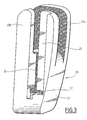
- the pocket 11 is provided with means for blocking the weapon 1 which comprise a support element designated by the general reference 20, shown in particular on the Figs. 1 to 3 .
- This support member 20 is formed by a body 21 on which are fixed the sides 11a and 11b of the bag 1.
- the body 21 is provided at its upper part with two legs, respectively 22a and 22b, vertical and parallel, providing between them a housing 23 intended to receive the bridge 1b of the weapon 1, as shown on the Figs. 1 and 2 .
- the means for blocking the weapon 1 in the pocket 11 also comprise a locking member 40 ( Fig. 4 to 6 ) and a pusher 30 for moving the locking member 40, as will be seen later.
- the pusher 30 comprises a first plate 31 extending parallel to the tabs 22a and 22b of the support member 20 and a second plate 32 extending perpendicularly to said tabs 22a and 22b and to the first plate 31.
- This second plate 32 is provided at its lower part with means 33 for moving the locking member 40 perpendicular to the lower face of the barrel 1c of the weapon 1 between an active position engaged in a notch 1d ( Fig. 4 ) to immobilize the weapon 1 and a retracted position ( Fig. 5 ) releasing the weapon 1.
- the first plate 31 of the pusher 30 is provided, at its upper part, with an extension 31a opening above the support member 20 and which is provided with a button 31b.
- the button 31b of the pusher 30 is accessible from the upper part of the pocket 11 to move the pusher 30 in a direction substantially parallel to the longitudinal axis of the barrel 1c of the weapon 1 placed in the pocket 11 so as to move the locking member 40 between the two positions.
- the support member 20 and provided with means for guiding the pusher 30.
- These guiding means shown in FIG. Fig. 3 are formed by a first groove 25 formed in the lug 22b and in the body 21 of the support member 20 for the first plate 31 of the pusher 30 and by a second groove 26 formed in the body 21, extending perpendicular to the first groove 26 for guiding the second plate 32 of the pusher 30.
- the pusher 30 is movable between a high rest position releasing the locking member 40 in its active position and a low position active maintaining said locking member in its retracted position.
- the pusher 30 is held in its upper position by an elastic member 35 ( Fig. 4 ) as for example a compression spring which is arranged between the lower edge of the first branch 31 of this pusher 30 and the bottom of the groove 26 of the body 21 of the support element 20 ( Fig. 3 ).
- an elastic member 35 Fig. 4
- a compression spring which is arranged between the lower edge of the first branch 31 of this pusher 30 and the bottom of the groove 26 of the body 21 of the support element 20 ( Fig. 3 ).
- the locking member 40 represented in particular on the Figs. 4 and 5 , is formed by a cleat 41 comprising, at a first end, at least one finger 42 intended to cooperate with a notch 1d of the barrel 1c of the weapon 1.
- the cleat 41 comprises two fingers 42 parallel to each other. This cleat 41 comprises at a second end, displacement means 43 complementary to the displacement means 33 carried by the pusher 30.
- the displacement means 33 carried by the second branch 32 of the pusher 30 are formed by at least one ramp 34 and, preferably, by two ramps 34 and the displacement means 43 carried by the catch 41 are formed by at least one ramp 44 and, preferably, by two ramps 44 of slope complementary to the ramps 34 of the pusher 30.
- the locking member 40 is returned to its active position represented in FIG. Fig. 4 by an elastic member 45, such as a compression spring.
- the means for guiding the locking member 40 during its displacement between the two positions are constituted by a groove 27 formed in the body 21 of the support member 20, this groove 27 extending perpendicular to the groove 26 guiding the second branch 32 of the pusher 30.
- the operator releases the tongue 15 by giving a push on the leg 18 so that this tongue 15 pivots towards the front of the pocket 11 around the axis 16 under the effect of the elastic member 17, as shown in phantom on the Fig. 1 .
- the operator can thus remove the weapon 1 from the pocket 11 of the case 10 ( Fig. 6 ).
- the cleat 41 retracts on the passage of the barrel 1 c of the weapon 1 to come again to lock in the notch 1d. Then, the operator puts back the tongue 15.
- the case according to the invention has the advantage, thanks to the various elements that compose it, to offer reliable retention of the weapon, while allowing easy extraction of the weapon by the operator.
Landscapes
- Engineering & Computer Science (AREA)
- General Engineering & Computer Science (AREA)
- Purses, Travelling Bags, Baskets, Or Suitcases (AREA)
- Toys (AREA)
Claims (7)
- Halfter für eine Faustfeuerwaffe (1), wie beispielsweise eine Pistole oder ein Revolver, die/der einen Kolben (1a), einen Abzugsbügel (1b) und einen Lauf (1c) umfasst, der an seiner Innenseite mit einer Reihe von transversalen Kerben (1d) zur Befestigung eines Zubehörs ausgestattet ist, wobei das Halfter (10) eine Tasche (11) zur Unterbringung der Waffe (1) umfasst, die aufweist:- in ihrem oberen Abschnitt eine Öffnung (12) zum Einführen der Waffe (1), an mindestens einer ihrer Seiten Mittel (2) zur Befestigung auf einem Aufnahmeorgan, das von einem Benutzer getragen wird, und- Blockiermittel (20, 30, 40) der Waffe (1) in der Tasche (11), die ein Stützelement (20) umfassen, das eine Aufnahme (23) für den Abzugsbügel (1b) der Waffe (1) aufweist, ausgestattet mit einem Verriegelungsorgan (40), das von einem Drücker (30) vom oberen Abschnitt der Tasche (11) verschiebbar ist, so wie das Verriegelungsorgan (40) vom Drücker (30) senkrecht zur Innenseite des Laufs (1c) zwischen einer aktiven, in einer Kerbe (1d) eingerasteten Stellung, um die Waffe (1) zu immobilisieren, und einer ausgerasteten Stellung, in der die Waffe freigegeben ist, verschiebbar ist, dadurch gekennzeichnet, dass der Drücker (30) gemäß einer Richtung etwa parallel zur Längsachse des Laufs (1c) der in der Tasche (11) platzierten Waffe (1) verschiebbar ist und einerseits eine erste Platte (31) aufweist, die sich parallel zu den Beinen (22a, 22b) des Stützelements (20) erstreckt, und eine zweite Platte (32), die sich senkrecht zu den Beinen (22a, 22b) erstreckt und in ihrem unteren Abschnitt mit Verschiebemitteln (33) des Verriegelungsorgans (40) ausgestattet ist und dass das Verriegelungsorgan (40) von einer Nase (41) gebildet wird, die an einem ersten Ende mindestens einen Finger (42) aufweist, der dazu bestimmt ist, in der aktiven Stellung der Nase (41) mit einer Kerbe (1d) des Laufs (1c) der Waffe (1) zusammenzuarbeiten, und an einem zweiten Ende zu den vom Drücker (30) getragenen Verschiebemitteln (33) komplementäre Verschiebemittel (43), wobei die Mittel (33, 43) von Rampen (34 ,44) mit komplementärer Neigung gebildet werden, die jeweils von der zweiten Platte (32) des Drückers (30) und vom zweiten Ende der Nase (41) getragen werden.
- Halfter nach Anspruch 1, dadurch gekennzeichnet, dass das Stützelement (20) von einem Befestigungskörper (21) der Tasche (11) gebildet wird und in seinem oberen Abschnitt von zwei vertikalen und parallelen Beinen (22a, 22b) gebildet wird, die zwischen sich die Aufnahme (23) ausbilden, wobei der Körper (21) und die Beine (22a, 22b) Führungsmittel (25, 26, 27) des Drückers (30) und des Verriegelungsorgans (40) aufweisen.
- Halfter nach Anspruch 1 oder 2, dadurch gekennzeichnet, dass die erste Platte (31) in ihrem oberen Abschnitt eine Verlängerung (31a) aufweist, die oberhalb des Stützelements (20) mündet und mit einem Knopf (31b) ausgestattet ist.
- Halfter nach einem der vorangehenden Ansprüche, dadurch gekennzeichnet, dass der Drücker (30) zwischen einer hohen Ruhestellung, in der das Verriegelungsorgan (40) in seine aktive Stellung freigegeben wird, und einer niedrigen aktiven Stellung, in der das Verriegelungsorgan (40) in seiner eingerasteten Stellung gehalten wird, verschiebbar ist.
- Halfter nach Anspruch 4, dadurch gekennzeichnet, dass der Drücker (30) von einem elastischen Organ (35), wie beispielsweise eine Druckfeder, in seiner hohen Stellung gehalten wird,
- Halfter nach einem der vorangehenden Ansprüche, dadurch gekennzeichnet, dass das Verriegelungsorgan (40) von einem elastischen Organ (45), wie beispielsweise eine Druckfeder, in seine aktive Stillung zurückgerufen wird.
- Halfter nach einem der Ansprüche 2 bis 6, dadurch gekennzeichnet, dass die Führungsmittel von zu den Platten (31, 32) des Drückers (30) und zur Nase (41) komplementären. Rillen (25, 26, 27) gebildet werden.
Applications Claiming Priority (2)
| Application Number | Priority Date | Filing Date | Title |
|---|---|---|---|
| FR0513383A FR2895495B1 (fr) | 2005-12-27 | 2005-12-27 | Etui pour une arme de poing, comme par exemple un pistolet ou un revolver |
| PCT/FR2006/002795 WO2007074227A2 (fr) | 2005-12-27 | 2006-12-19 | Etui pour une arme de poing, comme par exemple un pistolet ou un revolver |
Publications (2)
| Publication Number | Publication Date |
|---|---|
| EP1966562A2 EP1966562A2 (de) | 2008-09-10 |
| EP1966562B1 true EP1966562B1 (de) | 2012-08-01 |
Family
ID=36693983
Family Applications (1)
| Application Number | Title | Priority Date | Filing Date |
|---|---|---|---|
| EP06847075A Active EP1966562B1 (de) | 2005-12-27 | 2006-12-19 | Holster für eine handwaffe, z.b. eine pistole oder einen revolver |
Country Status (5)
| Country | Link |
|---|---|
| US (1) | US20090179054A1 (de) |
| EP (1) | EP1966562B1 (de) |
| ES (1) | ES2392186T3 (de) |
| FR (1) | FR2895495B1 (de) |
| WO (1) | WO2007074227A2 (de) |
Families Citing this family (7)
| Publication number | Priority date | Publication date | Assignee | Title |
|---|---|---|---|---|
| DE102007049954A1 (de) * | 2007-10-18 | 2009-04-23 | Heckler & Koch Gmbh | Waffenhalterung, Holster und Waffenhalterung |
| CZ303696B6 (cs) * | 2009-01-15 | 2013-03-20 | Benes@Miroslav | Pouzdro pro jednorucní strelnou zbran |
| BG1321U1 (bg) * | 2009-06-12 | 2010-05-31 | Димитър АНАСТАСОВ | Кобур за пистолет |
| US20110011904A1 (en) * | 2009-07-17 | 2011-01-20 | Howard Schultz | Locking holster with thumb drive |
| DE102010034445A1 (de) | 2010-08-16 | 2012-02-16 | Giesecke & Devrient Gmbh | Vorrichtung für die Überwachung der Vereinzelung von Blattgut |
| DE102019108863A1 (de) * | 2019-04-04 | 2020-10-08 | Krauss-Maffei Wegmann Gmbh & Co. Kg | Haltevorrichtung |
| FR3162837B1 (fr) | 2024-05-28 | 2026-05-01 | Gk Professional | Etui sécurisé pour arme de poing |
Family Cites Families (13)
| Publication number | Priority date | Publication date | Assignee | Title |
|---|---|---|---|---|
| US3866811A (en) * | 1973-04-16 | 1975-02-18 | Robert L Hamby | Holster safety clasp |
| US5284281A (en) * | 1991-10-04 | 1994-02-08 | Nichols Richard E D | Holster with trigger guard gripping device |
| US5518115A (en) * | 1994-09-22 | 1996-05-21 | Poly Vac Incorporated | Sterilization and storage container tray including grommets |
| US5449103A (en) * | 1994-10-31 | 1995-09-12 | Tilley; Michael A. | Security holster |
| US6267279B1 (en) * | 1995-07-26 | 2001-07-31 | Laser Products Ltd. | Hand weapon holstering systems |
| EP0970342A1 (de) * | 1997-03-13 | 2000-01-12 | Peter Spielberger | Holster für handfeuerwaffen |
| US6385890B1 (en) * | 2001-06-20 | 2002-05-14 | Sandro Amadini | Firearm locking mechanism |
| US6732891B2 (en) * | 2001-08-30 | 2004-05-11 | Locklear, Iii Burney | Secure, quick-release handgun holster |
| US6634527B2 (en) * | 2002-01-25 | 2003-10-21 | Chin-Sheng Liu | Carrying device of a pistol |
| US6752300B2 (en) * | 2002-06-06 | 2004-06-22 | Fobus International Ltd. | Holster for a handgun |
| US7461765B2 (en) * | 2003-08-07 | 2008-12-09 | Michaels Of Oregon Co. | Security hood for handgun holsters and the like |
| US20050205624A1 (en) * | 2004-03-11 | 2005-09-22 | Michaels Of Oregon Co. | Finger-actuated handgun retention device for holster |
| EP1766317B1 (de) * | 2004-05-11 | 2009-12-02 | PIKIELNY, Dov | Aufnahme für taktische ausrüstung mit zubehörbefestigungsschiene |
-
2005
- 2005-12-27 FR FR0513383A patent/FR2895495B1/fr not_active Expired - Fee Related
-
2006
- 2006-12-19 EP EP06847075A patent/EP1966562B1/de active Active
- 2006-12-19 ES ES06847075T patent/ES2392186T3/es active Active
- 2006-12-19 US US12/159,420 patent/US20090179054A1/en not_active Abandoned
- 2006-12-19 WO PCT/FR2006/002795 patent/WO2007074227A2/fr not_active Ceased
Also Published As
| Publication number | Publication date |
|---|---|
| WO2007074227A3 (fr) | 2007-08-16 |
| EP1966562A2 (de) | 2008-09-10 |
| ES2392186T3 (es) | 2012-12-05 |
| FR2895495A1 (fr) | 2007-06-29 |
| WO2007074227A2 (fr) | 2007-07-05 |
| US20090179054A1 (en) | 2009-07-16 |
| FR2895495B1 (fr) | 2008-07-18 |
Similar Documents
| Publication | Publication Date | Title |
|---|---|---|
| EP1949015B1 (de) | Holster für eine handwaffe, zum beispiel eine pistole oder einen revolver | |
| EP0634252B1 (de) | Taschenmesser mit einer verriegelbaren Klinge und einer Druckknopfentriegelungsvorrichtung | |
| EP1658468A1 (de) | Sicherheits- und haltevorrichtung für handwaffe | |
| FR3026311A1 (fr) | Talonniere de fixation d'une chaussure sur une planche de glisse | |
| EP1966562B1 (de) | Holster für eine handwaffe, z.b. eine pistole oder einen revolver | |
| EP0639752A1 (de) | System zum Tragen von Handfeuerwaffen | |
| EP3249343B1 (de) | Haltemodul für den lauf einer feuerwaffe, und modulare halterungsvorrichtung für feuerwaffe, die ein solches modul sowie ein haltemodul für den griff umfasst | |
| EP3531860A1 (de) | Sichere schnalle | |
| EP3450898B1 (de) | Karabiner mit linearer verriegelung | |
| EP2903702B1 (de) | Bindungssystem für ein touring-snowboard | |
| FR2530476A1 (fr) | Dispositif de fermeture pour ceintures de securite | |
| FR2985554A1 (fr) | Dispositif de connexion mecanique pour relier une charge a un support | |
| EP0983778B1 (de) | Lösbarer Anschlag für einen veschiebbaren Skibindungskörper | |
| FR2984480A1 (fr) | Porte-chargeur pour un chargeur d'une arme | |
| EP0312521A1 (de) | Pistolenscheide | |
| EP0661514B1 (de) | Waffe mit bewegbaren Verschlussstücken | |
| EP0778056A1 (de) | Schuhrückhaltevorrichtung auf einem Snowboard bzw. Ski oder ähnlichem | |
| EP0592032A1 (de) | Feuerwaffe mit beweglichem Magazin und Magazin für eine solche Waffe | |
| WO2003012361A1 (fr) | Etui pour arme de poing, comme par exemple un pistolet ou un revolver | |
| WO2005017440A1 (fr) | Etui pour arme de poing, comme par exemple un pistolet ou un revolver | |
| FR2951818A1 (fr) | Adaptateur de ceinture | |
| FR2836214A1 (fr) | Etui pour arme de poing, comme par exemple un pistolet ou un revolver | |
| FR2659430A1 (fr) | Etui pour arme de poing a ouverture frontale. | |
| FR2828274A1 (fr) | Etui pour arme de poing, comme par exemple un pistolet ou un revolver | |
| FR3162837A1 (fr) | Etui sécurisé pour arme de poing |
Legal Events
| Date | Code | Title | Description |
|---|---|---|---|
| PUAI | Public reference made under article 153(3) epc to a published international application that has entered the european phase |
Free format text: ORIGINAL CODE: 0009012 |
|
| 17P | Request for examination filed |
Effective date: 20080627 |
|
| AK | Designated contracting states |
Kind code of ref document: A2 Designated state(s): AT BE BG CH CY CZ DE DK EE ES FI FR GB GR HU IE IS IT LI LT LU LV MC NL PL PT RO SE SI SK TR |
|
| AX | Request for extension of the european patent |
Extension state: AL BA HR MK RS |
|
| 17Q | First examination report despatched |
Effective date: 20091207 |
|
| GRAP | Despatch of communication of intention to grant a patent |
Free format text: ORIGINAL CODE: EPIDOSNIGR1 |
|
| GRAS | Grant fee paid |
Free format text: ORIGINAL CODE: EPIDOSNIGR3 |
|
| GRAA | (expected) grant |
Free format text: ORIGINAL CODE: 0009210 |
|
| AK | Designated contracting states |
Kind code of ref document: B1 Designated state(s): AT BE BG CH CY CZ DE DK EE ES FI FR GB GR HU IE IS IT LI LT LU LV MC NL PL PT RO SE SI SK TR |
|
| AX | Request for extension of the european patent |
Extension state: AL BA HR MK RS |
|
| REG | Reference to a national code |
Ref country code: GB Ref legal event code: FG4D Free format text: NOT ENGLISH |
|
| REG | Reference to a national code |
Ref country code: CH Ref legal event code: EP Ref country code: AT Ref legal event code: REF Ref document number: 568903 Country of ref document: AT Kind code of ref document: T Effective date: 20120815 |
|
| REG | Reference to a national code |
Ref country code: IE Ref legal event code: FG4D Free format text: LANGUAGE OF EP DOCUMENT: FRENCH |
|
| REG | Reference to a national code |
Ref country code: DE Ref legal event code: R096 Ref document number: 602006031200 Country of ref document: DE Effective date: 20120927 |
|
| REG | Reference to a national code |
Ref country code: ES Ref legal event code: FG2A Ref document number: 2392186 Country of ref document: ES Kind code of ref document: T3 Effective date: 20121205 |
|
| REG | Reference to a national code |
Ref country code: NL Ref legal event code: VDEP Effective date: 20120801 |
|
| REG | Reference to a national code |
Ref country code: AT Ref legal event code: MK05 Ref document number: 568903 Country of ref document: AT Kind code of ref document: T Effective date: 20120801 |
|
| REG | Reference to a national code |
Ref country code: LT Ref legal event code: MG4D Effective date: 20120801 |
|
| PG25 | Lapsed in a contracting state [announced via postgrant information from national office to epo] |
Ref country code: FI Free format text: LAPSE BECAUSE OF FAILURE TO SUBMIT A TRANSLATION OF THE DESCRIPTION OR TO PAY THE FEE WITHIN THE PRESCRIBED TIME-LIMIT Effective date: 20120801 Ref country code: AT Free format text: LAPSE BECAUSE OF FAILURE TO SUBMIT A TRANSLATION OF THE DESCRIPTION OR TO PAY THE FEE WITHIN THE PRESCRIBED TIME-LIMIT Effective date: 20120801 Ref country code: CY Free format text: LAPSE BECAUSE OF FAILURE TO SUBMIT A TRANSLATION OF THE DESCRIPTION OR TO PAY THE FEE WITHIN THE PRESCRIBED TIME-LIMIT Effective date: 20120801 Ref country code: IS Free format text: LAPSE BECAUSE OF FAILURE TO SUBMIT A TRANSLATION OF THE DESCRIPTION OR TO PAY THE FEE WITHIN THE PRESCRIBED TIME-LIMIT Effective date: 20121201 Ref country code: LT Free format text: LAPSE BECAUSE OF FAILURE TO SUBMIT A TRANSLATION OF THE DESCRIPTION OR TO PAY THE FEE WITHIN THE PRESCRIBED TIME-LIMIT Effective date: 20120801 |
|
| PG25 | Lapsed in a contracting state [announced via postgrant information from national office to epo] |
Ref country code: PT Free format text: LAPSE BECAUSE OF FAILURE TO SUBMIT A TRANSLATION OF THE DESCRIPTION OR TO PAY THE FEE WITHIN THE PRESCRIBED TIME-LIMIT Effective date: 20121203 Ref country code: SI Free format text: LAPSE BECAUSE OF FAILURE TO SUBMIT A TRANSLATION OF THE DESCRIPTION OR TO PAY THE FEE WITHIN THE PRESCRIBED TIME-LIMIT Effective date: 20120801 Ref country code: SE Free format text: LAPSE BECAUSE OF FAILURE TO SUBMIT A TRANSLATION OF THE DESCRIPTION OR TO PAY THE FEE WITHIN THE PRESCRIBED TIME-LIMIT Effective date: 20120801 Ref country code: PL Free format text: LAPSE BECAUSE OF FAILURE TO SUBMIT A TRANSLATION OF THE DESCRIPTION OR TO PAY THE FEE WITHIN THE PRESCRIBED TIME-LIMIT Effective date: 20120801 Ref country code: GR Free format text: LAPSE BECAUSE OF FAILURE TO SUBMIT A TRANSLATION OF THE DESCRIPTION OR TO PAY THE FEE WITHIN THE PRESCRIBED TIME-LIMIT Effective date: 20121102 Ref country code: LV Free format text: LAPSE BECAUSE OF FAILURE TO SUBMIT A TRANSLATION OF THE DESCRIPTION OR TO PAY THE FEE WITHIN THE PRESCRIBED TIME-LIMIT Effective date: 20120801 |
|
| PGFP | Annual fee paid to national office [announced via postgrant information from national office to epo] |
Ref country code: IT Payment date: 20121213 Year of fee payment: 7 |
|
| PG25 | Lapsed in a contracting state [announced via postgrant information from national office to epo] |
Ref country code: NL Free format text: LAPSE BECAUSE OF FAILURE TO SUBMIT A TRANSLATION OF THE DESCRIPTION OR TO PAY THE FEE WITHIN THE PRESCRIBED TIME-LIMIT Effective date: 20120801 |
|
| PG25 | Lapsed in a contracting state [announced via postgrant information from national office to epo] |
Ref country code: RO Free format text: LAPSE BECAUSE OF FAILURE TO SUBMIT A TRANSLATION OF THE DESCRIPTION OR TO PAY THE FEE WITHIN THE PRESCRIBED TIME-LIMIT Effective date: 20120801 Ref country code: DK Free format text: LAPSE BECAUSE OF FAILURE TO SUBMIT A TRANSLATION OF THE DESCRIPTION OR TO PAY THE FEE WITHIN THE PRESCRIBED TIME-LIMIT Effective date: 20120801 Ref country code: EE Free format text: LAPSE BECAUSE OF FAILURE TO SUBMIT A TRANSLATION OF THE DESCRIPTION OR TO PAY THE FEE WITHIN THE PRESCRIBED TIME-LIMIT Effective date: 20120801 Ref country code: CZ Free format text: LAPSE BECAUSE OF FAILURE TO SUBMIT A TRANSLATION OF THE DESCRIPTION OR TO PAY THE FEE WITHIN THE PRESCRIBED TIME-LIMIT Effective date: 20120801 |
|
| PG25 | Lapsed in a contracting state [announced via postgrant information from national office to epo] |
Ref country code: SK Free format text: LAPSE BECAUSE OF FAILURE TO SUBMIT A TRANSLATION OF THE DESCRIPTION OR TO PAY THE FEE WITHIN THE PRESCRIBED TIME-LIMIT Effective date: 20120801 |
|
| PLBE | No opposition filed within time limit |
Free format text: ORIGINAL CODE: 0009261 |
|
| STAA | Information on the status of an ep patent application or granted ep patent |
Free format text: STATUS: NO OPPOSITION FILED WITHIN TIME LIMIT |
|
| BERE | Be: lapsed |
Owner name: GK PROFESSIONAL Effective date: 20121231 |
|
| 26N | No opposition filed |
Effective date: 20130503 |
|
| PG25 | Lapsed in a contracting state [announced via postgrant information from national office to epo] |
Ref country code: BG Free format text: LAPSE BECAUSE OF FAILURE TO SUBMIT A TRANSLATION OF THE DESCRIPTION OR TO PAY THE FEE WITHIN THE PRESCRIBED TIME-LIMIT Effective date: 20121101 Ref country code: MC Free format text: LAPSE BECAUSE OF NON-PAYMENT OF DUE FEES Effective date: 20121231 |
|
| REG | Reference to a national code |
Ref country code: CH Ref legal event code: PL |
|
| GBPC | Gb: european patent ceased through non-payment of renewal fee |
Effective date: 20121219 |
|
| REG | Reference to a national code |
Ref country code: DE Ref legal event code: R097 Ref document number: 602006031200 Country of ref document: DE Effective date: 20130503 |
|
| REG | Reference to a national code |
Ref country code: IE Ref legal event code: MM4A |
|
| PG25 | Lapsed in a contracting state [announced via postgrant information from national office to epo] |
Ref country code: BE Free format text: LAPSE BECAUSE OF NON-PAYMENT OF DUE FEES Effective date: 20121231 |
|
| PG25 | Lapsed in a contracting state [announced via postgrant information from national office to epo] |
Ref country code: LI Free format text: LAPSE BECAUSE OF NON-PAYMENT OF DUE FEES Effective date: 20121231 Ref country code: CH Free format text: LAPSE BECAUSE OF NON-PAYMENT OF DUE FEES Effective date: 20121231 Ref country code: IE Free format text: LAPSE BECAUSE OF NON-PAYMENT OF DUE FEES Effective date: 20121219 |
|
| PG25 | Lapsed in a contracting state [announced via postgrant information from national office to epo] |
Ref country code: GB Free format text: LAPSE BECAUSE OF NON-PAYMENT OF DUE FEES Effective date: 20121219 |
|
| PG25 | Lapsed in a contracting state [announced via postgrant information from national office to epo] |
Ref country code: TR Free format text: LAPSE BECAUSE OF FAILURE TO SUBMIT A TRANSLATION OF THE DESCRIPTION OR TO PAY THE FEE WITHIN THE PRESCRIBED TIME-LIMIT Effective date: 20120801 |
|
| PG25 | Lapsed in a contracting state [announced via postgrant information from national office to epo] |
Ref country code: LU Free format text: LAPSE BECAUSE OF NON-PAYMENT OF DUE FEES Effective date: 20121219 |
|
| PG25 | Lapsed in a contracting state [announced via postgrant information from national office to epo] |
Ref country code: HU Free format text: LAPSE BECAUSE OF FAILURE TO SUBMIT A TRANSLATION OF THE DESCRIPTION OR TO PAY THE FEE WITHIN THE PRESCRIBED TIME-LIMIT Effective date: 20061219 |
|
| PG25 | Lapsed in a contracting state [announced via postgrant information from national office to epo] |
Ref country code: IT Free format text: LAPSE BECAUSE OF NON-PAYMENT OF DUE FEES Effective date: 20131231 |
|
| REG | Reference to a national code |
Ref country code: FR Ref legal event code: PLFP Year of fee payment: 10 |
|
| PG25 | Lapsed in a contracting state [announced via postgrant information from national office to epo] |
Ref country code: IT Free format text: LAPSE BECAUSE OF NON-PAYMENT OF DUE FEES Effective date: 20131219 |
|
| REG | Reference to a national code |
Ref country code: FR Ref legal event code: PLFP Year of fee payment: 11 |
|
| REG | Reference to a national code |
Ref country code: FR Ref legal event code: PLFP Year of fee payment: 12 |
|
| PGFP | Annual fee paid to national office [announced via postgrant information from national office to epo] |
Ref country code: DE Payment date: 20181211 Year of fee payment: 13 |
|
| PGFP | Annual fee paid to national office [announced via postgrant information from national office to epo] |
Ref country code: ES Payment date: 20190125 Year of fee payment: 13 |
|
| REG | Reference to a national code |
Ref country code: DE Ref legal event code: R119 Ref document number: 602006031200 Country of ref document: DE |
|
| PG25 | Lapsed in a contracting state [announced via postgrant information from national office to epo] |
Ref country code: DE Free format text: LAPSE BECAUSE OF NON-PAYMENT OF DUE FEES Effective date: 20200701 |
|
| REG | Reference to a national code |
Ref country code: ES Ref legal event code: FD2A Effective date: 20210526 |
|
| PG25 | Lapsed in a contracting state [announced via postgrant information from national office to epo] |
Ref country code: ES Free format text: LAPSE BECAUSE OF NON-PAYMENT OF DUE FEES Effective date: 20191220 |
|
| PGFP | Annual fee paid to national office [announced via postgrant information from national office to epo] |
Ref country code: FR Payment date: 20251114 Year of fee payment: 20 |