EP1966593B1 - Aus einem gitter und einem polarisator zusammengesetzter biosensor mit eindimensionalen sub-diffraktions-begrenzten öffnungen - Google Patents
Aus einem gitter und einem polarisator zusammengesetzter biosensor mit eindimensionalen sub-diffraktions-begrenzten öffnungen Download PDFInfo
- Publication number
- EP1966593B1 EP1966593B1 EP06832204A EP06832204A EP1966593B1 EP 1966593 B1 EP1966593 B1 EP 1966593B1 EP 06832204 A EP06832204 A EP 06832204A EP 06832204 A EP06832204 A EP 06832204A EP 1966593 B1 EP1966593 B1 EP 1966593B1
- Authority
- EP
- European Patent Office
- Prior art keywords
- polarizer
- grid
- sensor
- sensor according
- suppressed
- Prior art date
- Legal status (The legal status is an assumption and is not a legal conclusion. Google has not performed a legal analysis and makes no representation as to the accuracy of the status listed.)
- Ceased
Links
- 230000005284 excitation Effects 0.000 claims abstract description 28
- 238000004020 luminiscence type Methods 0.000 claims abstract description 19
- 230000005855 radiation Effects 0.000 claims abstract description 19
- 238000000034 method Methods 0.000 claims abstract description 11
- 230000005540 biological transmission Effects 0.000 claims abstract description 7
- 238000001514 detection method Methods 0.000 claims abstract description 5
- 238000003491 array Methods 0.000 claims abstract description 3
- 239000011521 glass Substances 0.000 claims description 6
- 238000010521 absorption reaction Methods 0.000 claims description 4
- 230000003098 cholesteric effect Effects 0.000 claims description 4
- 238000005530 etching Methods 0.000 claims description 3
- 238000001914 filtration Methods 0.000 claims description 3
- 230000001678 irradiating effect Effects 0.000 claims 1
- 230000010287 polarization Effects 0.000 description 3
- 230000001419 dependent effect Effects 0.000 description 2
- 239000010408 film Substances 0.000 description 2
- 239000000463 material Substances 0.000 description 2
- 230000001629 suppression Effects 0.000 description 2
- 239000004372 Polyvinyl alcohol Substances 0.000 description 1
- 239000004990 Smectic liquid crystal Substances 0.000 description 1
- 239000006096 absorbing agent Substances 0.000 description 1
- 230000000694 effects Effects 0.000 description 1
- 230000005684 electric field Effects 0.000 description 1
- 239000012530 fluid Substances 0.000 description 1
- PNDPGZBMCMUPRI-UHFFFAOYSA-N iodine Chemical class II PNDPGZBMCMUPRI-UHFFFAOYSA-N 0.000 description 1
- 235000019422 polyvinyl alcohol Nutrition 0.000 description 1
- 229920002451 polyvinyl alcohol Polymers 0.000 description 1
- 239000002096 quantum dot Substances 0.000 description 1
- 238000000926 separation method Methods 0.000 description 1
- 238000006467 substitution reaction Methods 0.000 description 1
- 239000000758 substrate Substances 0.000 description 1
- 239000010409 thin film Substances 0.000 description 1
Images


Classifications
-
- G—PHYSICS
- G01—MEASURING; TESTING
- G01N—INVESTIGATING OR ANALYSING MATERIALS BY DETERMINING THEIR CHEMICAL OR PHYSICAL PROPERTIES
- G01N21/00—Investigating or analysing materials by the use of optical means, i.e. using sub-millimetre waves, infrared, visible or ultraviolet light
- G01N21/62—Systems in which the material investigated is excited whereby it emits light or causes a change in wavelength of the incident light
- G01N21/63—Systems in which the material investigated is excited whereby it emits light or causes a change in wavelength of the incident light optically excited
- G01N21/64—Fluorescence; Phosphorescence
- G01N21/645—Specially adapted constructive features of fluorimeters
- G01N21/648—Specially adapted constructive features of fluorimeters using evanescent coupling or surface plasmon coupling for the excitation of fluorescence
-
- Y—GENERAL TAGGING OF NEW TECHNOLOGICAL DEVELOPMENTS; GENERAL TAGGING OF CROSS-SECTIONAL TECHNOLOGIES SPANNING OVER SEVERAL SECTIONS OF THE IPC; TECHNICAL SUBJECTS COVERED BY FORMER USPC CROSS-REFERENCE ART COLLECTIONS [XRACs] AND DIGESTS
- Y10—TECHNICAL SUBJECTS COVERED BY FORMER USPC
- Y10T—TECHNICAL SUBJECTS COVERED BY FORMER US CLASSIFICATION
- Y10T436/00—Chemistry: analytical and immunological testing
- Y10T436/11—Automated chemical analysis
Definitions
- This application is related to the field of biosensors and more specifically to sub-wavelength biosensors employing an aperture grid and a polarizer.
- Biosensor technology is well-known in the art.
- WO 2006/136991 entitled "Luminescence sensors using sub-wavelength apertures or slits” 'discloses a biosensor with sub-wavelength spatial resolution operating inside a fluid.
- light is reflected on apertures with at least one transversal dimension below the diffraction limit. This results in an evanescent field within the apertures, which is used for exciting the contained luminophores.
- the luminescence that is generated exits the apertures on both a reflecting and non-reflecting side, which results in a separation of the excitation radiation from the luminescence radiation at the non-reflecting side. Background luminescence generated on the excitation side of the apertures is also suppressed by the reflection effect.
- slits are apertures with a first lateral (i.e., in the plane of the slits) dimension below the diffraction limit and a second lateral dimension , above the diffraction limit.
- the advantage of slits is that the suppression of light becomes polarization-dependent.
- the excitation-light can be suppressed by using the correct polarization (electric field is substantially parallel to the first lateral dimension of the slits), while a large portion of the luminescence is not suppressed, as it is generally not polarized. The resultant extra luminescence is able to reach a detector.
- WO2007/034395 entitled “Luminescence Sensor Comprising at Least Two Wire Grids,” combines two aperture grids positioned substantially perpendicular to one another. The combination of the aperture grids creates apertures with the advantages of the aperture biosensor while lacking the disadvantage of the apertures.
- the biosensor comprises a grid (120) 5 defined as arrays of apertures with the apertures having a first dimension below and a second dimension above the diffraction limit of the excitation light (102) in a medium, a polarizer (115), and luminophores (117) positioned in a volume selected from the group consisting of: the volume inside the apertures of the grid (120), the volume in between the array of slits (120) and the polarizer (115) and a volume that extends into the polarizer (115), wherein the grid (120) provides a transmission axis extending in a first direction and the polarizer (115) provides a transmission axis extending in a second direction, the first direction and the second direction being substantially perpendicular,
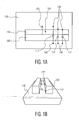
- FIG. 1A illustrates a first exemplary embodiment of a biosensor 110 in accordance with the principles of the invention.
- excitation light 102 illuminates biosensor 110, which is composed of a polarizer 115 and an aperture grid 120.
- the polarizer 115 and aperture grid 120 are positioned or oriented such that their respective transmission axes are substantially perpendicular to each other.
- excitation radiation or light 102 is polarized such that it is not suppressed by the polarizer 115 but is suppressed by aperture grid 120.
- the resultant reflected beam 125 is directed away from aperture grid 120.
- Luminophores 117 are contained between polarizer 115 and aperture grid 120.
- the luminophores 117 are preferably adhered to the aperture grid 120.
- luminophores 117 are adhered to the surface of polarizer 115 facing aperture grid 120.
- the molecules that are of interest are conventionally labeled with a luminophore and adheres to specific capture molecules that are present on the surface.
- adhered targets are detected with a secondary capture molecule that is labeled with a luminophore and adheres to immobilized targets or adheres to the fraction unbound capture molecule.
- the luminophores themselves are indirectly attached via the adhered targets or detection molecules.
- Luminophores may be organic fluorophores, quantum dots, chemiluminescent molecules, or electroluminescent molecules.
- polarizer 115 When energy from light 102 strikes luminophores 117, luminescence is generated in an omni pattern and only a portion of the light is directed to aperture grid 120 and a portion is directed toward polarizer 115. This is illustrated by the two beams 130 and 140, respectively, in the plane of Figure 1A . In this case beam 140 will encounter aperture grid 120 and be passed to a detector (not shown).
- polarizer 115 when polarizer 115 is a dichroic polarizer, beam 130 may be partly absorbed and partly transmitted by polarizer 115.
- polarizer 115 when polarizer 115 is a birefringent stack polarizer, beam 130 may be partly reflected and partly transmitted. In the case, the partly reflected beam 130 enhance the signal strength of beam 140.
- the aperture grid 120 and polarizer 115 may be selected as dichroic polarizers based on an oriented polarization dependent absorber.
- a polyvinylalcohol material may be modified with a diachronic dye or iodine crystals to achieve the desired characteristics.
- a smectic polarizer can be used to produce a very thin film, in the order of 2 to 6 micrometers on a substrate. As it is densely crosslinked it is accessible for further processing steps such as lithographic steps to produce a grid polarizer.
- polarizer 115 may be a reflecting polarizer, e.g., DBEF polarizer. Such polarizers are well-known in the art and need do be discussed herein. See for example, US Patent Nos. 5,094,788 ; 5,122,905 ; and 5,122,906 .
- Figure 1B illustrates a prospective view of biosensor 110 shown in Figure 1A .
- aperture grid 120 is composed of apertures (slots, slits) with a second dimension (above the diffraction limit) significantly larger (here drawn as extending from infinity to +infinity) than the first dimension (below the diffraction limit).
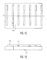
- Figure 1C illustrates a top view of a biosensor in accordance with the principles of the present invention.
- an aperture grid 120 is composed of a plurality of apertures having rectangular shape.
- Each aperture has a first dimension significantly smaller than a second direction.
- the first dimension is selected to be below the diffraction limit of the excitation light (102), while the second dimension is selected to be above the diffraction limit of the excitation light (102).
- Figure 1D illustrates a cross-section view, through section A-A, of the aperture grid shown in Figure 1C .
- This view illustrates how apertures are etched into the material to form aperture grid 120.
- luminophores 117 located in the volume of the apertures.
- Figure 2 illustrates a second exemplary embodiment of the invention.
- the location of aperture grid 120 and polarizer 115 are switched and excitation light 102 is suppressed by polarizer 115.
- Luminophores 117 are included between aperture grid 120 and polarizer 115, as previously discussed, and in this example, adhered on, or very close to the surface of polarizer 115.
- the excitation volume (i.e., the volume where the intensity of the excitation light is sufficiently high for the generation of appreciable luminescence) is determined by the rate of absorption in polarizer 115.
- the advantage of this is-that-the emitted luminescence is increased due to light reflecting from the aperture grid 120 towards the detector.
- a dichroic dye that may be used for polarizer 115 may have a narrow absorption band. This absorption band may be chosen such that it absorbs energy at the wavelength of the excitation light 102 but transmits at the wavelength of the emitted beam 140. In this case the intensity of beam 140 may be further enhanced.
- the polarizer layer 115 may consist of a quarterwave film, optimized for the wavelength of the excitation light 102 and a film consisting of a cholesteric network.
- the cholesteric network selectively reflects the non-used part of the beam 102 and transmits all emitted light 140 in addition to part of the reflected light 130.
- the advantage of the cholesteric network is that it has a very steep reflection band thus enabling discrimination between the excitation and the luminescence wavelengths.
- Figure 3 illustrates a third exemplary embodiment of the present invention wherein a glass plate 310 is introduced between polarizer 115 and aperture grid 120.
- Figure 4 illustrates a fourth exemplary embodiment of the present invention wherein a glass plate 410 is introduced in contact with aperture grid 120.
- the aperture grid 120 is sandwiched between (at least) polarizer 115 and glass-plate 410 and forms flow channels by which luminophores 117 may be introduced in the volume between the slots of aperture grid 120.
- Figure 5 illustrates another exemplary embodiment of the present invention wherein polarizer 115 is etched in the region corresponding to the slots 520 of aperture grid 120.
- This embodiment of the invention is advantageous as the extra volume 510 created by the etching has full excitation power and can be tuned by varying the depth of the etching.
- additional filtering devices such as a polarizer and/or additional bandpass filters, may be incorporated selectively included.
- the additional polarizer and/or bandpass filters may be used to suppress background light or filter both the excitation and emission wavelengths.
Landscapes
- Health & Medical Sciences (AREA)
- Nuclear Medicine, Radiotherapy & Molecular Imaging (AREA)
- Physics & Mathematics (AREA)
- Life Sciences & Earth Sciences (AREA)
- Chemical & Material Sciences (AREA)
- Analytical Chemistry (AREA)
- Biochemistry (AREA)
- General Health & Medical Sciences (AREA)
- General Physics & Mathematics (AREA)
- Immunology (AREA)
- Pathology (AREA)
- Investigating, Analyzing Materials By Fluorescence Or Luminescence (AREA)
- Investigating Or Analysing Materials By Optical Means (AREA)
Claims (18)
- Lumineszenzsensor mit einem Polarisator (115), dadurch gekennzeichnet, dass dieser weiterhin umfasst:ein Gitter (120), welches als Arrays von Öffnungen definiert ist, wobei die Öffnungen eine erste Dimension unterhalb einer Diffraktionsgrenze eines Anregungslichts (102) und eine zweite Dimension oberhalb der Diffraktionsgrenze des Anregungslichts (102) in einem Medium aufweisen; sowieLuminophoren (117), die in einem Volumen positioniert sind, welches aus der Gruppe, bestehend aus dem Volumen innerhalb einer Öffnung des Gitters (120), dem Volumen zwischen dem Array von Öffnungen und dem Polarisator (115) und einem Volumen, das sich in den Polarisator (115) erstreckt, ausgewählt wird, wobei das Gitter (120) eine Transmissionsachse vorsieht, die sich in einer ersten Richtung erstreckt, und der Polarisator (115) eine Transmissionsachse vorsieht, die sich in einer zweiten Richtung erstreckt, wobei die erste Richtung und die zweite Richtung im Wesentlichen senkrecht zueinander verlaufen.
- Sensor nach Anspruch 1, welcher weiterhin umfasst:eine Glasplatte (310) zwischen dem Polarisator (115) und dem Gitter (120).
- Sensor nach Anspruch 1, welcher weiterhin umfasst:eine Glasplatte (410) in Kontakt mit dem Gitter (120).
- Sensor nach Anspruch 1, welcher weiterhin umfasst:mehrere in den Polarisator (115) geätzte Flächen, wobei die Flächen den Öffnungen in dem Gitter (120) entsprechen.
- Sensor nach Anspruch 4, wobei die Ätztiefe variabel ist.
- Sensor nach Anspruch 1, wobei der Sensor mit Anregungsstrahlung (102) bestrahlt wird, wobei die Anregungsstrahlung (102) so polarisiert wird, dass sie durch zumindest das Gitter (120) oder den Polarisator (115) im Wesentlichen unterdrückt und durch zumindest das andere/den anderen der beiden, Gitter (120) oder Polarisator (115), im Wesentlichen nicht unterdrückt wird.
- Sensor nach Anspruch 6, wobei die Anregungsstrahlung (102) so polarisiert wird, dass diese durch den Polarisator (115), der von der Anregungsstrahlungsquelle am weitesten entfernt positioniert ist, im Wesentlichen unterdrückt und durch das Gitter (120), das in nächster Nähe der Anregungsstrahlungsquelle positioniert ist, im Wesentlichen nicht unterdrückt wird.
- Sensor nach Anspruch 1, wobei der Polarisator (115) eine Oberseite aufweist, wobei das Gitter (120) auf der Oberseite des Polarisators (115) positioniert ist.
- Sensor nach Anspruch 1, wobei der Polarisator (115) eine Absorptionsbande aufweist, die Energie bei einer bekannten Wellenlänge absorbiert.
- Sensor nach Anspruch 1, wobei der Polarisator (115) eine Lambda-Viertel-Schicht und ein cholesterisches Netzwerk ist.
- Verfahren zum Detektieren von Lumineszenzstrahlung, wobei das Verfahren die folgenden Schritte umfasst:Bestrahlen eines Lumineszenzsensors nach Anspruch 1 mit Anregungsstrahlung (102), wobei die Anregungsstrahlung (102) so polarisiert wird, dass diese durch zumindest das Gitter (120) oder den Polarisator (115) im Wesentlichen unterdrückt und durch zumindest das andere/den anderen der beiden, Gitter (120) oder Polarisator (115), im Wesentlichen nicht unterdrückt wird.
- Verfahren nach Anspruch 11, wobei die Anregungsstrahlung (102) durch das Gitter (120) im Wesentlichen nicht unterdrückt, jedoch durch den Polarisator (115) im Wesentlichen unterdrückt wird.
- Verfahren nach Anspruch 11, welches weiterhin den Schritt des Detektierens der erzeugten Lumineszenzstrahlung umfasst.
- Verfahren nach Anspruch 11, wobei der Sensor weiterhin eine Glasplatte (310) zwischen dem Polarisator (115) und dem Gitter (120) umfasst.
- Verfahren nach Anspruch 11, wobei der Sensor weiterhin eine Glasplatte (410) in Kontakt mit dem Gitter (120) umfasst.
- Verfahren nach Anspruch 11, wobei der Sensor weiterhin mehrere in den Polarisator (115) geätzte Flächen umfasst, wobei die Flächen den Schlitzen in dem Gitter (120) entsprechen.
- Sensor nach Anspruch 1, welcher weiterhin umfasst:eine Filtereinrichtung, ausgewählt aus der Gruppe bestehend aus: einem Polarisator oder einem polarisierenden Strahlteiler und Bandpassfiltern.
- Verfahren nach Anspruch 11, wobei der Lumineszenzsensor weiterhin umfasst:eine Filtereinrichtung, ausgewählt aus der Gruppe bestehend aus: einem Polarisator oder einem polarisierenden Strahlteiler und Bandpassfiltern.
Applications Claiming Priority (2)
| Application Number | Priority Date | Filing Date | Title |
|---|---|---|---|
| US75208305P | 2005-12-20 | 2005-12-20 | |
| PCT/IB2006/054750 WO2007072293A2 (en) | 2005-12-20 | 2006-12-11 | Biosensor with one-dimensional sub-diffraction-limited apertures composed of a grid and a polarizer |
Publications (2)
| Publication Number | Publication Date |
|---|---|
| EP1966593A2 EP1966593A2 (de) | 2008-09-10 |
| EP1966593B1 true EP1966593B1 (de) | 2010-08-25 |
Family
ID=38000506
Family Applications (1)
| Application Number | Title | Priority Date | Filing Date |
|---|---|---|---|
| EP06832204A Ceased EP1966593B1 (de) | 2005-12-20 | 2006-12-11 | Aus einem gitter und einem polarisator zusammengesetzter biosensor mit eindimensionalen sub-diffraktions-begrenzten öffnungen |
Country Status (7)
| Country | Link |
|---|---|
| US (1) | US8075841B2 (de) |
| EP (1) | EP1966593B1 (de) |
| JP (1) | JP2009520201A (de) |
| CN (1) | CN101341394B (de) |
| AT (1) | ATE479088T1 (de) |
| DE (1) | DE602006016485D1 (de) |
| WO (1) | WO2007072293A2 (de) |
Families Citing this family (6)
| Publication number | Priority date | Publication date | Assignee | Title |
|---|---|---|---|---|
| EP1966596B1 (de) * | 2005-12-22 | 2018-04-11 | Koninklijke Philips N.V. | In einem relexionsmodus arbeitender lumineszenz-sensor |
| US9176062B2 (en) | 2006-12-21 | 2015-11-03 | Koninklijke Philips N.V. | Aperture biosensor with trenches |
| JP5409391B2 (ja) * | 2007-02-12 | 2014-02-05 | コーニンクレッカ フィリップス エヌ ヴェ | ワイヤグリッドモニタ装置 |
| US8158398B2 (en) | 2007-12-26 | 2012-04-17 | Koninklijke Philips Electronics N.V. | Microelectronic sensor device |
| WO2011058488A1 (en) * | 2009-11-12 | 2011-05-19 | Koninklijke Philips Electronics N.V. | A chip holder kit for a wire-gird sensor. |
| EP3415911B1 (de) * | 2016-02-08 | 2022-12-14 | Zeon Corporation | Analyseplatte, analyseverfahren und verfahren zur herstellung einer analyseplatte |
Family Cites Families (20)
| Publication number | Priority date | Publication date | Assignee | Title |
|---|---|---|---|---|
| US3610729A (en) * | 1969-06-18 | 1971-10-05 | Polaroid Corp | Multilayered light polarizer |
| US5122905A (en) | 1989-06-20 | 1992-06-16 | The Dow Chemical Company | Relective polymeric body |
| US5094788A (en) | 1990-12-21 | 1992-03-10 | The Dow Chemical Company | Interfacial surface generator |
| EP0962807B1 (de) * | 1993-12-21 | 2008-12-03 | Minnesota Mining And Manufacturing Company | Mehrschichtiger optischer Film |
| US6686208B2 (en) | 1997-03-18 | 2004-02-03 | Institut Fur Chemo- Und Biosensorik Munster E.V. | Device and method for carrying out fluoresence immunotests |
| WO2000009757A1 (en) * | 1998-08-13 | 2000-02-24 | U.S. Genomics, Inc. | Optically characterizing polymers |
| WO2000028307A1 (en) | 1998-11-11 | 2000-05-18 | University Of Maryland, Baltimore | Polarization based sensing |
| US7070987B2 (en) | 2000-10-30 | 2006-07-04 | Sru Biosystems, Inc. | Guided mode resonant filter biosensor using a linear grating surface structure |
| US6943887B2 (en) | 2001-12-04 | 2005-09-13 | Texas Instruments Incorporated | Surface plasmon resonance sensor having real-time referencing |
| JP3897703B2 (ja) * | 2002-01-11 | 2007-03-28 | キヤノン株式会社 | センサ装置およびそれを用いた検査方法 |
| CN1522367A (zh) | 2002-03-27 | 2004-08-18 | ���µ�����ҵ��ʽ���� | 荧光偏振法、其中使用的试剂盒以及生物传感器 |
| US6858436B2 (en) | 2002-04-30 | 2005-02-22 | Motorola, Inc. | Near-field transform spectroscopy |
| CN1177237C (zh) * | 2002-06-28 | 2004-11-24 | 中国科学院上海技术物理研究所 | 宽波段、高偏振度的金属线栅型红外偏振片 |
| US7060225B2 (en) | 2003-03-20 | 2006-06-13 | Northeastern Ohio Universities College Of Medicine | Self-contained assay device for rapid detection of biohazardous agents |
| US7057720B2 (en) | 2003-06-24 | 2006-06-06 | Corning Incorporated | Optical interrogation system and method for using same |
| KR20060130543A (ko) * | 2003-08-06 | 2006-12-19 | 유니버시티 오브 피츠버그 오브 더 커먼웰쓰 시스템 오브 하이어 에듀케이션 | 표면 플라즈몬-강화 나노-광 소자 및 그의 제조 방법 |
| WO2005045485A1 (en) | 2003-11-06 | 2005-05-19 | Koninklijke Philips Electronics N.V. | Dichroic guest-host polarizer comprising an oriented polymer film |
| US7113285B2 (en) | 2003-12-09 | 2006-09-26 | Beckman Coulter, Inc. | Multimode reader |
| CN101203743B (zh) * | 2005-06-23 | 2011-04-06 | 皇家飞利浦电子股份有限公司 | 使用亚波长孔径或狭缝的发光传感器 |
| JP2009509158A (ja) * | 2005-09-22 | 2009-03-05 | コーニンクレッカ フィリップス エレクトロニクス エヌ ヴィ | 少なくとも2つのワイヤグリッドを含むルミネセンスセンサ |
-
2006
- 2006-12-11 EP EP06832204A patent/EP1966593B1/de not_active Ceased
- 2006-12-11 US US12/158,347 patent/US8075841B2/en not_active Expired - Fee Related
- 2006-12-11 AT AT06832204T patent/ATE479088T1/de not_active IP Right Cessation
- 2006-12-11 JP JP2008546717A patent/JP2009520201A/ja active Pending
- 2006-12-11 DE DE602006016485T patent/DE602006016485D1/de active Active
- 2006-12-11 WO PCT/IB2006/054750 patent/WO2007072293A2/en not_active Ceased
- 2006-12-11 CN CN2006800477762A patent/CN101341394B/zh not_active Expired - Fee Related
Also Published As
| Publication number | Publication date |
|---|---|
| WO2007072293A2 (en) | 2007-06-28 |
| EP1966593A2 (de) | 2008-09-10 |
| JP2009520201A (ja) | 2009-05-21 |
| WO2007072293A3 (en) | 2007-10-18 |
| US8075841B2 (en) | 2011-12-13 |
| US20090001284A1 (en) | 2009-01-01 |
| CN101341394B (zh) | 2010-12-08 |
| DE602006016485D1 (de) | 2010-10-07 |
| ATE479088T1 (de) | 2010-09-15 |
| CN101341394A (zh) | 2009-01-07 |
Similar Documents
| Publication | Publication Date | Title |
|---|---|---|
| US7961315B2 (en) | Fluorescence detection enhancement using photonic crystal extraction | |
| JP6392876B2 (ja) | 導波モード共鳴デバイス | |
| CN101203743B (zh) | 使用亚波长孔径或狭缝的发光传感器 | |
| US10156524B2 (en) | Device for use in the detection of binding affinities | |
| JP2011511966A5 (de) | ||
| KR20140114364A (ko) | 결합 친화성 탐지에 사용하는 장치 | |
| EP1966593B1 (de) | Aus einem gitter und einem polarisator zusammengesetzter biosensor mit eindimensionalen sub-diffraktions-begrenzten öffnungen | |
| US8119995B2 (en) | Device for detection of excitation using a multiple spot arrangement | |
| EP1966596B1 (de) | In einem relexionsmodus arbeitender lumineszenz-sensor | |
| De Leo et al. | Polarization multiplexing of fluorescent emission using multiresonant plasmonic antennas | |
| WO2007034395A2 (en) | Luminescence sensor comprising at least two wire grids | |
| EP2118642A1 (de) | Vorrichtung zur überwachung eines drahtgitters | |
| JP6289156B2 (ja) | 超解像顕微鏡 | |
| EP1955050B1 (de) | Vorrichtung zur optischen anregung unter verwendung einer anordnung mit mehreren wellenlängen | |
| CN101606054A (zh) | 线栅监视设备 | |
| JP5069312B2 (ja) | サブ波長開口 |
Legal Events
| Date | Code | Title | Description |
|---|---|---|---|
| PUAI | Public reference made under article 153(3) epc to a published international application that has entered the european phase |
Free format text: ORIGINAL CODE: 0009012 |
|
| 17P | Request for examination filed |
Effective date: 20080721 |
|
| AK | Designated contracting states |
Kind code of ref document: A2 Designated state(s): AT BE BG CH CY CZ DE DK EE ES FI FR GB GR HU IE IS IT LI LT LU LV MC NL PL PT RO SE SI SK TR |
|
| 17Q | First examination report despatched |
Effective date: 20090909 |
|
| GRAP | Despatch of communication of intention to grant a patent |
Free format text: ORIGINAL CODE: EPIDOSNIGR1 |
|
| GRAS | Grant fee paid |
Free format text: ORIGINAL CODE: EPIDOSNIGR3 |
|
| GRAA | (expected) grant |
Free format text: ORIGINAL CODE: 0009210 |
|
| AK | Designated contracting states |
Kind code of ref document: B1 Designated state(s): AT BE BG CH CY CZ DE DK EE ES FI FR GB GR HU IE IS IT LI LT LU LV MC NL PL PT RO SE SI SK TR |
|
| REG | Reference to a national code |
Ref country code: GB Ref legal event code: FG4D |
|
| REG | Reference to a national code |
Ref country code: CH Ref legal event code: EP |
|
| REG | Reference to a national code |
Ref country code: IE Ref legal event code: FG4D |
|
| REF | Corresponds to: |
Ref document number: 602006016485 Country of ref document: DE Date of ref document: 20101007 Kind code of ref document: P |
|
| REG | Reference to a national code |
Ref country code: NL Ref legal event code: VDEP Effective date: 20100825 |
|
| LTIE | Lt: invalidation of european patent or patent extension |
Effective date: 20100825 |
|
| PG25 | Lapsed in a contracting state [announced via postgrant information from national office to epo] |
Ref country code: FI Free format text: LAPSE BECAUSE OF FAILURE TO SUBMIT A TRANSLATION OF THE DESCRIPTION OR TO PAY THE FEE WITHIN THE PRESCRIBED TIME-LIMIT Effective date: 20100825 Ref country code: AT Free format text: LAPSE BECAUSE OF FAILURE TO SUBMIT A TRANSLATION OF THE DESCRIPTION OR TO PAY THE FEE WITHIN THE PRESCRIBED TIME-LIMIT Effective date: 20100825 Ref country code: LT Free format text: LAPSE BECAUSE OF FAILURE TO SUBMIT A TRANSLATION OF THE DESCRIPTION OR TO PAY THE FEE WITHIN THE PRESCRIBED TIME-LIMIT Effective date: 20100825 |
|
| PG25 | Lapsed in a contracting state [announced via postgrant information from national office to epo] |
Ref country code: IS Free format text: LAPSE BECAUSE OF FAILURE TO SUBMIT A TRANSLATION OF THE DESCRIPTION OR TO PAY THE FEE WITHIN THE PRESCRIBED TIME-LIMIT Effective date: 20101225 Ref country code: SI Free format text: LAPSE BECAUSE OF FAILURE TO SUBMIT A TRANSLATION OF THE DESCRIPTION OR TO PAY THE FEE WITHIN THE PRESCRIBED TIME-LIMIT Effective date: 20100825 Ref country code: PT Free format text: LAPSE BECAUSE OF FAILURE TO SUBMIT A TRANSLATION OF THE DESCRIPTION OR TO PAY THE FEE WITHIN THE PRESCRIBED TIME-LIMIT Effective date: 20101227 Ref country code: PL Free format text: LAPSE BECAUSE OF FAILURE TO SUBMIT A TRANSLATION OF THE DESCRIPTION OR TO PAY THE FEE WITHIN THE PRESCRIBED TIME-LIMIT Effective date: 20100825 Ref country code: CY Free format text: LAPSE BECAUSE OF FAILURE TO SUBMIT A TRANSLATION OF THE DESCRIPTION OR TO PAY THE FEE WITHIN THE PRESCRIBED TIME-LIMIT Effective date: 20100825 Ref country code: BG Free format text: LAPSE BECAUSE OF FAILURE TO SUBMIT A TRANSLATION OF THE DESCRIPTION OR TO PAY THE FEE WITHIN THE PRESCRIBED TIME-LIMIT Effective date: 20101125 |
|
| PG25 | Lapsed in a contracting state [announced via postgrant information from national office to epo] |
Ref country code: BE Free format text: LAPSE BECAUSE OF FAILURE TO SUBMIT A TRANSLATION OF THE DESCRIPTION OR TO PAY THE FEE WITHIN THE PRESCRIBED TIME-LIMIT Effective date: 20100825 Ref country code: GR Free format text: LAPSE BECAUSE OF FAILURE TO SUBMIT A TRANSLATION OF THE DESCRIPTION OR TO PAY THE FEE WITHIN THE PRESCRIBED TIME-LIMIT Effective date: 20101126 Ref country code: NL Free format text: LAPSE BECAUSE OF FAILURE TO SUBMIT A TRANSLATION OF THE DESCRIPTION OR TO PAY THE FEE WITHIN THE PRESCRIBED TIME-LIMIT Effective date: 20100825 Ref country code: LV Free format text: LAPSE BECAUSE OF FAILURE TO SUBMIT A TRANSLATION OF THE DESCRIPTION OR TO PAY THE FEE WITHIN THE PRESCRIBED TIME-LIMIT Effective date: 20100825 Ref country code: SE Free format text: LAPSE BECAUSE OF FAILURE TO SUBMIT A TRANSLATION OF THE DESCRIPTION OR TO PAY THE FEE WITHIN THE PRESCRIBED TIME-LIMIT Effective date: 20100825 |
|
| PG25 | Lapsed in a contracting state [announced via postgrant information from national office to epo] |
Ref country code: DK Free format text: LAPSE BECAUSE OF FAILURE TO SUBMIT A TRANSLATION OF THE DESCRIPTION OR TO PAY THE FEE WITHIN THE PRESCRIBED TIME-LIMIT Effective date: 20100825 |
|
| PG25 | Lapsed in a contracting state [announced via postgrant information from national office to epo] |
Ref country code: IT Free format text: LAPSE BECAUSE OF FAILURE TO SUBMIT A TRANSLATION OF THE DESCRIPTION OR TO PAY THE FEE WITHIN THE PRESCRIBED TIME-LIMIT Effective date: 20100825 Ref country code: CZ Free format text: LAPSE BECAUSE OF FAILURE TO SUBMIT A TRANSLATION OF THE DESCRIPTION OR TO PAY THE FEE WITHIN THE PRESCRIBED TIME-LIMIT Effective date: 20100825 Ref country code: EE Free format text: LAPSE BECAUSE OF FAILURE TO SUBMIT A TRANSLATION OF THE DESCRIPTION OR TO PAY THE FEE WITHIN THE PRESCRIBED TIME-LIMIT Effective date: 20100825 Ref country code: RO Free format text: LAPSE BECAUSE OF FAILURE TO SUBMIT A TRANSLATION OF THE DESCRIPTION OR TO PAY THE FEE WITHIN THE PRESCRIBED TIME-LIMIT Effective date: 20100825 Ref country code: SK Free format text: LAPSE BECAUSE OF FAILURE TO SUBMIT A TRANSLATION OF THE DESCRIPTION OR TO PAY THE FEE WITHIN THE PRESCRIBED TIME-LIMIT Effective date: 20100825 |
|
| PG25 | Lapsed in a contracting state [announced via postgrant information from national office to epo] |
Ref country code: ES Free format text: LAPSE BECAUSE OF FAILURE TO SUBMIT A TRANSLATION OF THE DESCRIPTION OR TO PAY THE FEE WITHIN THE PRESCRIBED TIME-LIMIT Effective date: 20101206 |
|
| PLBE | No opposition filed within time limit |
Free format text: ORIGINAL CODE: 0009261 |
|
| STAA | Information on the status of an ep patent application or granted ep patent |
Free format text: STATUS: NO OPPOSITION FILED WITHIN TIME LIMIT |
|
| PG25 | Lapsed in a contracting state [announced via postgrant information from national office to epo] |
Ref country code: MC Free format text: LAPSE BECAUSE OF NON-PAYMENT OF DUE FEES Effective date: 20101231 |
|
| REG | Reference to a national code |
Ref country code: CH Ref legal event code: PL |
|
| 26N | No opposition filed |
Effective date: 20110526 |
|
| REG | Reference to a national code |
Ref country code: DE Ref legal event code: R097 Ref document number: 602006016485 Country of ref document: DE Effective date: 20110526 |
|
| PG25 | Lapsed in a contracting state [announced via postgrant information from national office to epo] |
Ref country code: LI Free format text: LAPSE BECAUSE OF NON-PAYMENT OF DUE FEES Effective date: 20101231 Ref country code: IE Free format text: LAPSE BECAUSE OF NON-PAYMENT OF DUE FEES Effective date: 20101211 Ref country code: CH Free format text: LAPSE BECAUSE OF NON-PAYMENT OF DUE FEES Effective date: 20101231 |
|
| PG25 | Lapsed in a contracting state [announced via postgrant information from national office to epo] |
Ref country code: HU Free format text: LAPSE BECAUSE OF FAILURE TO SUBMIT A TRANSLATION OF THE DESCRIPTION OR TO PAY THE FEE WITHIN THE PRESCRIBED TIME-LIMIT Effective date: 20110226 Ref country code: LU Free format text: LAPSE BECAUSE OF NON-PAYMENT OF DUE FEES Effective date: 20101211 |
|
| PG25 | Lapsed in a contracting state [announced via postgrant information from national office to epo] |
Ref country code: TR Free format text: LAPSE BECAUSE OF FAILURE TO SUBMIT A TRANSLATION OF THE DESCRIPTION OR TO PAY THE FEE WITHIN THE PRESCRIBED TIME-LIMIT Effective date: 20100825 |
|
| REG | Reference to a national code |
Ref country code: DE Ref legal event code: R082 Ref document number: 602006016485 Country of ref document: DE Representative=s name: MEISSNER, BOLTE & PARTNER GBR, DE |
|
| REG | Reference to a national code |
Ref country code: DE Ref legal event code: R082 Ref document number: 602006016485 Country of ref document: DE Representative=s name: MEISSNER BOLTE PATENTANWAELTE RECHTSANWAELTE P, DE Effective date: 20140328 Ref country code: DE Ref legal event code: R082 Ref document number: 602006016485 Country of ref document: DE Representative=s name: MEISSNER, BOLTE & PARTNER GBR, DE Effective date: 20140328 Ref country code: DE Ref legal event code: R081 Ref document number: 602006016485 Country of ref document: DE Owner name: KONINKLIJKE PHILIPS N.V., NL Free format text: FORMER OWNER: KONINKLIJKE PHILIPS ELECTRONICS N.V., EINDHOVEN, NL Effective date: 20140328 |
|
| REG | Reference to a national code |
Ref country code: FR Ref legal event code: CD Owner name: KONINKLIJKE PHILIPS ELECTRONICS N.V., NL Effective date: 20141126 Ref country code: FR Ref legal event code: CA Effective date: 20141126 |
|
| REG | Reference to a national code |
Ref country code: FR Ref legal event code: PLFP Year of fee payment: 10 |
|
| REG | Reference to a national code |
Ref country code: FR Ref legal event code: PLFP Year of fee payment: 11 |
|
| REG | Reference to a national code |
Ref country code: FR Ref legal event code: PLFP Year of fee payment: 12 |
|
| PGFP | Annual fee paid to national office [announced via postgrant information from national office to epo] |
Ref country code: GB Payment date: 20211221 Year of fee payment: 16 Ref country code: FR Payment date: 20211227 Year of fee payment: 16 |
|
| PGFP | Annual fee paid to national office [announced via postgrant information from national office to epo] |
Ref country code: DE Payment date: 20211228 Year of fee payment: 16 |
|
| REG | Reference to a national code |
Ref country code: DE Ref legal event code: R119 Ref document number: 602006016485 Country of ref document: DE |
|
| GBPC | Gb: european patent ceased through non-payment of renewal fee |
Effective date: 20221211 |
|
| PG25 | Lapsed in a contracting state [announced via postgrant information from national office to epo] |
Ref country code: GB Free format text: LAPSE BECAUSE OF NON-PAYMENT OF DUE FEES Effective date: 20221211 Ref country code: DE Free format text: LAPSE BECAUSE OF NON-PAYMENT OF DUE FEES Effective date: 20230701 |
|
| PG25 | Lapsed in a contracting state [announced via postgrant information from national office to epo] |
Ref country code: FR Free format text: LAPSE BECAUSE OF NON-PAYMENT OF DUE FEES Effective date: 20221231 |