EP1966655B1 - Verfahren und vorrichtung für einstellung und steuerung - Google Patents
Verfahren und vorrichtung für einstellung und steuerung Download PDFInfo
- Publication number
- EP1966655B1 EP1966655B1 EP06835945.4A EP06835945A EP1966655B1 EP 1966655 B1 EP1966655 B1 EP 1966655B1 EP 06835945 A EP06835945 A EP 06835945A EP 1966655 B1 EP1966655 B1 EP 1966655B1
- Authority
- EP
- European Patent Office
- Prior art keywords
- model
- controller
- parameter
- tuning
- parameters
- Prior art date
- Legal status (The legal status is an assumption and is not a legal conclusion. Google has not performed a legal analysis and makes no representation as to the accuracy of the status listed.)
- Not-in-force
Links
Images


Classifications
-
- G—PHYSICS
- G05—CONTROLLING; REGULATING
- G05B—CONTROL OR REGULATING SYSTEMS IN GENERAL; FUNCTIONAL ELEMENTS OF SUCH SYSTEMS; MONITORING OR TESTING ARRANGEMENTS FOR SUCH SYSTEMS OR ELEMENTS
- G05B13/00—Adaptive control systems, i.e. systems automatically adjusting themselves to have a performance which is optimum according to some preassigned criterion
- G05B13/02—Adaptive control systems, i.e. systems automatically adjusting themselves to have a performance which is optimum according to some preassigned criterion electric
- G05B13/04—Adaptive control systems, i.e. systems automatically adjusting themselves to have a performance which is optimum according to some preassigned criterion electric involving the use of models or simulators
- G05B13/048—Adaptive control systems, i.e. systems automatically adjusting themselves to have a performance which is optimum according to some preassigned criterion electric involving the use of models or simulators using a predictor
-
- G—PHYSICS
- G05—CONTROLLING; REGULATING
- G05B—CONTROL OR REGULATING SYSTEMS IN GENERAL; FUNCTIONAL ELEMENTS OF SUCH SYSTEMS; MONITORING OR TESTING ARRANGEMENTS FOR SUCH SYSTEMS OR ELEMENTS
- G05B19/00—Program-control systems
- G05B19/02—Program-control systems electric
- G05B19/42—Recording and playback systems, i.e. in which the program is recorded from a cycle of operations, e.g. the cycle of operations being manually controlled, after which this record is played back on the same machine
- G05B19/4202—Recording and playback systems, i.e. in which the program is recorded from a cycle of operations, e.g. the cycle of operations being manually controlled, after which this record is played back on the same machine preparation of the program medium using a drawing, a model
-
- Y—GENERAL TAGGING OF NEW TECHNOLOGICAL DEVELOPMENTS; GENERAL TAGGING OF CROSS-SECTIONAL TECHNOLOGIES SPANNING OVER SEVERAL SECTIONS OF THE IPC; TECHNICAL SUBJECTS COVERED BY FORMER USPC CROSS-REFERENCE ART COLLECTIONS [XRACs] AND DIGESTS
- Y10—TECHNICAL SUBJECTS COVERED BY FORMER USPC
- Y10T—TECHNICAL SUBJECTS COVERED BY FORMER US CLASSIFICATION
- Y10T409/00—Gear cutting, milling, or planing
- Y10T409/30—Milling
- Y10T409/304536—Milling including means to infeed work to cutter
- Y10T409/304648—Milling including means to infeed work to cutter with control means energized in response to activator stimulated by condition sensor
-
- Y—GENERAL TAGGING OF NEW TECHNOLOGICAL DEVELOPMENTS; GENERAL TAGGING OF CROSS-SECTIONAL TECHNOLOGIES SPANNING OVER SEVERAL SECTIONS OF THE IPC; TECHNICAL SUBJECTS COVERED BY FORMER USPC CROSS-REFERENCE ART COLLECTIONS [XRACs] AND DIGESTS
- Y10—TECHNICAL SUBJECTS COVERED BY FORMER USPC
- Y10T—TECHNICAL SUBJECTS COVERED BY FORMER US CLASSIFICATION
- Y10T409/00—Gear cutting, milling, or planing
- Y10T409/30—Milling
- Y10T409/304536—Milling including means to infeed work to cutter
- Y10T409/304648—Milling including means to infeed work to cutter with control means energized in response to activator stimulated by condition sensor
- Y10T409/30476—In response to work or work carriage
- Y10T409/304872—In response to work or work carriage to control limit of infeed
- Y10T409/304928—Adapted to hydraulically or pneumatically stimulate control
-
- Y—GENERAL TAGGING OF NEW TECHNOLOGICAL DEVELOPMENTS; GENERAL TAGGING OF CROSS-SECTIONAL TECHNOLOGIES SPANNING OVER SEVERAL SECTIONS OF THE IPC; TECHNICAL SUBJECTS COVERED BY FORMER USPC CROSS-REFERENCE ART COLLECTIONS [XRACs] AND DIGESTS
- Y10—TECHNICAL SUBJECTS COVERED BY FORMER USPC
- Y10T—TECHNICAL SUBJECTS COVERED BY FORMER US CLASSIFICATION
- Y10T409/00—Gear cutting, milling, or planing
- Y10T409/30—Milling
- Y10T409/304536—Milling including means to infeed work to cutter
- Y10T409/304648—Milling including means to infeed work to cutter with control means energized in response to activator stimulated by condition sensor
- Y10T409/30476—In response to work or work carriage
- Y10T409/304872—In response to work or work carriage to control limit of infeed
- Y10T409/304984—Adapted to electrically stimulate control
-
- Y—GENERAL TAGGING OF NEW TECHNOLOGICAL DEVELOPMENTS; GENERAL TAGGING OF CROSS-SECTIONAL TECHNOLOGIES SPANNING OVER SEVERAL SECTIONS OF THE IPC; TECHNICAL SUBJECTS COVERED BY FORMER USPC CROSS-REFERENCE ART COLLECTIONS [XRACs] AND DIGESTS
- Y10—TECHNICAL SUBJECTS COVERED BY FORMER USPC
- Y10T—TECHNICAL SUBJECTS COVERED BY FORMER US CLASSIFICATION
- Y10T409/00—Gear cutting, milling, or planing
- Y10T409/30—Milling
- Y10T409/304536—Milling including means to infeed work to cutter
- Y10T409/30532—Milling including means to infeed work to cutter with means to advance work or product
-
- Y—GENERAL TAGGING OF NEW TECHNOLOGICAL DEVELOPMENTS; GENERAL TAGGING OF CROSS-SECTIONAL TECHNOLOGIES SPANNING OVER SEVERAL SECTIONS OF THE IPC; TECHNICAL SUBJECTS COVERED BY FORMER USPC CROSS-REFERENCE ART COLLECTIONS [XRACs] AND DIGESTS
- Y10—TECHNICAL SUBJECTS COVERED BY FORMER USPC
- Y10T—TECHNICAL SUBJECTS COVERED BY FORMER US CLASSIFICATION
- Y10T409/00—Gear cutting, milling, or planing
- Y10T409/30—Milling
- Y10T409/306664—Milling including means to infeed rotary cutter toward work
- Y10T409/307224—Milling including means to infeed rotary cutter toward work with infeed control means energized in response to activator stimulated by condition sensor
Definitions
- This invention relates to a method and a device for tuning and control of industrial processes having at least one actuator for affecting the quality of the produced products, and where the production speed or the material flow rate varies and thereby creates varying conditions for the control.
- the invention is preferably aimed for autotuning and adaptive control in rolling mill applications, e.g. for improving the flatness for rolled products using any number of mechanical or other actuators.
- the invention is also applicable to other processes where the varying material is, for example, a sheet, band, web, or a fluid.
- the flatness of a rolled product is determined by the roll gap profile between the work rolls of a rolling mill and the thickness profile of the rolled strip.
- the strip flatness may then be influenced by manipulation of different control devices that affects the mill and its work roll gap profile.
- actuators may be mechanical devices such as work roll bending devices, intermediate roll bending devices, skewing or tilting devices, intermediate roll shifting devices, top crown actuators, or thermal devices such as work roll cooling/warming actuators etc.
- Controllers for industrial processes need to be well tuned in order to reduce quality variations and keep the produced quality within specifications, in spite of varying conditions.
- a desire for a high production rate will often challenge the ability to control the process well enough to avoid both the production of off-spec material and interruptions in the production due to breakage.
- Sheet breakages in a paper machine or band rupture in a steel rolling mill are examples that may cause costly production losses.
- the tuning of a controller is often based on a procedure to find a simple model from experiment data (from e.g. a step test) combined with a method to automatically find a good controller tuning, assuming this model to represent the behavior of the process well enough, for example, described in " A survey of adaptive control applications” Decision and control, 1995, proceedings of the 34 TH IEEE conference on New La, LA, USA 13-15 dec. 1995 vol. 1, pages 649-654, XP010152287, ISBN: 978-0-7803-2685-9 .
- this procedure to be successful it is essential that the model formulation is able to capture the actual behavior of the process during the experiment, and that the obtained model remains valid during the normal operation of the process with the varying conditions that may occur.
- the tuning method may allow some variation around the assumed nominal behavior, by putting a suitable degree of focus on robustness. If there are essential variations in process dynamics - for example with varying production speed - known such variations should be handled via parameter scheduling. If the variations occur during the tuning experiment, the model identification will be seriously disturbed if standard methods are applied.
- a common approach is black-box identification that is to estimate the parameters in a discrete time formulation of the model, expressed for the same sampling period as used in the actual control.
- the estimation will be disturbed by speed variations, since the true parameter values of the model will vary. This holds both if sampling is made per time unit, which is the most common case, since then the parts of the dynamics that do vary with speed will give varying discrete time model parameters, and if sampling is done per amount of material flow, which sometimes is done for practical reasons and also gives constant discrete time model parameter values for dynamics which have time characteristics proportional to the inverse of the speed, since then the parts of the dynamics that do not vary with production speed will give varying discrete time model parameters.
- sampling period may vary due to a varying down-sampling multiple, and varying pre-filtering in relation to this, as well.
- the controllers should be well tuned, based on how the process responds to changes of manipulated variables.
- the gain of the rolling process depends on a number of parameters that are not well known. For flatness control, the relevant gains are influenced by what material is being rolled, the actual agreement of the assumed mill matrix with reality, and other things.
- the current control strategy is based on standard control loop tuning during commissioning. Normally this is done as a single estimation of model parameters off-line for each loop and tuning for that model. To make this activity more efficient, the relevant model parameters should be estimated on-line and presented to the user in real time for decision when to end the activity. Further, the estimation should be performed in a way that is not disturbed by speed variations.
- control may become inaccurate, even if it has been accurate previously, which leads to poor product quality or to scrap.
- the change in material may, for example, cause changes in properties such as thickness, width, or hardness of the material.
- the control After a change of material, the control has to be adapted to the properties of the new material. The faster the control is adapted to the new properties, the faster the quality of the production is restored.
- Adaptive control usually applies black-box models.
- discrete time models with varying sampling period due to varying speed will have varying parameter values, due to the time invariant actuator associated dynamics.
- adaptive control based on black-box identification of such models will be useless.
- the object of the present invention is to solve the problems related to tuning controllers for industrial processes with varying material flow rate that causes varying control conditions.
- this object is achieved by a method as defined in claim 1.
- the present invention makes use of prior knowledge and known data of the industrial process.
- a model structure describing the effect of the varying material flow rate is used. Some of the parameters of the model are already known. The remaining parameters, those that are unknown or are expected to vary, typically the process gain, are determined on-line by identification.
- the present invention allows control of any type of actuator.
- the model structure is chosen to make the unknown parameters independent of the material flow rate, and of other varying parameters.
- independent is meant that the true values remain reasonably constant in spite of varying material flow rate or varying other parameters. Thereby the number of parameters that need to be determined by estimation is minimized, and as a consequence the estimates become more reliable.
- a model based tuning method is then applied to the total model determined from estimated parameters, known parameters and relations and whatever signal processing actually applied.
- the method of the invention creates an improved, stable and robust control system.
- the method achieves the advantage over an adaptive controller based on discrete time black box model identification that the parameters it has to find by estimation remain constant over longer periods, for example independent of production speed, which makes the mere application of adaptation much more feasible.
- This provides the basis for actually being able to increase the control performance compared with non-adaptive control.
- the profit of the increased performance is typically found in higher production speed at the same quality level, and/or higher produced quality at the same production speed, meaning less scrap or better price or both, and/or fewer production stops. Used as support for initial tuning, the method can also shorten commissioning times.
- An example where the invention is applicable is flatness control in cold rolling of metals.
- the tension profile is there measured with a measurement roll that has sensors in four arrays.
- the measurement system takes a complete tension profile sample four times per revolution and converts it to a flatness profile. We thus have a case of sampling per amount of material flow, or more precisely per length of rolled material.
- the measurement can be mapped to a number of control loops using the assumed static response from the actuators.
- the actual dynamic response in the different control loops consists mainly of responses of the actuator servos or the heating or cooling responses in case of thermal device actuators and of response associated with the transport of the band.
- the part related to the actuator is considered time invariant, and the time characteristics (dead-time, time constant) related to the transport are inversely proportional to the rolling speed. Black box identification of discrete time models for this type of processes is useless, since the result would be valid only for that operating point.
- the method of the invention provides estimates that are both valid over the whole operating range and easy to interpret by the user.
- the invention will enable the operators to fully use automatic mode, which may enhance the output of the mill in terms of less scrap produced and/or higher rolling speed keeping the same quality.
- the method comprises choosing a process model structure, which is time continuous and comprises parameters being independent of varying material flow rate. This embodiment makes it possible to estimate parameters for the model despite the variable sampling intervals.
- the object is achieved by a computer program product directly loadable into the internal memory of a computer or a processor, comprising software code portions for performing the steps of the method according to the appended set of method claims, when the program is run on a computer.
- the computer program is provided either on a computer-readable medium or through a network, such as the Internet.
- the object is achieved by a computer readable medium having a program recorded thereon, when the program is to make a computer perform the steps of the method according to the appended set of method claims, and the program is run on the computer.
- this object is achieved by a device as defined in claim 18.
- the invention concerns a method for automatic controller tuning that can be used for one-shot tuning and equally well for adaptive control.
- an industrial process has to some extent time-invariant dynamics, and to some extent time characteristics-such as dead-time and time constants - inversely proportional to the production speed or material flow rate.
- the parameterization may be chosen according to actual knowledge about the behavior of the process and the influence of the production speed, so that the true but unknown values of the estimated parameters will be constant, independent of the speed and other varying parameters. Thereby, the estimation will not be disturbed by speed variations, and there will be few parameters to estimate.
- the actual controller tuning uses a model that combines the previous knowledge of the process behavior, including the influence of the process speed, and the knowledge obtained through the estimated parameters.
- the invention provides adaptation for unknown variations that have to be caught by estimation, in addition to parameter scheduling for known variations.
- the result is better control, and it is obtained faster and with better accuracy compared with previously known methods. This leads to less off-spec production and allows higher production speed with preserved quality.
- the actuator dynamics as well as any delays due to communication and processing are independent of the rolling speed.
- the speed may vary, and it will then influence the dead-time and/or time constant required describing the transport behavior.
- the measurement system may apply a filter to the basic measurement and it may down-sample the measurements so the actual sampling period becomes an integer multiple of the basic one. Both the filter transfer function and the down-sampling multiple can be varied intentionally in relation to the rolling speed. These variations in speed, filter and sampling multiple are known.
- the parameters to estimate for each control loop may be chosen to be:
- the pure transport dead-time is the distance L d from roll gap to measurement roll
- the pure time constant, for transport response is the length L m from roll gap to coiler.
- the speed independent dead-time, Do represents the total pure delay from measurement to actual start of change at the roll gap due to actuator movement, i. e. the average sum of processing time, communication and processing delay and any pure delays in the actuator system.
- adaptive flatness control makes use of prior knowledge of the models, per loop, and determines their gains on-line by recursive identification.
- This combined with a lambda-tuning rule (or some other tuning rule) forms adaptive control for each loop, applied during the initial rolling of each new coil.
- the model structure, the actuator dynamics, the speed dependent transport behavior, and the speed independent dead-time are used as prior knowledge for the adaptive control.
- the parameters included there ( ⁇ a , Do, ⁇ ) are preferably determined in a recursive identification experiment, performed once for all for each loop, with excitation signals supplied to the actuators in open loop or added to the controller outputs in closed loop.
- Known factors involved in the transport behavior are the rolling speed and the physical distances in the mill.
- the sampling period is a multiple of the one used in the basic measurement sampling. This multiple may vary, and the basic sampling period is inversely proportional to the rolling speed.
- a moving average filter is applied, the length of which may vary. It is applied at the basic sampling rate.
- the recursive identification for initial determination of parameter values, and the one used during adaptive control are quite similar, apart from the number of parameters they handle as free to estimate. They do use the knowledge of the model structure and the varying sampling and filtering, and estimate the parameters in a continuous time formulation of the model. Thereby, the estimated parameters are independent of the actually used speed, sampling and filtering. For certain situations, the recursive identification is also supplied with several robustifying enhancements-compared with the standard textbook methods - such as outlier protection, adaptation dead zones, and constraints for estimated parameter values.
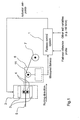
- Figures 1-4 illustrate the invention by showing how it can be applied for flatness control. What is shown in Figure 2 is generic.
- a flatness control system 1 is integrated in a system comprising a mill stand 2 having several actuators 3 and rolls 4.
- An uncoiler not shown, feeds a strip 5 to and through the mill stand 2, whereby the strip 5 passes a flatness measurement system 6 for example a "Stressometer” system, and is rolled up on a coiler 7.
- the mill stand 2 may control skewing, bending and/or shifting of the rolls 4. Thereby, they change the shape of the roll gap, which is where the strip 5 is affected as it passes between the rolls 4.
- the resulting product of the rolling process is a rolled strip 5 with desired flatness.
- the flatness control system 1 is designed comprising a number of advanced building blocks, as can be seen in Figure 3 , having all required functionalities.
- the method according to the invention involves selection of a model structure.
- the further steps of the invention are performed in either of two modes, tuning session 8 or adaptive control 9.
- excitation can be applied to the process and parameter estimation provides values for the otherwise unknown parameters, based on data from operation of the process.
- the process model With the model structure given, previously unknown parameters determined by estimation and known parameters and relations inserted, the process model is designed. Then, if there is any signal processing performed, the effect of it is also added to form a complete model. This complete model is used for the controller tuning, where any adequate model based method can be applied.
- the model determination and the model based tuning are repeated as new data becomes available with new sampling instants.
- a tuning session can be performed either in open loop, or with the controller in closed loop operation.
- the controller operates in closed loop, and tuning results are applied to the controller as they occur. Whether the control shall be active or not, and whether it shall be adaptive, is determined by programmed conditions and/or operator decisions.
- the block Controller 10 can be interpreted as either a multivariable controller or a number of single loop controllers. The latter case is described here, assuming the control task to be divided into a number of control loops equal to the number of mill actuators, each control loop with its own single-input-single-output controller.
- the controller outputs u(t) are fed to the actuators 3 or the actuator servos, not shown.
- the actuator movements affect the roll gap in the mill stand 2 and thereby the local properties p(t) of the strip just passing the roll gap.
- the measurement system 6 senses the tension distribution s(t) across the strip 5 via the measurement roll 11 at a position between the roll gap and the coiler 7. With a Stressometer system, s(t) is sampled four times per revolution of the measurement roll.
- the flatness measurement system 6 translates the raw measurement into a flatness profile z(t). This may involve filtering and re-sampling.
- the vector z(t) typically has a dimension between 16 and 64.
- the vector z(t) is compared with the flatness reference r(t) in order to produce a difference value, the flatness error e(t).
- This flatness error e(t) is mapped to the space of actuators to produce the so called parameterized error e p (t).
- the dimension of u(t) and e p (t) is less or equal to the number of mill actuators 3.
- the tuning involves injection of excitation signals added to the controller outputs and the use of gathered values of u(t) and e p (t) to estimate parameters of a model of the process for each control loop. In doing this, what is previously known about the process is used, so that only the unknown parameters need to be estimated. The estimated values of the unknown parameters are then used together with what was known before to form a complete model that describes the whole dynamics from controller output to controller input, so that it can be used to tune the controller with a model based tuning rule. The excitation signal is generated until the estimation of the parameters is sufficiently accurate.
- This tuning gives as a result the controller parameters to be used.
- the parameter estimation, the forming of a complete model and the tuning are performed for each control loop.
- the parameter estimation and tuning is performed on-line and the tuning result is also applied on-line to provide adaptive control. It is an advantage to have few parameters to estimate in adaptive control. It can be as few as one parameter per control loop, the process gain. Its true value may differ from coil to coil, but will be the same throughout the same coil. Therefore, adaptive control should be applied during the initial rolling of a coil, until the gain value has been found. After that, the excitation signal is cut off (set to zero), and no further estimation will be performed for that control loop, but the tuning rule will still be used to provide parameter scheduling, as the model will be updated with updated previous knowledge, such as rolling speed, filter transfer function and sampling period.
- the flowchart of Figure 4 discloses the sequence of steps that are executed repeatedly, for the example of a flatness control system based on the invention.
- the first action, described in block 12, is to get a flatness measurement from the measurement system 6.
- the measurement roll 11 gives in this case four measurements per revolution, and the measurement system 6 delivers a new, possibly filtered, measurement at either this rate or the rate down-sampled by an integer factor.
- the following action 13 is to form or determine the flatness error as the deviation from the flatness reference.
- the measurement is a vector, and it is subtracted from a corresponding reference vector to form the flatness error.
- the third step 14 is to form or determine the parameterized error, i.e. mapped to the space of control loops.
- the number of control loops is less than the dimension of the measurement vector, so the error is projected to the smaller dimension corresponding to the number of control loops, using the mill matrix, which models the strip deformation per controller output.
- a fourth step 15 is to update an on-line estimate of required model parameters. Using a continuous time model, some parts of the model and its structure can be treated as known, while a smaller number of parameters are estimated on-line as depicted in a separate figure.
- a further step 16 is to combine the parameter estimates with known parts to form a complete model.
- all is taken into account, i.e. estimated parameters, constant parameters treated as known, and also parameters that may vary in a known manner, such as production speed, sampling period, and measurement filtering (as parameter scheduling).
- Another step 17 is to apply a tuning rule to get updated controller tuning.
- Any appropriate model based tuning method can be applied.
- lambda tuning combined with model reduction to its required model form, first order plus deadtime, can be used.
- Inputs to the tuning are the final model and an adjustable parameter specifying the required tradeoff between performance and robustness.
- the seventh step 18 is to apply the control, i. e. calculate the controller output with the retuned controller acting on the parameterized error for this loop.
- the controller e. g. a PI controller
- the method steps 15 to 18 are repeated for each control loop and the method steps 16 and 17 can be skipped if there is no change in either of estimated parameters for the loop or parameters used for scheduling (speed, sampling period, measurement filter).
- the next step 19 is to remap from control loop space to actuator space if they differ. If the actuators are mapped to a lower number of control loops, the controller outputs are also remapped to the actual number of actuators.
- the next step 20 is to feed the controller outputs to the actuators or to the actuator servo setpoints. There are normally servos for each actuator, and in those cases the controller outputs are fed to these servos rather than directly to the actuators.
- the block scheme of Figure 5 illustrates the essential actions or steps of an example of implementation for recursive estimation of physical parameters in a continuous time dynamic model according to the invention.
- the process modeled has inputs that influence it and are available for control of it, and it has outputs. It can be part of a larger process, where this part has been selected to form a control loop together with the controller assigned to it, one loop of possibly many.
- the block scheme of Figure 5 shows activities performed when a new measurement becomes available. They need not necessarily be executed every sample, but can possibly be performed more seldom according to some criterion.
- One such criterion is indicated within the scheme, an adaptation deadzone 21, meaning that when there is too little information in the data, no parameter update will be performed.
- Measurements 22 are obtained at sampling instants, which may occur at any sampling rate, and the changes of the process input u are associated with these sampling instants.
- pairs of y and u are known in 23 for a number of instants back in time.
- Some of these samples of y and u are gathered in a regression vector ⁇ (t) to be used in a discrete time model to predict the present measurement y(t).
- the current model is formulated in continuous time, and some of its parameters may be treated as known, while others are to be estimated. At time t, the previous estimate of these parameters is the vector ⁇ (t-1).
- the complete continuous time process model is formed in a step 24 assuming that these estimates are the true values, and this model is converted to the required discrete time prediction model in a step 25, using the appropriate sampling period. In doing this, the effect of any measurement filter 26 is also taken into account.
- the prediction error ⁇ (t) is formed as the difference between the actual measurement and the prediction in a step 27.
- the gradient ⁇ T (t) of the prediction with respect to the estimated parameters is also needed. It can be derived analytically, or it can be obtained by numeric differentiation in a step 28. The latter approach means that predictions are calculated for a set of models where the estimated parameters are perturbed a little. The difference in the prediction divided by the perturbation in the parameter is an approximation of the required partial derivative with respect to that parameter.
- the outlier protection compares the size of the present prediction error with what it has been statistically and calculates a factor that reduces the effect of large errors substantially as in 29. See Figure 6 , which presents an example of this belief factor, f b .
- the function involves on-line estimation of the variance of the prediction errors, to compare the present size with. In a simple case, this variance estimation is performed just by low pass filtering the squared prediction errors.
- the prediction gradient ⁇ r (t) T and the prediction error ⁇ r (t), after possible reduction due to outlier detection or estimates tending outside the allowed area, are used to determine the direction and size of the parameter estimate update action 31.
- the one of forgetting is widely known. Whether it is implemented as uniform forgetting or directional forgetting or relies on a Kalman filter approach or addresses a target on the trace of P, can be a matter of taste. Related to the forgetting is also the risk of covariance wind-up. It can be counteracted by refraining from updating at all, when there is too little information, as will be the case when applying an appropriate adaptation deadzone.
- the steps to take in order to form the required discrete time parameter vector involve forming the continuous time model - based on the estimated parameters and what else is known - and then translating it to discrete time, in a well-known manner, and expressing the resulting model in transfer function form so that the parameters a 1 ... b 1 ... and k are obtained.
- the continuous time model is in this example K 1 + ⁇ ⁇ s ⁇ e - D 0 ⁇ s ⁇ e / v s - L
- L would probably be considered as a known parameter as well as the flow rate or speed, v.
- the corresponding discrete time model for the sampling period h is K ⁇ 1 - ⁇ + ⁇ - ⁇ ⁇ q - 1 1 - ⁇ ⁇ q - 1 ⁇ q - k
- ⁇ e - h / ⁇
- ⁇ e -( kh-D )/ ⁇
- D D 0 + / v L
- k is D h rounded to the nearest higher integer.
- the continuous time model would most conveniently be formulated as a state space model, which is converted first to a discrete time state space model, and then to transfer function form - still in accordance with the illustrating example above.
- the approach allows any combination of known and unknown parameters in the complete model. If, for example, there is a filter applied to the raw measurements to get the sampled values available for use in the identification, then that known filter would be accounted for in the derivation of the expressions for the parameters a 1 , ... b 1 ... .
- the required prediction gradient ⁇ T ( t ) can be derived analytically, especially for simple model structures. Alternatively, it can be obtained by numerical differentiation in the following way. A small deviation is introduced in each of the estimated parameters (elements of ⁇ ), one by one, and the prediction is calculated for each case. The resulting deviation in prediction is then divided by the parameter deviation, for each of the estimated parameters, to form the corresponding element of the gradient.
- the tuning of the controller is based on a model of the process. Also the effect of sampling, and in particular of filters applied to the measurement are taken into account. Any model based tuning method, suitable for the model and controller types used, could be applied.
- a very simple one is known as lambda tuning, aiming at a closed-loop system with specified time constant lambda ( ⁇ ). Often the user specifies the lambda factor, or slowdown factor, ⁇ f , rather than lambda itself.
- lambda tuning is only applicable to first order systems with or without deadtime. It can also be applied to a higher order model, after simplification of the model to order one.
- ⁇ f ( n f -1 ) T b / 2, where ⁇ b is the filter sampling period.
- lambda tuning is only mentioned as an example, and the method described in the invention is equally well applicable with other variants of model based tuning.
Landscapes
- Engineering & Computer Science (AREA)
- Physics & Mathematics (AREA)
- General Physics & Mathematics (AREA)
- Automation & Control Theory (AREA)
- Health & Medical Sciences (AREA)
- Artificial Intelligence (AREA)
- Computer Vision & Pattern Recognition (AREA)
- Evolutionary Computation (AREA)
- Medical Informatics (AREA)
- Software Systems (AREA)
- Feedback Control In General (AREA)
Claims (20)
- Verfahren zum Abstimmen einer Steuereinheit (10), die eine Eigenschaft (p(t)) eines Industrieprozesses mit einem variierenden, aber bekannten Materialdurchfluss steuert, wobei das Verfahren Folgendes umfasst:- Einkoppeln von Anregungssignalen, die dem Ausgangssignal (u(t)) der Steuereinheit hinzugefügt worden sind,- Empfangen von Messungen (z(t)) der Eigenschaft als Reaktion auf die Anregungssignale,- Wählen einer ersten Prozessmodellstruktur, die eine oder mehrere unbekannte Parameter enthält,- Schätzen des Werts des einen oder der mehreren unbekannten Parameter auf der Basis der Messungen (z(t)) der Eigenschaft und eines Ausgangssignals (u(t)) von der Steuereinheit, dadurch gekennzeichnet, dass das erste Prozessmodell zeitkontinuierlich ist und die Wirkung eines variierenden Materialdurchflusses beschreibt und dass ein oder mehrere unbekannte Parameter unabhängig von dem variierenden Materialdurchfluss sind, und wobei das Verfahren ferner Folgendes umfasst:- Berechnen eines zweiten Modells, das auf der Basis des ersten Prozessmodells, der geschätzten Werte des einen oder der mehreren unbekannten Parameter und der bekannten Parameter einschließlich des bekannten Materialdurchflusses die Dynamiken vom Ausgang der Steuereinheit zum Eingang der Steuereinheit beschreibt, und- Durchführen einer auf dem Modell basierenden Abstimmung der Steuereinheit auf der Basis des zweiten Modells.
- Verfahren nach Anspruch 1, wobei das Verfahren Folgendes umfasst:- Wählen einer Prozessmodellstruktur, die höchstens einen Modellparameter pro Eingangs-/Ausgangspaar umfasst, der durch Variieren einer tatsächlichen Verstärkung des Prozesses beeinflusst wird.
- Verfahren nach einem der vorhergehenden Ansprüche, wobei das Verfahren Folgendes umfasst:- Wählen einer Prozessmodellstruktur, die höchstens einen Modellparameter pro Aktuator umfasst, der durch variierende tatsächliche Reaktionszeiten der Aktuatoren beeinflusst wird.
- Verfahren nach einem der vorhergehenden Ansprüche, wobei das Verfahren Folgendes umfasst:- Einbeziehen in das Prozessmodell irgendwelcher Verzögerungen auf Grund der Datenverarbeitung und der Kommunikation,- Wählen der Prozessmodellstruktur derart, dass Variationen der Verzögerungen nicht mehr als einen Modellparameter pro Modelleingang beeinflussen.
- Verfahren nach einem der vorhergehenden Ansprüche, wobei das Verfahren Folgendes umfasst:- Zusammensetzen der Prozessmodellstruktur aus zwei Teilen, wobei der eine Teil das Transportverhalten beschreibt, bei dem mögliche Totzeiten und mögliche Zeitkonstanten zu dem Materialdurchfluss umgekehrt proportional sind, und der andere Teil unabhängig von dem Materialdurchfluss ist.
- Verfahren nach einem der vorhergehenden Ansprüche, wobei das Verfahren Folgendes umfasst:- Ableiten eines Modells erster Ordnung plus Totzeit für jeden Teil des Modells- Einführen eines Transportverhaltensparameters ξ, der den Grad der reinen Totzeit in Beziehung zur reinen Reaktion erster Ordnung des Transportverhaltens definiert,- Aufweisen der Totzeit, die durch die bekannte Entfernung Ld beschrieben ist, in dem Fall des reinen Transportverhaltens erster Ordnung,- Aufweisen der verbundenen Zeitkonstanten, die durch die bekannte Entfernung Lm beschrieben ist, in dem Fall des reinen Transportverhaltens erster Ordnung,
und- Schätzen der Parameterverstärkung (K) und/oder der flussunabhängigen Zeitkonstanten (τ) und/oder der flussunabhängigen Totzeit (D0) und/oder des Transportverhaltensparameters (ξ). - Verfahren nach einem der vorhergehenden Ansprüche, wobei das Verfahren Folgendes umfasst:- Wählen der Prozessmodellstruktur

- Verfahren nach einem der vorhergehenden Ansprüche, wobei das Verfahren Folgendes umfasst:- Schätzen von mindestens einem Parameter unter Verwendung eines Vorhersagefehlerverfahrens.
- Verfahren nach einem der vorhergehenden Ansprüche, wobei das Verfahren Folgendes umfasst:- Reduzieren der Parameteraktualisierungsgröße, wenn die unbeschränkte Aktualisierung einen Bereich außerhalb definierter zulässiger Parameterbereiche erreicht, aber Herstellen der Parameteraktualisierung in derselben Richtung in dem Parameterraum,- Anwenden desselben Reduktionsfaktors sowohl auf Regressoren als auch auf den Vorhersagefehler, der sowohl bei der Parameteraktualisierung als auch bei der Aktualisierung einer Matrix, die Informationen vorhält, die für eine rekursive Abschätzung notwendig sind, verwendet werden soll, und- dadurch Einhalten der Parameterschätzungen innerhalb der zulässigen Bereiche.
- Verfahren nach einem der vorhergehenden Ansprüche, wobei das Verfahren Folgendes umfasst:- Reduzieren der Wirkung der Messungen und Regressoren gemäß einem Glaubensfaktor, der aus dem Verhältnis zwischen Vorhersagefehlergröße und geschätzter Standardabweichung von vorherigen Vorhersagefehlern berechnet wird, für den Fall großer Vorhersagefehler,- dadurch Erreichen eines Schutzes gegen Sonderfälle.
- Verfahren nach einem der vorhergehenden Ansprüche, wobei das Verfahren Folgendes umfasst:- Abtasten der Prozessausgabewerte mit einer Basisabtastrate, Anwenden eines Filters mit derselben Abtastrate und erneutes Abtasten mit einer geringeren Abtastrate, wobei diese Rate für die Protokollierung von Werten aus dem Prozessbetrieb verwendet wird, und Einbeziehen der Wirkung dieses Abtastens, Filterns und erneuten Abtastens in die Vorhersageberechnungen und Aktualisierungen von Parameterschätzungen.
- Verfahren nach einem der vorhergehenden Ansprüche, wobei das Verfahren Folgendes umfasst:- Durchführen eines Identifikationsexperiments, das besagt, den Prozess mit einer beabsichtigten Anregung, die mindestens eine manipulierte Variable beeinflusst, zu betreiben,- Schätzen von mindestens einem Parameter online während des Identifikationsexperiments.
- Verfahren nach einem der vorhergehenden Ansprüche, wobei das Verfahren Folgendes umfasst:- Berechnen der modellbasierten Abstimmung der Steuereinheit online.
- Verfahren nach einem der vorhergehenden Ansprüche, wobei das Verfahren Folgendes umfasst:- Darstellen der Ergebnisse für einen Anwender in Echtzeit,- dadurch Ermöglichen einer Anwenderentscheidung, das Identifikationsexperiment zu beenden, sobald zufrieden stellende Ergebnisse erzielt worden sind.
- Verfahren nach einem der vorhergehenden Ansprüche, wobei das Verfahren Folgendes umfasst:- Schätzen von mindestens einem Parameter online während des Prozessbetriebs und während des Steuerns mit der Steuereinheit,- Durchführen der modellbasierten Abstimmungsberechnungen für die Steuereinheit online,- Anwenden des Abstimmungsergebnisses auf die Steuereinheit online,- dadurch Erreichen einer echten anpassungsfähigen Steuerung.
- Verfahren nach einem der vorhergehenden Ansprüche, wobei das Verfahren Folgendes umfasst:- Schätzen von weniger Parametern während des Betriebs mit einer Online-Aktualisierung der Steuereinheit als während des Identifikationsexperiments,- Ermöglichen, dass das Ergebnis der Parameterschätzung aus dem Identifikationsexperiment den Wert von mindestens einem Parameter definiert, und Behandeln dieses Parameters oder dieser Parameter als bekannte Parameter während des Betriebs mit einer Online-Aktualisierung der Steuereinheit.
- Verfahren nach einem der vorhergehenden Ansprüche, wobei das Verfahren Folgendes umfasst:- Verwenden einer Lambda-Abstimmung oder IMC-Abstimmung als modellbasiertes Abstimmungsverfahren für die Steuereinheit.
- Vorrichtung zum Abstimmen einer Steuereinheit (10), die eine Eigenschaft (p(t)) eines Industrieprozesses mit einem variierenden, aber bekannten Materialdurchfluss steuert, wobei die Vorrichtung Folgendes umfasst:- eine Addiereinrichtung (10b) zum Hinzufügen von Anregungssignalen zu dem Ausgangssignal (u(t)) der Steuereinheit,- ein Messsystem (6) zum Messen der Eigenschaft als Reaktion auf die Anregungssignale, und- eine modellbasierte Abstimmungseinheit (10c), die dafür ausgelegt ist, auf der Basis der Messungen (z(t)) der Eigenschaft und des Ausgangssignals (u(t)) von der Steuereinheit den Wert von einem oder mehreren unbekannten Parametern einer Prozessmodellstruktur zu schätzen, dadurch gekennzeichnet, dass die modellbasierte Abstimmungseinheit dafür ausgelegt ist, den Wert von einem oder mehreren Parametern mit unbekannten Werten einer ersten Prozessmodellstruktur, die zeitkontinuierlich ist und die Wirkung eines variierenden Materialdurchflusses beschreibt, zu schätzen und wobei der eine oder die mehreren unbekannten Parameter unabhängig von dem variierenden Materialdurchfluss sind, und ein Modell zu berechnen, das auf der Basis des ersten Prozessmodells, der geschätzten Werte des einen oder der mehreren unbekannten Parameter und der bekannten Parameter einschließlich des bekannten Materialdurchflusses die Dynamiken vom Ausgang der Steuereinheit zum Eingang der Steuereinheit beschreibt, und auf der Basis des zweiten Modells eine modellbasierte Abstimmung der Steuereinheit durchzuführen.
- Computerprogrammprodukt, das direkt in den internen Speicher eines Computers geladen werden kann und das Software umfasst, um die Schritte eines Verfahrens nach einem der Ansprüche 1 bis 17 auszuführen.
- Computerlesbares Medium mit einem darauf aufgezeichneten Programm, wobei das Programm einen Computer veranlasst, die Schritte nach einem der Ansprüche 1 bis 17 durchzuführen, wenn das Programm auf dem Computer läuft.
Applications Claiming Priority (3)
| Application Number | Priority Date | Filing Date | Title |
|---|---|---|---|
| SE0502956 | 2005-12-30 | ||
| SE0600321A SE529454C2 (sv) | 2005-12-30 | 2006-02-07 | Förfarande och anordning för trimning och styrning |
| PCT/SE2006/050591 WO2007078246A1 (en) | 2005-12-30 | 2006-12-18 | Method and device for tuning and control |
Publications (3)
| Publication Number | Publication Date |
|---|---|
| EP1966655A1 EP1966655A1 (de) | 2008-09-10 |
| EP1966655A4 EP1966655A4 (de) | 2010-04-28 |
| EP1966655B1 true EP1966655B1 (de) | 2013-11-06 |
Family
ID=38228509
Family Applications (1)
| Application Number | Title | Priority Date | Filing Date |
|---|---|---|---|
| EP06835945.4A Not-in-force EP1966655B1 (de) | 2005-12-30 | 2006-12-18 | Verfahren und vorrichtung für einstellung und steuerung |
Country Status (7)
| Country | Link |
|---|---|
| US (1) | US7937165B2 (de) |
| EP (1) | EP1966655B1 (de) |
| JP (1) | JP4859931B2 (de) |
| CN (1) | CN101346676B (de) |
| ES (1) | ES2444692T3 (de) |
| SE (1) | SE529454C2 (de) |
| WO (1) | WO2007078246A1 (de) |
Families Citing this family (26)
| Publication number | Priority date | Publication date | Assignee | Title |
|---|---|---|---|---|
| SE529074C2 (sv) * | 2005-06-08 | 2007-04-24 | Abb Ab | Förfarande och anordning för optimering av planhetsstyrning vid valsning av ett band |
| KR101531416B1 (ko) * | 2007-09-13 | 2015-06-24 | 옵티스 셀룰러 테크놀로지, 엘엘씨 | 상향링크 신호 전송 방법 |
| EP2110722A1 (de) * | 2008-04-17 | 2009-10-21 | Siemens Aktiengesellschaft | System zur Simulation automatisierungstechnischer Anlagen |
| DE102008035639A1 (de) * | 2008-07-31 | 2010-02-04 | Robert Bosch Gmbh | Verfahren zur Modellierung eines Regelkreises für eine Bearbeitungsmaschine |
| DE102009019642A1 (de) * | 2009-04-30 | 2010-11-04 | Volkswagen Ag | Einrichtung zur Betätigung einer hydraulischen Kupplung eines Kraftfahrzeugs und Montageverfahren dazu |
| DE102009048951A1 (de) * | 2009-10-10 | 2011-04-14 | Robert Bosch Gmbh | Verfahren zur Modellierung eines Seitenregister-Regelkreises für eine Bearbeitungsmaschine |
| CN101882796B (zh) * | 2010-06-02 | 2013-03-27 | 马鞍山钢铁股份有限公司 | 一种高速线材轧机抛尾速升机械动能回馈速率的控制方法 |
| TWI454868B (zh) * | 2012-11-02 | 2014-10-01 | Ind Tech Res Inst | 目標導向數值控制自動調校系統與方法 |
| RU2500009C1 (ru) * | 2012-12-13 | 2013-11-27 | Федеральное государственное бюджетное образовательное учреждение высшего профессионального образования "Ростовский государственный строительный университет", РГСУ | Адаптивная система терминального управления |
| US10324424B2 (en) | 2013-03-11 | 2019-06-18 | Johnson Controls Technology Company | Control system with response time estimation and automatic operating parameter adjustment |
| US9395708B2 (en) | 2013-03-11 | 2016-07-19 | Johnson Controls Technology Company | Systems and methods for adaptive sampling rate adjustment |
| ES2618487T3 (es) * | 2013-03-25 | 2017-06-21 | Abb Schweiz Ag | Procedimiento y sistema de control para ajustar el control de planicidad en un laminador |
| US9507344B2 (en) * | 2013-05-10 | 2016-11-29 | Honeywell International Inc. | Index generation and embedded fusion for controller performance monitoring |
| EP3252548B1 (de) * | 2016-06-03 | 2021-11-17 | Johnson Controls Technology Company | Steuerungssystem mit antwortzeitschätzung und automatischer betriebsparametereinstellung |
| WO2017211966A1 (en) | 2016-06-10 | 2017-12-14 | Abb Schweiz Ag | A robust automatic method to identify physical parameters of a mechanical load with integrated reliability indication |
| DE102016222732A1 (de) * | 2016-11-18 | 2018-05-24 | Robert Bosch Gmbh | Verfahren und Vorrichtung zum Durchführen einer Positionsregelung für eine Stellgebereinheit |
| US20180161839A1 (en) * | 2016-12-09 | 2018-06-14 | Honeywell International Inc. | Metal thickness control model based inferential sensor |
| US11467543B2 (en) * | 2019-09-20 | 2022-10-11 | Fisher-Rosemount Systems, Inc. | Process controller design with process approximation and lambda tuning |
| TWI742502B (zh) * | 2019-12-31 | 2021-10-11 | 鍾國誠 | 用於控制可變物理參數的控制裝置及方法 |
| TWI741471B (zh) * | 2019-12-31 | 2021-10-01 | 鍾國誠 | 控制目標裝置及用於控制可變物理參數的方法 |
| TWI775592B (zh) * | 2019-12-31 | 2022-08-21 | 鍾國誠 | 用於控制照明裝置的控制裝置及方法 |
| TWI734335B (zh) * | 2019-12-31 | 2021-07-21 | 鍾國誠 | 用於控制可變物理參數的控制裝置及方法 |
| TWI734334B (zh) * | 2019-12-31 | 2021-07-21 | 鍾國誠 | 控制目標裝置及用於控制可變物理參數的方法 |
| CN115483993A (zh) * | 2021-06-15 | 2022-12-16 | 中兴通讯股份有限公司 | 检测输入信号对输出信号影响的方法、装置、设备和介质 |
| CN113552805B (zh) * | 2021-08-12 | 2022-12-27 | 南京理工大学 | 一种电静液作动器的间接自适应鲁棒控制方法 |
| CN113867134B (zh) * | 2021-11-05 | 2023-12-01 | 国家石油天然气管网集团有限公司 | 一种基于可编程逻辑控制器的pid控制死区调节方法 |
Citations (1)
| Publication number | Priority date | Publication date | Assignee | Title |
|---|---|---|---|---|
| WO2001079945A1 (en) * | 2000-04-06 | 2001-10-25 | Abb Automation Inc. | System and methodology for adaptive, linear model predictive control based on rigorous, nonlinear process model |
Family Cites Families (24)
| Publication number | Priority date | Publication date | Assignee | Title |
|---|---|---|---|---|
| US3852578A (en) * | 1970-02-03 | 1974-12-03 | Industrial Nucleonics Corp | Control system and method for machine or process having dead time |
| US4006346A (en) * | 1975-11-13 | 1977-02-01 | Phillips Petroleum Company | Control method including feedforward signal |
| US4277832A (en) * | 1979-10-01 | 1981-07-07 | General Electric Company | Fluid flow control system |
| US4882784A (en) * | 1987-11-04 | 1989-11-21 | Moksnes Manufacturing Co., Inc. | Loss-in-weight feeder system |
| US4814968A (en) * | 1987-10-19 | 1989-03-21 | Fischer & Porter Company | Self-tuning process controller |
| US5122963A (en) * | 1990-03-07 | 1992-06-16 | Process Automation Business, Inc. | Actuation cell response and mapping determinations for web forming machines |
| US5260865A (en) * | 1991-04-01 | 1993-11-09 | Beauford Martin H | Nonlinear model based distillation control |
| US5367260A (en) * | 1992-10-15 | 1994-11-22 | Auburn International, Inc. | Apparatus to obtain flow rates (melt index) in plastics via fixed frequency, pulsed NMR |
| US5539634A (en) * | 1993-09-03 | 1996-07-23 | Measurex Corporation | Sheetmaking system identification using synthetic measurement produced from redundant noisy measurements |
| US5682309A (en) * | 1995-04-28 | 1997-10-28 | Exxon Chemical Patents Inc. | Feedback method for controlling non-linear processes |
| US5691896A (en) * | 1995-08-15 | 1997-11-25 | Rosemount, Inc. | Field based process control system with auto-tuning |
| US6539267B1 (en) * | 1996-03-28 | 2003-03-25 | Rosemount Inc. | Device in a process system for determining statistical parameter |
| US5818714A (en) * | 1996-08-01 | 1998-10-06 | Rosemount, Inc. | Process control system with asymptotic auto-tuning |
| US6055524A (en) * | 1997-10-06 | 2000-04-25 | General Cybernation Group, Inc. | Model-free adaptive process control |
| US6080278A (en) * | 1998-01-27 | 2000-06-27 | Honeywell-Measurex Corporation | Fast CD and MD control in a sheetmaking machine |
| US6381505B1 (en) * | 1998-09-28 | 2002-04-30 | Aspen Technology, Inc. | Robust steady-state target calculation for model predictive control |
| FI111106B (fi) * | 1999-02-19 | 2003-05-30 | Neles Controls Oy | Menetelmä prosessinsäätösilmukan virittämiseksi teollisuusprosessissa |
| AU2001247336B2 (en) * | 2000-03-10 | 2006-02-02 | Smiths Detection, Inc. | Control for an industrial process using one or more multidimensional variables |
| FI114947B (fi) * | 2002-09-13 | 2005-01-31 | Metso Automation Oy | Menetelmä ja laitteisto prosessissa olevan prosessilaitteen hystereesin määrittämiseksi |
| KR100642373B1 (ko) * | 2003-06-30 | 2006-11-10 | 지멘스 악티엔게젤샤프트 | 진동 자이로스코프를 포함하는 회전 속도 센서 및 그 회전 속도 센서를 이퀄라이징하는 방법 |
| US7197485B2 (en) * | 2003-07-16 | 2007-03-27 | United Technologies Corporation | Square root method for computationally efficient model predictive control |
| SE527168C2 (sv) * | 2003-12-31 | 2006-01-10 | Abb Ab | Förfarande och anordning för mätning, bestämning och styrning av planhet hos ett metallband |
| FR2879486B1 (fr) * | 2004-12-22 | 2007-04-13 | Vai Clecim Sa | Regulation de la planeite d'une bande metallique a la sortie d'une cage de laminoir |
| US7840287B2 (en) * | 2006-04-13 | 2010-11-23 | Fisher-Rosemount Systems, Inc. | Robust process model identification in model based control techniques |
-
2006
- 2006-02-07 SE SE0600321A patent/SE529454C2/sv not_active IP Right Cessation
- 2006-12-18 EP EP06835945.4A patent/EP1966655B1/de not_active Not-in-force
- 2006-12-18 US US12/159,488 patent/US7937165B2/en active Active
- 2006-12-18 JP JP2008548470A patent/JP4859931B2/ja not_active Expired - Fee Related
- 2006-12-18 CN CN200680049429.3A patent/CN101346676B/zh not_active Expired - Fee Related
- 2006-12-18 WO PCT/SE2006/050591 patent/WO2007078246A1/en not_active Ceased
- 2006-12-18 ES ES06835945.4T patent/ES2444692T3/es active Active
Patent Citations (1)
| Publication number | Priority date | Publication date | Assignee | Title |
|---|---|---|---|---|
| WO2001079945A1 (en) * | 2000-04-06 | 2001-10-25 | Abb Automation Inc. | System and methodology for adaptive, linear model predictive control based on rigorous, nonlinear process model |
Also Published As
| Publication number | Publication date |
|---|---|
| ES2444692T3 (es) | 2014-02-26 |
| JP4859931B2 (ja) | 2012-01-25 |
| US7937165B2 (en) | 2011-05-03 |
| SE0600321L (sv) | 2007-07-01 |
| SE529454C2 (sv) | 2007-08-14 |
| JP2009522108A (ja) | 2009-06-11 |
| EP1966655A4 (de) | 2010-04-28 |
| CN101346676A (zh) | 2009-01-14 |
| US20090138102A1 (en) | 2009-05-28 |
| CN101346676B (zh) | 2011-02-09 |
| WO2007078246A1 (en) | 2007-07-12 |
| EP1966655A1 (de) | 2008-09-10 |
Similar Documents
| Publication | Publication Date | Title |
|---|---|---|
| EP1966655B1 (de) | Verfahren und vorrichtung für einstellung und steuerung | |
| Choi et al. | Looper and tension control in hot rolling mills: A survey | |
| Visioli | Research trends for PID controllers | |
| DE102004058238B4 (de) | Adaptive, multivariable Prozesssteuerung, die Modellschaltung und Attribut-Interpolation nutzt | |
| DE69122313T2 (de) | Auf variablem Horizont basierende adaptive Steuerung mit Mitteln zur Minimierung der Betriebskosten | |
| WO2007050692A2 (en) | Automated tuning of large-scale multivariable model predictive controllers for spatially-distributed processes | |
| EP2751628B1 (de) | Vorrichtung und verfahren zur vorhersage einer wicklung und zur verbesserung der prozessführung in einem industriellen prozesssteuersystem | |
| Asano et al. | Hot strip mill tension–looper control based on decentralization and coordination | |
| CN111132773B (zh) | 使用优化器的平整度控制 | |
| Bemporad et al. | Optimization-based automatic flatness control in cold tandem rolling | |
| JP2008543566A (ja) | ストリップの圧延工程における平坦度制御を最適化するための方法と装置 | |
| EP3296821A2 (de) | Regelkreisparameteridentifizierungsverfahren für modellbasierte industrielle prozesssteuergeräte | |
| Stephens et al. | On-line adaptive control in the hot rolling of steel | |
| JP2024178909A (ja) | 金属圧延機のためのモデルベースの多変量予測制御 | |
| Arkun et al. | A novel approach to full CD profile control of sheet-forming processes using adaptive PCA and reduced-order IMC design | |
| Butte et al. | Engineering process control: a review | |
| JP4474555B2 (ja) | Pid制御装置及びpid制御方法 | |
| Kim et al. | Sensitivity analysis on a neural network for analyzing the camber in hot rolling process | |
| Reeve et al. | Control, automation and the hot rolling of steel | |
| Bai et al. | Impact of model structure on the performance of dynamic data reconciliation | |
| Pittner et al. | Advanced Control | |
| Nguyen et al. | An internal model-based PID control for smart shot peening operation | |
| Ammar | Model identification of a paper machine cross-directional process under model predictive control | |
| Asano et al. | Parameter estimation for the tension model in hot strip mills | |
| Schaefer et al. | Evaluation of a NMPC Flowrate Controller for a Hot Rolling Finishing Mill for Steel Bars |
Legal Events
| Date | Code | Title | Description |
|---|---|---|---|
| PUAI | Public reference made under article 153(3) epc to a published international application that has entered the european phase |
Free format text: ORIGINAL CODE: 0009012 |
|
| 17P | Request for examination filed |
Effective date: 20080509 |
|
| AK | Designated contracting states |
Kind code of ref document: A1 Designated state(s): AT BE BG CH CY CZ DE DK EE ES FI FR GB GR HU IE IS IT LI LT LU LV MC NL PL PT RO SE SI SK TR |
|
| A4 | Supplementary search report drawn up and despatched |
Effective date: 20100331 |
|
| 17Q | First examination report despatched |
Effective date: 20100602 |
|
| DAX | Request for extension of the european patent (deleted) | ||
| GRAP | Despatch of communication of intention to grant a patent |
Free format text: ORIGINAL CODE: EPIDOSNIGR1 |
|
| INTG | Intention to grant announced |
Effective date: 20130725 |
|
| GRAS | Grant fee paid |
Free format text: ORIGINAL CODE: EPIDOSNIGR3 |
|
| GRAA | (expected) grant |
Free format text: ORIGINAL CODE: 0009210 |
|
| AK | Designated contracting states |
Kind code of ref document: B1 Designated state(s): AT BE BG CH CY CZ DE DK EE ES FI FR GB GR HU IE IS IT LI LT LU LV MC NL PL PT RO SE SI SK TR |
|
| REG | Reference to a national code |
Ref country code: GB Ref legal event code: FG4D |
|
| REG | Reference to a national code |
Ref country code: CH Ref legal event code: EP |
|
| REG | Reference to a national code |
Ref country code: AT Ref legal event code: REF Ref document number: 639871 Country of ref document: AT Kind code of ref document: T Effective date: 20131215 |
|
| REG | Reference to a national code |
Ref country code: IE Ref legal event code: FG4D |
|
| REG | Reference to a national code |
Ref country code: DE Ref legal event code: R096 Ref document number: 602006039194 Country of ref document: DE Effective date: 20140102 |
|
| REG | Reference to a national code |
Ref country code: ES Ref legal event code: FG2A Ref document number: 2444692 Country of ref document: ES Kind code of ref document: T3 Effective date: 20140226 |
|
| REG | Reference to a national code |
Ref country code: NL Ref legal event code: VDEP Effective date: 20131106 |
|
| REG | Reference to a national code |
Ref country code: LT Ref legal event code: MG4D |
|
| PG25 | Lapsed in a contracting state [announced via postgrant information from national office to epo] |
Ref country code: NL Free format text: LAPSE BECAUSE OF FAILURE TO SUBMIT A TRANSLATION OF THE DESCRIPTION OR TO PAY THE FEE WITHIN THE PRESCRIBED TIME-LIMIT Effective date: 20131106 Ref country code: LT Free format text: LAPSE BECAUSE OF FAILURE TO SUBMIT A TRANSLATION OF THE DESCRIPTION OR TO PAY THE FEE WITHIN THE PRESCRIBED TIME-LIMIT Effective date: 20131106 Ref country code: FI Free format text: LAPSE BECAUSE OF FAILURE TO SUBMIT A TRANSLATION OF THE DESCRIPTION OR TO PAY THE FEE WITHIN THE PRESCRIBED TIME-LIMIT Effective date: 20131106 Ref country code: IS Free format text: LAPSE BECAUSE OF FAILURE TO SUBMIT A TRANSLATION OF THE DESCRIPTION OR TO PAY THE FEE WITHIN THE PRESCRIBED TIME-LIMIT Effective date: 20140306 Ref country code: SE Free format text: LAPSE BECAUSE OF FAILURE TO SUBMIT A TRANSLATION OF THE DESCRIPTION OR TO PAY THE FEE WITHIN THE PRESCRIBED TIME-LIMIT Effective date: 20131106 |
|
| PG25 | Lapsed in a contracting state [announced via postgrant information from national office to epo] |
Ref country code: LV Free format text: LAPSE BECAUSE OF FAILURE TO SUBMIT A TRANSLATION OF THE DESCRIPTION OR TO PAY THE FEE WITHIN THE PRESCRIBED TIME-LIMIT Effective date: 20131106 |
|
| PG25 | Lapsed in a contracting state [announced via postgrant information from national office to epo] |
Ref country code: PT Free format text: LAPSE BECAUSE OF FAILURE TO SUBMIT A TRANSLATION OF THE DESCRIPTION OR TO PAY THE FEE WITHIN THE PRESCRIBED TIME-LIMIT Effective date: 20140306 |
|
| PG25 | Lapsed in a contracting state [announced via postgrant information from national office to epo] |
Ref country code: EE Free format text: LAPSE BECAUSE OF FAILURE TO SUBMIT A TRANSLATION OF THE DESCRIPTION OR TO PAY THE FEE WITHIN THE PRESCRIBED TIME-LIMIT Effective date: 20131106 |
|
| REG | Reference to a national code |
Ref country code: DE Ref legal event code: R097 Ref document number: 602006039194 Country of ref document: DE |
|
| PG25 | Lapsed in a contracting state [announced via postgrant information from national office to epo] |
Ref country code: CZ Free format text: LAPSE BECAUSE OF FAILURE TO SUBMIT A TRANSLATION OF THE DESCRIPTION OR TO PAY THE FEE WITHIN THE PRESCRIBED TIME-LIMIT Effective date: 20131106 Ref country code: PL Free format text: LAPSE BECAUSE OF FAILURE TO SUBMIT A TRANSLATION OF THE DESCRIPTION OR TO PAY THE FEE WITHIN THE PRESCRIBED TIME-LIMIT Effective date: 20131106 Ref country code: MC Free format text: LAPSE BECAUSE OF FAILURE TO SUBMIT A TRANSLATION OF THE DESCRIPTION OR TO PAY THE FEE WITHIN THE PRESCRIBED TIME-LIMIT Effective date: 20131106 Ref country code: SK Free format text: LAPSE BECAUSE OF FAILURE TO SUBMIT A TRANSLATION OF THE DESCRIPTION OR TO PAY THE FEE WITHIN THE PRESCRIBED TIME-LIMIT Effective date: 20131106 Ref country code: RO Free format text: LAPSE BECAUSE OF FAILURE TO SUBMIT A TRANSLATION OF THE DESCRIPTION OR TO PAY THE FEE WITHIN THE PRESCRIBED TIME-LIMIT Effective date: 20131106 |
|
| PLBE | No opposition filed within time limit |
Free format text: ORIGINAL CODE: 0009261 |
|
| STAA | Information on the status of an ep patent application or granted ep patent |
Free format text: STATUS: NO OPPOSITION FILED WITHIN TIME LIMIT |
|
| REG | Reference to a national code |
Ref country code: IE Ref legal event code: MM4A |
|
| PG25 | Lapsed in a contracting state [announced via postgrant information from national office to epo] |
Ref country code: DK Free format text: LAPSE BECAUSE OF FAILURE TO SUBMIT A TRANSLATION OF THE DESCRIPTION OR TO PAY THE FEE WITHIN THE PRESCRIBED TIME-LIMIT Effective date: 20131106 |
|
| 26N | No opposition filed |
Effective date: 20140807 |
|
| PG25 | Lapsed in a contracting state [announced via postgrant information from national office to epo] |
Ref country code: IE Free format text: LAPSE BECAUSE OF NON-PAYMENT OF DUE FEES Effective date: 20131218 |
|
| REG | Reference to a national code |
Ref country code: DE Ref legal event code: R097 Ref document number: 602006039194 Country of ref document: DE Effective date: 20140807 |
|
| PG25 | Lapsed in a contracting state [announced via postgrant information from national office to epo] |
Ref country code: SI Free format text: LAPSE BECAUSE OF FAILURE TO SUBMIT A TRANSLATION OF THE DESCRIPTION OR TO PAY THE FEE WITHIN THE PRESCRIBED TIME-LIMIT Effective date: 20131106 |
|
| PG25 | Lapsed in a contracting state [announced via postgrant information from national office to epo] |
Ref country code: CY Free format text: LAPSE BECAUSE OF FAILURE TO SUBMIT A TRANSLATION OF THE DESCRIPTION OR TO PAY THE FEE WITHIN THE PRESCRIBED TIME-LIMIT Effective date: 20131106 |
|
| PG25 | Lapsed in a contracting state [announced via postgrant information from national office to epo] |
Ref country code: BG Free format text: LAPSE BECAUSE OF FAILURE TO SUBMIT A TRANSLATION OF THE DESCRIPTION OR TO PAY THE FEE WITHIN THE PRESCRIBED TIME-LIMIT Effective date: 20131106 Ref country code: HU Free format text: LAPSE BECAUSE OF FAILURE TO SUBMIT A TRANSLATION OF THE DESCRIPTION OR TO PAY THE FEE WITHIN THE PRESCRIBED TIME-LIMIT; INVALID AB INITIO Effective date: 20061218 Ref country code: LU Free format text: LAPSE BECAUSE OF NON-PAYMENT OF DUE FEES Effective date: 20131218 |
|
| PG25 | Lapsed in a contracting state [announced via postgrant information from national office to epo] |
Ref country code: GR Free format text: LAPSE BECAUSE OF NON-PAYMENT OF DUE FEES Effective date: 20131106 |
|
| REG | Reference to a national code |
Ref country code: FR Ref legal event code: PLFP Year of fee payment: 10 |
|
| PG25 | Lapsed in a contracting state [announced via postgrant information from national office to epo] |
Ref country code: GR Free format text: LAPSE BECAUSE OF FAILURE TO SUBMIT A TRANSLATION OF THE DESCRIPTION OR TO PAY THE FEE WITHIN THE PRESCRIBED TIME-LIMIT Effective date: 20140207 |
|
| REG | Reference to a national code |
Ref country code: FR Ref legal event code: PLFP Year of fee payment: 11 |
|
| REG | Reference to a national code |
Ref country code: FR Ref legal event code: PLFP Year of fee payment: 12 |
|
| PGFP | Annual fee paid to national office [announced via postgrant information from national office to epo] |
Ref country code: TR Payment date: 20171215 Year of fee payment: 12 |
|
| REG | Reference to a national code |
Ref country code: GB Ref legal event code: 732E Free format text: REGISTERED BETWEEN 20180327 AND 20180328 |
|
| REG | Reference to a national code |
Ref country code: BE Ref legal event code: PD Owner name: ABB SCHWEIZ AG; CH Free format text: DETAILS ASSIGNMENT: CHANGE OF OWNER(S), CESSION; FORMER OWNER NAME: ABB AB Effective date: 20180323 |
|
| REG | Reference to a national code |
Ref country code: DE Ref legal event code: R081 Ref document number: 602006039194 Country of ref document: DE Owner name: ABB SCHWEIZ AG, CH Free format text: FORMER OWNER: ABB AB, VAESTERAS, SE |
|
| REG | Reference to a national code |
Ref country code: CH Ref legal event code: PUE Owner name: ABB SCHWEIZ AG, CH Free format text: FORMER OWNER: ABB AB, SE |
|
| REG | Reference to a national code |
Ref country code: ES Ref legal event code: PC2A Owner name: ABB SCHWEIZ AG. Effective date: 20180522 Ref country code: ES Ref legal event code: PC2A Effective date: 20180522 |
|
| REG | Reference to a national code |
Ref country code: AT Ref legal event code: PC Ref document number: 639871 Country of ref document: AT Kind code of ref document: T Owner name: ABB SCHWEIZ AG, CH Effective date: 20180507 |
|
| REG | Reference to a national code |
Ref country code: FR Ref legal event code: TP Owner name: ABB SCHWEIZ AG, CH Effective date: 20181106 |
|
| PGFP | Annual fee paid to national office [announced via postgrant information from national office to epo] |
Ref country code: FR Payment date: 20191220 Year of fee payment: 14 Ref country code: BE Payment date: 20191219 Year of fee payment: 14 |
|
| PGFP | Annual fee paid to national office [announced via postgrant information from national office to epo] |
Ref country code: CH Payment date: 20191219 Year of fee payment: 14 Ref country code: AT Payment date: 20191220 Year of fee payment: 14 |
|
| PGFP | Annual fee paid to national office [announced via postgrant information from national office to epo] |
Ref country code: ES Payment date: 20200121 Year of fee payment: 14 Ref country code: GB Payment date: 20191220 Year of fee payment: 14 |
|
| REG | Reference to a national code |
Ref country code: CH Ref legal event code: PL |
|
| REG | Reference to a national code |
Ref country code: AT Ref legal event code: MM01 Ref document number: 639871 Country of ref document: AT Kind code of ref document: T Effective date: 20201218 |
|
| GBPC | Gb: european patent ceased through non-payment of renewal fee |
Effective date: 20201218 |
|
| REG | Reference to a national code |
Ref country code: BE Ref legal event code: MM Effective date: 20201231 |
|
| PG25 | Lapsed in a contracting state [announced via postgrant information from national office to epo] |
Ref country code: FR Free format text: LAPSE BECAUSE OF NON-PAYMENT OF DUE FEES Effective date: 20201231 Ref country code: AT Free format text: LAPSE BECAUSE OF NON-PAYMENT OF DUE FEES Effective date: 20201218 |
|
| PG25 | Lapsed in a contracting state [announced via postgrant information from national office to epo] |
Ref country code: LI Free format text: LAPSE BECAUSE OF NON-PAYMENT OF DUE FEES Effective date: 20201231 Ref country code: CH Free format text: LAPSE BECAUSE OF NON-PAYMENT OF DUE FEES Effective date: 20201231 Ref country code: GB Free format text: LAPSE BECAUSE OF NON-PAYMENT OF DUE FEES Effective date: 20201218 |
|
| REG | Reference to a national code |
Ref country code: ES Ref legal event code: FD2A Effective date: 20220221 |
|
| PG25 | Lapsed in a contracting state [announced via postgrant information from national office to epo] |
Ref country code: ES Free format text: LAPSE BECAUSE OF NON-PAYMENT OF DUE FEES Effective date: 20201219 |
|
| PG25 | Lapsed in a contracting state [announced via postgrant information from national office to epo] |
Ref country code: TR Free format text: LAPSE BECAUSE OF NON-PAYMENT OF DUE FEES Effective date: 20201218 |
|
| PG25 | Lapsed in a contracting state [announced via postgrant information from national office to epo] |
Ref country code: BE Free format text: LAPSE BECAUSE OF NON-PAYMENT OF DUE FEES Effective date: 20201231 |
|
| PGFP | Annual fee paid to national office [announced via postgrant information from national office to epo] |
Ref country code: IT Payment date: 20231228 Year of fee payment: 18 Ref country code: DE Payment date: 20231214 Year of fee payment: 18 |
|
| REG | Reference to a national code |
Ref country code: DE Ref legal event code: R119 Ref document number: 602006039194 Country of ref document: DE |
|
| PG25 | Lapsed in a contracting state [announced via postgrant information from national office to epo] |
Ref country code: DE Free format text: LAPSE BECAUSE OF NON-PAYMENT OF DUE FEES Effective date: 20250701 |
|
| PG25 | Lapsed in a contracting state [announced via postgrant information from national office to epo] |
Ref country code: IT Free format text: LAPSE BECAUSE OF NON-PAYMENT OF DUE FEES Effective date: 20241218 |