EP1966861B1 - Verfahren zum aufbringen einer kabelmuffe auf einen stützelement und vorrichtung zur durchführung des verfahrens - Google Patents
Verfahren zum aufbringen einer kabelmuffe auf einen stützelement und vorrichtung zur durchführung des verfahrens Download PDFInfo
- Publication number
- EP1966861B1 EP1966861B1 EP05850985.2A EP05850985A EP1966861B1 EP 1966861 B1 EP1966861 B1 EP 1966861B1 EP 05850985 A EP05850985 A EP 05850985A EP 1966861 B1 EP1966861 B1 EP 1966861B1
- Authority
- EP
- European Patent Office
- Prior art keywords
- sleeve
- tubular
- radially
- expanders
- supporting element
- Prior art date
- Legal status (The legal status is an assumption and is not a legal conclusion. Google has not performed a legal analysis and makes no representation as to the accuracy of the status listed.)
- Expired - Lifetime
Links
Images


Classifications
-
- H—ELECTRICITY
- H02—GENERATION; CONVERSION OR DISTRIBUTION OF ELECTRIC POWER
- H02G—INSTALLATION OF ELECTRIC CABLES OR LINES, OR OF COMBINED OPTICAL AND ELECTRIC CABLES OR LINES
- H02G1/00—Methods or apparatus specially adapted for installing, maintaining, repairing or dismantling electric cables or lines
- H02G1/14—Methods or apparatus specially adapted for installing, maintaining, repairing or dismantling electric cables or lines for joining or terminating cables
-
- H—ELECTRICITY
- H02—GENERATION; CONVERSION OR DISTRIBUTION OF ELECTRIC POWER
- H02G—INSTALLATION OF ELECTRIC CABLES OR LINES, OR OF COMBINED OPTICAL AND ELECTRIC CABLES OR LINES
- H02G15/00—Cable fittings
- H02G15/08—Cable junctions
- H02G15/18—Cable junctions protected by sleeves, e.g. for communication cable
- H02G15/182—Cable junctions protected by sleeves, e.g. for communication cable held in expanded condition in radial direction prior to installation
- H02G15/1826—Cable junctions protected by sleeves, e.g. for communication cable held in expanded condition in radial direction prior to installation on a removable hollow core, e.g. a tube
-
- H—ELECTRICITY
- H02—GENERATION; CONVERSION OR DISTRIBUTION OF ELECTRIC POWER
- H02G—INSTALLATION OF ELECTRIC CABLES OR LINES, OR OF COMBINED OPTICAL AND ELECTRIC CABLES OR LINES
- H02G15/00—Cable fittings
- H02G15/08—Cable junctions
- H02G15/18—Cable junctions protected by sleeves, e.g. for communication cable
- H02G15/184—Cable junctions protected by sleeves, e.g. for communication cable with devices for relieving electrical stress
-
- Y—GENERAL TAGGING OF NEW TECHNOLOGICAL DEVELOPMENTS; GENERAL TAGGING OF CROSS-SECTIONAL TECHNOLOGIES SPANNING OVER SEVERAL SECTIONS OF THE IPC; TECHNICAL SUBJECTS COVERED BY FORMER USPC CROSS-REFERENCE ART COLLECTIONS [XRACs] AND DIGESTS
- Y10—TECHNICAL SUBJECTS COVERED BY FORMER USPC
- Y10T—TECHNICAL SUBJECTS COVERED BY FORMER US CLASSIFICATION
- Y10T29/00—Metal working
- Y10T29/49—Method of mechanical manufacture
- Y10T29/49826—Assembling or joining
- Y10T29/49863—Assembling or joining with prestressing of part
- Y10T29/4987—Elastic joining of parts
-
- Y—GENERAL TAGGING OF NEW TECHNOLOGICAL DEVELOPMENTS; GENERAL TAGGING OF CROSS-SECTIONAL TECHNOLOGIES SPANNING OVER SEVERAL SECTIONS OF THE IPC; TECHNICAL SUBJECTS COVERED BY FORMER USPC CROSS-REFERENCE ART COLLECTIONS [XRACs] AND DIGESTS
- Y10—TECHNICAL SUBJECTS COVERED BY FORMER USPC
- Y10T—TECHNICAL SUBJECTS COVERED BY FORMER US CLASSIFICATION
- Y10T29/00—Metal working
- Y10T29/53—Means to assemble or disassemble
- Y10T29/53126—Means to place sheath on running-length core
-
- Y—GENERAL TAGGING OF NEW TECHNOLOGICAL DEVELOPMENTS; GENERAL TAGGING OF CROSS-SECTIONAL TECHNOLOGIES SPANNING OVER SEVERAL SECTIONS OF THE IPC; TECHNICAL SUBJECTS COVERED BY FORMER USPC CROSS-REFERENCE ART COLLECTIONS [XRACs] AND DIGESTS
- Y10—TECHNICAL SUBJECTS COVERED BY FORMER USPC
- Y10T—TECHNICAL SUBJECTS COVERED BY FORMER US CLASSIFICATION
- Y10T29/00—Metal working
- Y10T29/53—Means to assemble or disassemble
- Y10T29/53313—Means to interrelatedly feed plural work parts from plural sources without manual intervention
- Y10T29/53383—Means to interrelatedly feed plural work parts from plural sources without manual intervention and means to fasten work parts together
- Y10T29/53391—Means to interrelatedly feed plural work parts from plural sources without manual intervention and means to fasten work parts together by elastic joining
-
- Y—GENERAL TAGGING OF NEW TECHNOLOGICAL DEVELOPMENTS; GENERAL TAGGING OF CROSS-SECTIONAL TECHNOLOGIES SPANNING OVER SEVERAL SECTIONS OF THE IPC; TECHNICAL SUBJECTS COVERED BY FORMER USPC CROSS-REFERENCE ART COLLECTIONS [XRACs] AND DIGESTS
- Y10—TECHNICAL SUBJECTS COVERED BY FORMER USPC
- Y10T—TECHNICAL SUBJECTS COVERED BY FORMER US CLASSIFICATION
- Y10T29/00—Metal working
- Y10T29/53—Means to assemble or disassemble
- Y10T29/53657—Means to assemble or disassemble to apply or remove a resilient article [e.g., tube, sleeve, etc.]
Definitions
- the present invention relates to a method of disposing a tubular sleeve on a supporting element, as well as to an apparatus for putting said method into practice.
- the present invention pertains to a method and an apparatus for radially expanding a tubular sleeve and disposing it on a supporting element for splicing of at least one pair of electric cables, said sleeve being adapted to restore the electric connection between cable sections for energy transport or distribution.
- the electric cables to be submitted to splicing following the method of the present invention can be cables either of the unipolar type (unipolar cables) or of the multipolar type (bipolar or three-pole cables, for example). These electric cables can be used for transmission or distribution of direct current (DC) or alternating current (AC).
- DC direct current
- AC alternating current
- the expanded sleeves according to the method and apparatus of the invention can be applied to any electric connection between cables being part of an electric network, as well as to any electric connection between a cable and an electric apparatus, a terminal for example.
- Cables for energy transport and distribution, in particular for transport or distribution of medium- and high-voltage energy generally comprise, starting from a radially innermost position to a radially outermost position of the cable: an electrically conductive conductor (generally of metal material), an inner semiconductive layer, an insulating layer, an outer semiconductive layer, a metal shield - usually made of aluminium, lead or copper - and an outer polymer sheath for protection from the surrounding atmosphere.
- the assembly consisting of the following constituent elements of the cable in the mentioned sequence: conductor, inner semiconductive layer, insulating layer and outer semiconductive layer, is usually referred to as "cable core".
- the ends of the latter are previously treated so as to expose the constituent elements of said cables over a portion of a predetermined length. Subsequently, the two cables are spliced in order to form an electric connection between the conductors of same, by welding or clamping of the conductors for example, and then a separately-produced tubular covering sleeve is positioned at the splicing region (i.e. the region where the conductors have been spliced).
- the tubular sleeve generally comprises a plurality of elements adapted to restore the electric and mechanical continuity of the constituent elements of the cables to be submitted to splicing.
- This tubular covering sleeve can be applied to the splicing region in the form of a shrinkable tubular sleeve, by previously radially expanding the sleeve itself and subsequently causing shrinkage of same by heating (a heat-shrinkable sleeve) or by removing a previously disposed tubular supporting element aiming at keeping the tubular sleeve - made of resilient material - in a radially expanded condition (a cold-shrinkable sleeve).
- Positioning of the sleeve on the supporting element is obtained through devices adapted to fit the sleeve on said supporting element.
- these devices cause a radial expansion of the sleeve through direct insertion of the supporting element from one end of the sleeve or through use of a suitable expanding element into which the supporting element is subsequently introduced.
- Document EP0780948 discloses an assembly consisting of a rigid cylindrical guide with an expander which is able to slide over it inside an elastomer sleeve.
- the expander comprises at least two sets of rigid radial tubular expansion elements which fit one inside the other.
- the inner set comprises three radial expansion elements set one after another lengthwise, and the outer set has elements with stop collars and conical outer surfaces in a number of sections with reducing angles of taper.
- the assembly also incorporates a base with at least one positioning member for the radial expansion elements.
- Document EP0368236 in the name of the same Applicant, discloses a process and an apparatus for inserting a rigid support into a sleeve for splicing of electric cables.
- the apparatus described in this document comprises an actuator adapted to engage a rigid tubular support and the above mentioned sleeve.
- the actuator acts on a pulling bar connected to an ogive integral with a front end of the rigid tubular support. This pulling bar transmits a force oriented in an axial direction to the tubular support, so that said support is inserted into the sleeve.
- the actuator is such operated that the rigid support dragged along by the pulling bar previously introduced through the sleeve, is inserted into the sleeve starting from a first end of the sleeve itself and drawn in the direction of the second end of the latter.
- the apparatus further comprises a counter-unit set to engage the tubular sleeve in order to fix positioning of same in an axial direction.
- the counter-unit comprises two shell halves that can be moved close to each other and each having a plurality of homogeneously distributed presser elements to define a holding seat within which the sleeve is housed when the shell halves are close to each other.
- the presser elements apply a centripetal radial force to the outer surface of the sleeve to make said surface adhere to the presser elements so as to generate counter-forces distributed over the whole sleeve length that are capable of counteracting the thrust action exerted by the tubular support when it is introduced into the sleeve itself.
- Document W 02/07280 discloses a device for disposing a sleeve expandable in a radial direction on an elongated element provided with an outer cross section larger than the maximum inner cross section of the sleeve in a non-expanded configuration.
- the device comprises a first and a second units both having a section expandable in a radial direction and being insertable into the sleeve.
- the first unit is insertable into the second.
- the device further comprises a first and a second rigid tubes that are sequentially introduced into the first unit.
- Document WO 02/07281 discloses a device for applying at least two radially expandable sleeves onto at least two parallel elongated elements provided with an outer cross section larger than the maximum inner cross section of each of the sleeves in a non expanded configuration.
- the device comprises at least two expandable tubular sections integral with a common base, each of said sections including an enlarged portion and an expandable portion provided with a plurality of flexible tailpieces. The device is inserted into the sleeve and the elongated element is subsequently inserted into said device.
- Document US 6049960 discloses a method and a device for causing sliding and positioning of components in the form of a resiliently expandable sleeve in a radial direction, on cylindrical or conical bodies with an outer diameter larger than the inner diameter of said components.
- the device comprises a collar to which a plurality of elongated and flexible tabs are connected, said tabs being spaced apart the same distance and being disposed in coaxial relationship with the central axis of the collar.
- the free ends of the tabs are first inserted into the sleeve-shaped component and then the sleeve is mounted together with the device itself over the end of the previously prepared cable, with the tabs disposed between the sleeve-shaped component and the end of the cable constituting the base body.
- the Applicant has perceived the necessity to improve the known processes for installation of tubular sleeves that are used at the splicing region between at least one pair of electric cables.
- the Applicant has sensed the necessity to improve the radial-expansion methodology for the above sleeves as it has found that the known art solutions cause arising of opposite forces of different amount on the (axially opposite) end portions of the sleeve itself.
- the Applicant could ascertain that introduction of an expansion device starting from a single end of the sleeve causes generation of axial-compression forces in the sleeve portion concerned with entry of the expansion device and of axial pulling forces in the sleeve portion concerned with exit of the expansion device, said exit portion being axially opposite to said entry portion.
- the Applicant has verified- that an asymmetric distribution of the efforts causes arising of asymmetric deformations (in particular plastic sets) that keep frozen within the sleeve material and therefore can impair a correct operation of the sleeve itself once the latter has been positioned on the splicing region. Due to said asymmetric deformations, the sleeve expanded according to the known art methodologies and apparatus can in fact have different radial sizes along its axial extension, which will result in an asymmetric and uneven tightening action of the sleeve on the splicing region.
- the Applicant has also found that, should the sleeve to be submitted to expansion be provided with an outer sheath, the latter being generally coupled with the sleeve by interposition of a lubricating agent utilised to promote laying of the outer sheath on said sleeve, and if the expansion devices are introduced from one end alone of the sleeve itself, the outer sheath can suffer a modification in its axial centring relative to the underlying sleeve.
- the Applicant has found that, should the expansion devices be inserted from a single sleeve end, in order to avoid axial displacement of the outer sheath relative to the sleeve it is necessary to position the sheath on the sleeve at a position that is out-of-centre by an amount equal to the axial sliding to which the sheath is submitted during introduction of the expansion devices into the sleeve, so that the result, when expansion has been completed, be a correct centring of the outer sheath on the underlying sleeve.
- the Applicant therefore has become aware of the necessity to obtain tubular sleeves radially expanded in a symmetric manner relative to a middle plane perpendicular to the longitudinal axis of the sleeves themselves, so that possible permanent sets generated on the sleeve following introduction of the expansion devices be symmetrically distributed along the longitudinal extension of the sleeve and, as a result, an even tightening action of the sleeve on the splicing region be ensured, as well as centring of the outer sheath on the sleeve, should the latter be already provided with said sheath.
- the present invention relates to a method of disposing a tubular covering sleeve for electric-cable joints on a supporting element according to claim 1.
- the present invention relates to an apparatus for disposing a tubular covering sleeve for electric-cable joints on a supporting element according to claim 15.
- radial expansion of the tubular sleeve is carried out simultaneously on both the end portions.
- said radial expansion is radially symmetric.
- the radial expansion is symmetric relative to a symmetry plane transverse to a longitudinal axis of the tubular sleeve and passing through the axially intermediate portion of said tubular sleeve.
- the sleeve has an inner diameter larger than the outer diameter of the supporting element.
- the sleeve is laid on the supporting element causing radial shrinkage of said sleeve on said supporting element.
- the radial expansion comprises the steps of arranging a pair of expanders, each at a respective end of the tubular sleeve and at a substantially coaxial position relative to said tubular sleeve, and introducing the expanders into the respective ends of the tubular sleeve.
- the step of introducing the expanders into the respective ends of the tubular sleeve comprises the step of abutting distal ends of said expanders against each other at the axially intermediate portion of the sleeve.
- each of the expanders comprises a radially external tubular body and at least one radially internal body and in that the step of abutting the distal ends of said expanders comprises the step of causing abutment of at least the radially external tubular bodies.
- each of the expanders comprises a radially external tubular body and at least one radially internal body and in that the step of causing abutment of the distal ends of said expanders comprises the step of first abutting the radially internal tubular bodies and subsequently the step of abutting the radially external tubular bodies.
- the radially internal body comprises a central element having an ogive-shaped distal end and at least one tubular element disposed around the central element and having a tapered distal end; the step of first abutting the radially internal tubular bodies being carried out by jointly moving forward the central element and the respective tubular element disposed in a first operating configuration, at which the ogive-shaped end and the tapered distal end form a substantially conical continuous surface, until bringing into contact the ogive points and subsequently moving forward the tubular elements alone, as far as the respective tapered distal ends are brought into mutual abutment.
- the radially internal body comprises a plurality of telescopic tubular elements disposed around the central element, and said telescopic tubular elements are moved forward in succession from the innermost one to the outermost one until abutment of the respective tapered ends occurs, one after the other.
- the step of disposing the sleeve in a resiliently radially expanded condition on the supporting element comprises the steps of drawing out the radially internal bodies, inserting the supporting element into the radially external tubular bodies and finally drawing out said radially external tubular bodies from the sleeve so as to cause a radial shrinkage of said sleeve on said supporting element.
- the step of drawing out the radially internal bodies is carried out by axially slipping out said radially internal bodies and subsequently shifting them in a radial direction from the longitudinal axis of the sleeve.
- the supporting element is formed of the two radially external tubular bodies.
- the supporting element is formed of one tubular support.
- the supporting element is formed of the ends of two cables to be spliced.
- the expanders are of the telescopic type.
- each of the expanders comprises a radially external tubular body to be brought into engagement with an inner wall of the sleeve, and a radially internal body that is axially movable relative to the radially external tubular body.
- the radially internal body is movable between a disengaged position at which it lies spaced apart from the respective radially external tubular body, and an engaged position at which it is inserted in the respective radially external tubular body.
- the radially internal body has an ogive-shaped distal end.
- the radially internal body is axially offset from the radially external body.
- the driving means comprises a first main motor connected to the radially external tubular bodies and adapted to simultaneously introduce the expanders into the sleeve while the radially internal body is in the engaged position.
- the first main motor is operatively in engagement with a first worm screw parallel to a Longitudinal axis of the sleeve and having two portions with contrary threads, each supporting a lead screw connected to a respective radially external tubular body.
- a belt drive connects the first main motor to the first worm screw.
- the driving means further comprises a second main motor for each of the radially internal bodies to move the respective radially internal body along a direction parallel to the longitudinal axis of the sleeve.
- the second main motor is operatively in engagement with a second worm screw parallel to a longitudinal axis of the sleeve and supporting a lead nut connected to a respective main support assembly of the radially internal body.
- a belt drive connects the second main motor to the respective second worm screw.
- the apparatus further comprises an auxiliary support assembly interposed between the second worm screw and the respective main support assembly and supporting a third main motor connected to the respective main support assembly, to move said main support assembly along a direction transverse to the longitudinal axis of the sleeve.
- the third main motor is operatively in engagement with a third worm screw installed on the auxiliary support assembly perpendicular to a longitudinal axis of the sleeve and supporting a lead nut mounted on the respective main support assembly.
- a belt drive connects the third main motor to the respective third worm screw.
- the radially internal body comprises a central element having an ogive-shaped distal end, and an outer tubular element disposed around the central element and having a tapered distal end axially movable relative to the central element.
- the radially internal body further comprises at least one intermediate tubular element located between the central element and the outer tubular element and having a tapered distal end axially movable relative to said central element and said outer tubular element.
- the central element, said at least one intermediate tubular element and outer tubular element are mutually movable between a first operating configuration at which the ogive-shaped end and the tapered distal ends form a substantially conical continuous surface, and a second operating configuration at which the point of the ogive-shaped end and the edges of the tapered distal ends lie in the same plane.
- keys are disposed between the central element and the tubular elements to prevent mutual rotation of same.
- the driving means comprises at least one pair of first auxiliary motors, each connected with an outer tubular element of the respective radially internal body, at least one pair of second auxiliary motors, each connected to an intermediate tubular element, and a pair of third auxiliary motors, each connected to a central element of the respective radially internal body, to move said tubular elements and central element in a direction opposite to the moving forward direction of the respective radially external tubular body in the sleeve, so as to first bring the distal ends of the central elements into mutual contact, then bring the distal ends of the tubular elements into mutual contact and finally bring the distal ends of the radially external tubular bodies into mutual contact.
- each radially internal body, the respective first auxiliary motor, respective second auxiliary motor and at least one third auxiliary motor are installed on a main support assembly that is movable between a disengaged position at which the radially internal body lies spaced apart from the respective radially external tubular body, and an engaged position at which the radially internal body is inserted in the respective radially external tubular body.
- the outer tubular element of the radially internal body is provided, on a proximal end thereof, with an outer thread engaged by a lead nut rotatably mounted on the main support assembly and connected to the first auxiliary motor.
- a belt drive connects the first auxiliary motor to the respective lead nut.
- the first auxiliary motor is fixed relative to the support assembly.
- said at least one intermediate tubular element of the radially internal body is provided, on a proximal end thereof, with an outer thread engaged by a lead nut rotatably mounted on the outer tubular body and connected to the second auxiliary motor.
- a belt drive connects the second auxiliary motor to the respective lead nut.
- the second auxiliary motor is movable relative to the main support assembly together with the outer tubular element.
- the central element of the radially internal body is provided, on a proximal end thereof, with an outer thread engaged by a lead nut slidably mounted on a proximal end of the intermediate tubular element and connected to the third auxiliary motor.
- a belt drive connects the third auxiliary motor to the respective lead nut.
- the third auxiliary motor is movable relative to the support assembly together with the intermediate tubular element.
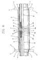
- an apparatus for disposing a tubular covering sleeve 2 for electric-cable joints on a supporting element 3 in accordance with the present invention has been generally identified by reference numeral 1.
- Apparatus 1 comprises a support 4 capable of supporting and locking the sleeve 2 during a step of radial expansion of the latter.
- this support 4 has a pair of plates 5 parallel to each other and mutually spaced apart by substantially the same distance as the length of sleeve 2.
- Each plate is provided with a shaped opening 6 adapted to receive one end 7 of said sleeve 2.
- each of the ends 7 of sleeve 2 has an outer diameter smaller than the outer diameter of an axially intermediate portion 8 thereof, so as to form a shoulder 9 adapted to abut against the edges of a respective opening 6.
- opening 6 of the plates conforms in shape to the respective end 7 of the sleeve and can modify its radial size so as to become wide during expansion of the ends 7 of sleeve 2 and follow deformation of the latter.
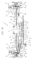
- Apparatus 1 further comprises a pair of expanders 10 each moved by driving means 11 capable of disposing the expanders to a position substantially coaxial with the sleeve 2 put on the support 4 and close to a respective end 7 of the sleeve 2 itself.
- the driving means 11 further carries out introduction of the expanders 10 into the respective ends 7 of sleeve 2, so as to cause radial expansion of the latter.
- the expanders 10 are preferably introduced as far as their distal ends 10a abut against each other at the axially intermediate portion 8 of sleeve 2.
- the two expanders 10 are of the telescopic type and have the same structure.
- the expanders 10 are preferably introduced into sleeve 2 by a synchronised and symmetric movement relative to a symmetry plane "P" transverse to a longitudinal axis "X" of the sleeve 2 and passing through the axially intermediate portion 8 of the latter, so as to cause a radial expansion which too is symmetric relative to said plane "P".
- each of the expanders 10 comprises a radially external tubular body 12 of circular section and provided with a side surface 13 susceptible of engagement with an inner wall 14 of sleeve 2.
- a proximal end 15a of the radially external tubular body 12 is provided with a flange 16 having a tailpiece 17 extending radially away from body 12 and carrying a lead nut 18 installed on a first worm screw 19.
- Distal ends 15b of the radially external tubular bodies 12 face each other and are provided with a bevelled edge in the form of a truncated cone, better seen in Figs. 5-8 , to promote introduction into sleeve 2.
- the first worm screw 19 extends parallel to the longitudinal axis "X" of sleeve 2 and has two portions 19a, 19b with contrary threads, each supporting one of the lead nuts 18 connected to a respective radially external tubular body 12. Said two portions 19a, 19b extend symmetrically starting from the symmetry plane "P" and are supported by a suitable fixed frame, not shown.
- the driving means 11 comprises a first main motor 20, an electric motor for example, operatively in engagement with the first worm screw 19, through either a belt drive 21 for example, or a chain or gear drive.
- a belt 22 is wrapped on a driving pulley 23 integral with the shaft 24 of the first main motor 20 and on a driven pulley 25 integral with the worm screw 10. Rotation of screw 19 in a first direction causes translation of the two radially external tubular bodies 12 close to each other, towards the symmetry plane "P", while rotation in the opposite direction causes mutual spacing apart of same.
- Each expander 10 further comprises a radially internal body 26 movable between a disengaged position ( Figs. 1 and 10 ) at which it lies spaced apart from the respective radially external tubular body 12, preferably at a position axially offset relative to said radially external body 12, and an engaged position ( Fig. 3 ), at which it is inserted in the respective radially external tubular body 12.
- the first main motor 20 connected to the radially external tubular bodies 12 is adapted to simultaneously introduce the expanders 10 into sleeve 2 while the radially internal body 26 is in the engaged position.
- each radially internal body 26 is mounted on a respective main support assembly 27 which in turn is installed on an auxiliary support assembly 28.
- Both the mentioned assemblies 27, 28 are diagrammatically shown in the figures as rectangular tables.
- Each of the main support assemblies 27 and each of the auxiliary support assemblies 28 is moved along a direction parallel to the longitudinal axis "X" of sleeve 2 by a respective second worm screw 29 extending parallel to said longitudinal axis "X" and is supported by a suitable fixed frame, not shown.
- the second worm screw 29 bears a lead nut, not shown, connected to the respective main support assembly 27 through the auxiliary support assembly 28.
- the mentioned lead nut is integral with the auxiliary support assembly 28 and in the accompanying drawings is not shown as it is concealed behind it.
- a second main motor 31 being part of the driving means 11, is operatively engaged with the second worm screw 29 to move the respective radially internal body 26 together with the main 27 and auxiliary 28 support assemblies on parallel guides 30 extending along a direction parallel to the longitudinal axis "X".
- the second main.motor 31 also of the electric type for example, is connected to said second worm screw 29 through either a belt drive 32 for example, or a chain or gear drive.
- a belt 22 is wrapped on a driving pulley 23 integral with the shaft 24 of the second main motor 31 and on a driven pulley 25 integral with the second worm screw 29.
- Rotation of the second screw 29 in a first direction causes translation of the respective radially internal tubular body 26 close to the symmetry plane "P", while rotation in the opposite direction causes moving apart of same.
- the second main motors 31 are operated by a single control unit, not shown, for simultaneous and symmetric movement of the radially internal tubular bodies 26.
- auxiliary support assembly 28 Further mounted on the auxiliary support assembly 28 is a third worm screw 33 extending along a direction transverse to the longitudinal axis "X" of sleeve 2 and to the second worm screw 29 and supporting a concealed lead nut integral with the respective main support assembly 27.
- the auxiliary support assembly 28 therefore is maintained to an interposed position between the second worm screw 29 and the respective main support assembly 27,
- a third main motor 35 is located over the auxiliary support assembly 28 and is connected to the respective t third worm screw 33, to move the main support assembly 27 along mutually parallel guides 34 transverse to the longitudinal axis "X" of sleeve 2 and positioned on the auxiliary support assembly 28.
- the third main motor 35 is connected to the third worm screw 33 by means either of a belt drive 36 for example, or of a chain or gear drive.
- a belt 22 passes over a driving pulley 23 integral with the shaft 24 of the third main motor 35 and over a driven pulley 25 integral with the third worm screw 33.
- Rotation of the third screw 33 in a first direction causes translation of the main support assembly 27 and the respective radially internal tubular body 26 close to the longitudinal axis "X" of sleeve 2, while rotation in the opposite direction causes moving apart of same.
- the radially internal body 26, in a first operating configuration shown in Fig. 2 has a tapered distal end 37, in the form of an ogive for example, to facilitate introduction of the body itself into sleeve 2 and cause gradual expansion of ends 7.
- each of the radially internal bodies 26 comprises a central element 38 which has a distal portion 39 provided with a tapered distal end 39a in the form of an ogive for example, that in the first operating configuration in Figs. 2 , 2a and 10 , constitutes the point of the ogive 37 of the radially internal body 26 considered as a whole.
- the distal portion 39 carrying the ogive comprises a cylindrical length having an annular ridge 42 at the rear, i.e. towards the proximal end 40 of the central element 38.
- the central element 38 further has an intermediate length 43 interposed between the proximal end 40 and the annular ridge 42, which intermediate length 43 is rod-shaped and terminates with an outer thread 44 placed on said proximal end 40.
- the cylindrical length 41 is further provided with radial seats 45 for housing keys 46 set to prevent mutual rotation between the different elements of the radially internal body 46, as better detailed in the following of the present specification.
- the radially internal body 26 further comprises an outer tubular element 47 disposed around the central element 38 and slidably in engagement with said central element 38.
- an intermediate tubular element 48 is located between the central element 38 and the outer tubular element 47 and is slidably in engagement with both of them. While in the embodiment shown only one intermediate element 48 is represented, also adoption of a plurality of intermediate elements 48 coaxial with each other falls within the scope of the present invention, so as to define a multi-stage telescopic radially internal body 26. Preferably, said stages are four in number.
- the outer tubular element 47 has a distal portion 49 provided with a tapered distal end 49a, preferably of frusto-conical shape.
- the distal portion 49 internally has axial splines 50 adapted to slidably house the keys 46 inserted in the radial seats 45 formed in the intermediate tubular element 48, to prevent mutual rotation of said intermediate tubular element 48 relative to the outer tubular element 47.
- the wall of the distal portion 49 of the outer tubular element 47 has an increased thickness than an intermediate length 51 of said outer tubular element 47 and delimits a passageway adapted to receive and guide a distal portion 52 of the intermediate tubular element 48.
- a proximal end 53 of the outer tubular element 47 has an outer thread 54 on which a lead nut 55 is installed, said lead nut 55 being rotatably mounted, by means of bearings 56 for example, in a seat 57 formed in a housing body 58 set up in an integral manner on the main support assembly 27 ( Figs. 2 , 3a and 9 ).
- the lead nut 55 mounted on the outer tubular element 47 is axially locked relative to said housing body 58.
- the distal portion 52 of the intermediate tubular element 48 has a distal end 52a provided with a bevel adapted to give it a frustoconical tapered shape and is internally provided with axial splines 59 into which the keys 46 housed in the radial seats 45 of the cylindrical length 41 of the central element 38 are slidably engaged, to prevent mutual rotation between said intermediate tubular element 48 and the central element 38.
- the distal portion 52 further comprises a cylindrical length 60 having an annular ridge 62 at the rear, i.e. towards a proximal end 61 of the intermediate tubular element 48, which annular ridge 62 is similar to the annular ridge 42 of the central element 38.
- the proximal end 61 of the intermediate tubular element 48 has an outer thread 63 on which a lead nut 64 is mounted which is rotatably engaged, by means of bearings 56 for example, into the proximal end 53 of the outer tubular element 47.
- the lead nut 64 mounted on the intermediate tubular element 48 is axially locked relative to said outer tubular element 47 and is movable therewith.
- a further lead nut 65 is mounted on the thread 44 of the central element 38, is rotatably engaged by means of bearings 56 for example, into the proximal end 61 of the intermediate tubular element 48, and is axially locked relative to said intermediate tubular element 48 and movable therewith.
- the intermediate tubular element 48 is absent and the lead nut 65 of'the central element 38 is directly mounted to the proximal end 53 of the outer tubular element 47.
- the central element 38, intermediate tubular element 48 and outer tubular element 47 are mutually movable between said first operating configuration, at which the ogive-shaped end 39a and the tapered distal ends 49a, 52a form a continuous tapered and preferably substantially conical surface shown in Figs. 2 and 2a , and a second operating configuration at which the point of the ogive-shaped end 39a and the edges 66 of the tapered distal ends 49a, 52a lie in the same plane ( Fig. 9 ).
- the shoulders defined by the annular ridges 42, 62 of the central element 38 and the intermediate tubular element 48 lie against shoulders 67 located on inner surfaces of the intermediate tubular element 48 and the outer tubular element 47, respectively.
- the driving means 11 further comprises a pair of auxiliary motors 68 each of which is fixedly mounted on the main support assembly 27 and is connected to the respective outer tubular element 47 by means of a belt drive 69 for example, or of a chain or gear drive.
- a belt 22 is wrapped on a driving pulley 23 fitted on shaft 24 of the first auxiliary motor 68 and on the lead nut 55 of the outer tubular element 47. Rotation of the lead nut 55 caused by the first auxiliary motor 68 through belt 22 causes translation of the outer tubular element 47 relative to the main support assembly 27 on which it is installed.
- a second pair of auxiliary motors 70 moves the intermediate tubular elements 48.
- each of the second auxiliary motors 70 is installed on the main support assembly 27 and connected to the respective intermediate tubular element 48 by means of either a belt drive 71, or a chain or gear drive.
- a belt 22 is wrapped on a driving pulley 23 fitted on the shaft 24 of the second auxiliary motor 70 and on the lead nut 64 of the intermediate tubular element 48. Rotation of the lead nut 64 caused by the second auxiliary motor 70 through belt 22 causes translation of the intermediate tubular element 48 relative to the outer tubular element 47.
- the second auxiliary motor 70 is moved on guides 72 substantially parallel to the longitudinal axis "X" of sleeve 2 and placed on the first main support assembly 27, to follow the axial movement of the outer tubular element 47.
- Axial-motion transmission from the outer tubular element 47 to the second auxiliary motor 70 preferably takes place through a rigid connection, not shown.
- a third pair of auxiliary motors 73 moves the central elements 38.
- each of the third auxiliary motors 73 is installed on the main support assembly 27 and is connected to the respective central element 38 by means either of a belt drive 74 for example, or of a chain or gear drive.
- a belt 22 is wrapped on a driving pulley 23 fitted on the main shaft 24 of the third auxiliary motor 73 and on the lead nut 65 of the central element 38.
- Rotation of the lead nut 65 caused by the third auxiliary motor 73 through belt 22 causes translation of the central element 38 relative to the intermediate tubular element 48.
- the third auxiliary motor 73 is moved on guides 75 that are substantially parallel to the longitudinal axis "X" of sleeve 2 and placed on the first main support assembly 27, to follow axial motion of the intermediate tubular element 48.
- Axial-motion transmission from the intermediate tubular element 48 to the third auxiliary motor 73 preferably takes place by a rigid connection, not shown.
- Each of the support assemblies 27 comprises a locking device 76 capable of making the radially external tubular body 13 of the expander 10 and the support assembly 27 integral with each other.
- the locking device 76 is defined by a tailpiece 77 of the housing body 58 on which a hydraulic or pneumatic cylinder 78 is mounted ( Fig. 3a ).
- the rod 79 of the cylinder 78 is slidable in a hole 80 formed in the tailpiece 77 along a radial direction.
- the radially external tubular body 12 has a housing 81 located on the proximal end 15a and formed in the flange 16, for example.
- Housing 81 is capable of receiving the rod 79 when the radially internal body 26 is in the above mentioned engaged position, at which it is inserted in the respective radially external tubular body 12.
- the rod 79 is therefore movable between a backward position, at which it is completely contained in hole 80 and an extracted position at which it projects from said hole 80 to enter housing 81.
- the sleeve 2 in a rest configuration i.e. not yet expanded, is positioned on the support 4 and has its ends 7 placed in the openings 6.
- the radially external tubular bodies 12 of the expanders 10 are in alignment with the longitudinal axis "X", their distal ends 15b facing the ends 7 of sleeve 2.
- the radially internal bodies 26 too lie in alignment with the longitudinal axis "X”, their distal ends 37 facing the proximal ends 15a of the radially external tubular bodies 12.
- Each of the radially internal tubular bodies 26 is in the first operating configuration, better shown in Figs. 2 and 2a , in which the ogive-shaped end 39a and the tapered distal ends 49a, 52a form a continuous and substantially conical surface.
- the radially internal bodies 26, together with the respective main 27 and auxiliary 28 support assemblies are moved forward along the respective worm screws 29, until each radially internal body 26 is completely inserted into the corresponding radially external tubular body 12, and housing 81 is disposed close to hole 80 of the tailpiece 77 ( Figs. 3 and 3a ).
- the rod 79 of the cylinder 78 is inserted in hole 81 to lock each radially external tubular body 12 on the respective main support assembly 27.
- the first main motor 20 drives in rotation the first worm screw 19 that, through the lead nuts 18 connected therewith, drags along the two expanders 10, each integral with its main 27 and auxiliary 28 support assemblies, and moves them close to the symmetry plane "P".
- the auxiliary assemblies 28 are preferably disconnected from the second worm screw 29 and move on their guides 30 being dragged along by the first worm screw 19 alone.
- the distal ends 10a of the expanders 10, formed by the distal ends 15b, 37 of the radially external tubular body 12 and the radially internal body 26 enter the ends 7 of sleeve 2 causing radial expansion of said ends until the distal ends 10a, i.e.
- first 68, second 70 and third 73 auxiliary motors move the tubular elements 47, 48 and the central element 38 in a direction opposite to the moving forward direction of the respective radially external tubular body 12, so as to first bring the distal ends 39a of the central elements 38 into mutual contact, then the distal ends 49a, 52a of the tubular elements 47, 48 and finally the distal ends 15b of the radially external tubular bodies 12.
- the main 27 and auxiliary 28 assemblies upon the action of the first main motors 20, go on moving forward towards the symmetry plane "P" taking along with them the radially external tubular body 12, outer tubular element 47 and intermediate tubular element 48 that are integral with each other.
- the third auxiliary motor 73 of each of the two expanders 10 acts on the central element 38 making it move backwards relative to the intermediate tubular element 48, so as to maintain its distal end 39a fixed on the symmetry plane "P".
- the radially external tubular body 12, outer tubular element 47 and intermediate tubular element 48 start gradual expansion also of the axially intermediate portion 8 of sleeve 2.
- the radially internal body 26 is formed with a plurality of telescopic tubular elements disposed around the central element 38. These telescopic tubular elements are moved forward in succession from the innermost one to the outermost once until abutment of the respective tapered distal ends, one after the other.
- the radially internal bodies 26 of the expanders 10 are unlatched and pulled out of the radially external tubular bodies 12.
- the auxiliary assemblies 28 are connected with the respective second worm screws 29 and axially moved apart from sleeve 2 through the action of the second main motors 31.
- the radially internal bodies 26, once separated and axially spaced apart are radially shifted relative to the longitudinal axis "X" of the sleeve 2 itself, moving the main support assemblies 27 along the respective guides 34 upon the action of the third main motors 35 and third worm screws 33 ( Fig. 10 ).
- a method of disposing the tubular covering sleeve 2 for electric-cable joints on the supporting element 3 comprises the steps of causing radial expansion of the tubular sleeve 2 starting from the axially opposite end portions 7 of the sleeve 2 itself and disposing the tubular sleeve 2 in a radially expanded condition on the supporting element 3.
- this radial expansion is preferably carried out gradually starting from the end portions 7 to the axially intermediate portion 8 of the tubular sleeve 2 and simultaneously on both the end portions 7, so that said radial expansion is radially symmetric relative to the above described symmetry plane "P".
- sleeve 2 preferably has an inner diameter larger than the outer diameter of the supporting element 3 on which it is to be disposed and laying is produced by causing a radial shrinkage of sleeve 2 on the supporting element 3 itself.
- the supporting element 3 is preferably an independent tubular support, as specified above in describing operation of apparatus 1.
- the supporting element consists of the ends themselves of the cables to be spliced, the above described operations being conducted directly in the trench.
- the supporting element is made up of the two radially external tubular bodies 12.
- the two radially external tubular bodies 12 are disconnected from the flanges 16 integral with the lead nuts 18 mounted on the first worm screw 19 and need replacement by further bodies 12 expansion of a subsequent sleeve 2 is to be carried out.
- the above described movements are preferably and advantageously controlled and governed by an electronic programmable control unit connected to all or part of motors 20, 31, 35, 68, 70, 73 and possibly to sensors, not shown, adapted to detect the positions, displacements and velocities of the different parts of the apparatus, for example.
Landscapes
- Cable Accessories (AREA)
- Investigating Materials By The Use Of Optical Means Adapted For Particular Applications (AREA)
- Processing Of Terminals (AREA)
- Lining Or Joining Of Plastics Or The Like (AREA)
- Manipulator (AREA)
Claims (27)
- Verfahren zum Anordnen einer röhrenförmigen Abdeckmuffe für Stromkabelverbindungen auf einem tragenden Element, wobei das Verfahren die folgenden Schritte umfasst:Anordnen einer röhrenförmigen Muffe (2) in einer noch nicht aufgeweiteten Ruhekonfiguration;Bewirken radialer Aufweitung der röhrenförmigen Muffe (2), beginnend an axial einander gegenüberliegenden Endabschnitten (7a) der röhrenförmigen Hülse (2);Anordnen der röhrenförmigen Muffe (2) in einem radial aufgeweiteten Zustand auf einem tragenden Element (3);dadurch gekennzeichnet, dass radiale Aufweitung der röhrenförmigen Muffe von der noch nicht aufgeweiteten Ruhekonfiguration ausgehend, mit den Endabschnitten (7a) beginnend, allmählich zu einem axial mittigen Abschnitt (8) der röhrenförmigen Muffe (2) hin ausgeführt wird.
- Verfahren nach Anspruch 1, wobei radiale Aufweitung der röhrenförmigen Muffe gleichzeitig an beiden Endabschnitten (7a) ausgeführt wird.
- Verfahren nach Anspruch 1, wobei die radiale Aufweitung radialsymmetrisch stattfindet.
- Verfahren nach Anspruch 1, wobei die radiale Aufweitung symmetrisch relativ zu einer Symmetrieebene (P) quer zu einer Längsachse (X) der röhrenförmigen Muffe (2) stattfindet, die durch den axial mittigen Abschnitt (8) der röhrenförmigen Muffe (2) hindurch verläuft.
- Verfahren nach Anspruch 1, wobei nach dem Schritt radialer Aufweitung die Muffe (2) einen Innendurchmesser hat, der größer ist als der Außendurchmesser des tragenden Elementes (3).
- Verfahren nach Anspruch 5, wobei nach dem Schritt der radialen Aufweitung die Muffe auf das tragende Element (3) aufgelegt wird und dadurch radiale Schrumpfung der Muffe (2) auf dem tragenden Element (3) bewirkt wird.
- Verfahren nach Anspruch 1, wobei die radiale Aufweitung die Schritte des Anordnens eines Paars von Aufweiteinrichtungen (10) jeweils an einem entsprechenden Ende (7) der röhrenförmigen Muffe (2) und an einer im Wesentlichen koaxialen Position relativ zu der röhrenförmigen Muffe (2) sowie des Einführens der Aufweiteinrichtungen (10) in die jeweiligen Enden (7) der röhrenförmigen Muffe (2) umfasst.
- Verfahren nach Anspruch 7, wobei der Schritt des Einführens der Aufweiteinrichtungen (10) in die jeweiligen Enden (7) der röhrenförmigen Muffe (2) den Schritt des Aneinanderstoßens vorderer Enden (10a) der Aufweiteinrichtungen (10) an dem axial mittigen Abschnitt (8) der Muffe (2) umfasst.
- Verfahren nach Anspruch 8, wobei jede der Aufweiteinrichtungen (10) einen radial außen liegenden röhrenförmigen Körper (12) sowie wenigstens einen radial innen liegenden Körper (26) umfasst, und der Schritt des Aneinanderstoßens der vorderen Enden (10a) der Aufweiteinrichtungen (10) den Schritt umfasst, in dem veranlasst wird, dass wenigstens die radial außen liegenden röhrenförmigen Körper (12) aneinanderstoßen.
- Verfahren nach Anspruch 8, wobei jede der Aufweiteinrichtungen (10) einen radial außen liegenden röhrenförmigen Körper (12) sowie wenigstens einen radial innen liegenden Körper (26) umfasst, und der Schritt, in dem veranlasst wird, dass die vorderen Enden (10a) der Aufweiteinrichtungen (10) aneinanderstoßen, den Schritt, in dem zunächst die radial innen liegenden röhrenförmigen Körper (26) aneinander gestoßen werden, und anschließend den Schritt umfasst, in dem die radial außen liegenden röhrenförmigen Körper (12) aneinander gestoßen werden.
- Verfahren nach Anspruch 9, wobei der Schritt des Anordnens der Muffe (2) in einem elastisch radial aufgeweiteten Zustand auf dem tragenden Element (3) die Schritte des Herausziehens der radial innen liegenden Körper (26), des Einführens des tragenden Elementes (3) in die radial außen liegenden röhrenförmigen Körper (12) und des abschließenden Herausziehens der radial außen liegenden röhrenförmigen Körper (12) aus der Muffe (2) umfasst, um so eine radiale Schrumpfung der Muffe (2) auf dem tragenden Element (3) zu bewirken.
- Verfahren nach Anspruch 9, wobei das tragende Element (3) aus den zwei radial außen liegenden röhrenförmigen Körpern (12) besteht.
- Verfahren nach Anspruch 1, wobei das tragende Element (3) aus einem röhrenförmigen Träger besteht.
- Verfahren nach Anspruch 1, wobei das tragende Element (3) an den Enden zweier zu spleißender Kabel ausgebildet ist.
- Vorrichtung zum Anordnen einer röhrenförmigen Abdeckmuffe für Stromkabelverbindungen auf einem tragenden Element, wobei die Vorrichtung umfasst:einen Träger (4) für eine röhrenförmige Muffe (2);ein Paar Aufweiteinrichtungen (10), die jeweils an einem entsprechenden Ende (7) der Muffe (2) an eine im Wesentlichen koaxiale Position relativ zu der röhrenförmigen Muffe (2) gebracht werden;eine Eindrückeinrichtung (11), die zum Einführen der Aufweiteinrichtungen (10) in die jeweiligen Enden (7) der Muffe (2) sowie zum Bewirken radialer Aufweitung der röhrenförmigen Muffe (2) eingerichtet ist;Einrichtungen zum Anordnen der Muffe (2) in einem radial aufgeweiteten Zustand auf dem tragenden Element (3);dadurch gekennzeichnet, dass der Träger (4) ein Paar Platten (5) umfasst, die parallel zueinander und voneinander im Wesentlichen um den gleichen Abstand wie die Länge der Muffe (2) beabstandet sind, und jeweils mit einer geformten Öffnung (6) versehen sind, die zum Aufnehmen eines Endes (7) der Muffe (2) eingerichtet ist, um die Muffe (2) in einer noch nicht aufgeweiteten Ruhekonfiguration zu tragen.
- Vorrichtung nach Anspruch 15, wobei die Aufweiteinrichtungen (10) strukturell identisch sind.
- Vorrichtung nach Anspruch 15, wobei die Aufweiteinrichtungen (10) teleskopartig sind.
- Vorrichtung nach Anspruch 15, wobei jede der Aufweiteinrichtungen (10) einen radial außen liegenden röhrenförmigen Körper (12), der mit einer Innenwand (14) der Muffe (2) in Eingriff gebracht wird, und einen radial innen liegenden Körper (26) umfasst, der relativ zu dem axial außen liegenden röhrenförmigen Körper (12) axial bewegt werden kann.
- Vorrichtung nach Anspruch 18, wobei der radial innen liegende Körper (26) zwischen einer nicht in Eingriff gebrachten Position, in der er von dem entsprechenden radial außen liegenden Körper (12) beabstandet liegt, und einer in Eingriff gebrachten Position bewegt werden kann, in der er in den entsprechenden radial außen liegenden röhrenförmigen Körper (12) eingeführt ist.
- Vorrichtung nach Anspruch 18, wobei der radial innen liegende Körper (26) ein spitzbogenförmiges vorderes Ende hat.
- Vorrichtung nach Anspruch 19, wobei die Eindrückeinrichtung (11) einen ersten Hauptmotor (20) umfasst, der mit den radial außen liegenden röhrenförmigen Körpern (12) verbunden und so eingerichtet ist, dass er die Aufweiteinrichtungen (10) gleichzeitig in die Muffe (2) einführt, während sich der radial innen liegende Körper (26) in der in Eingriff gebrachten Position befindet.
- Vorrichtung nach Anspruch 21, wobei die Eindrückeinrichtung (11) des Weiteren einen zweiten Hauptmotor (31) für jeden der radial innen liegenden Körper (26) umfasst, der den entsprechenden radial innen liegenden röhrenförmigen Körper (26) in einer Richtung parallel zu der Längsachse (X) der Muffe (2) verschiebt.
- Vorrichtung nach Anspruch 18, wobei der radial innen liegende Körper (26) ein mittiges Element (38), das ein spitzbogenförmiges vorderes Ende (39a) hat, und ein äußeres röhrenförmiges Element (47) umfasst, das um das mittige Element (38) herum angeordnet ist und ein sich verjüngendes vorderes Ende (49a) hat, das axial relativ zu dem mittigen Element (38) bewegt werden kann.
- Vorrichtung nach Anspruch 23, wobei der radial innen liegende Körper (26) des Weiteren wenigstens ein röhrenförmiges Zwischenelement (48) umfasst, das sich zwischen dem mittigen Element (38) und dem äußeren röhrenförmigen Element (47) befindet und das ein sich ein verjüngendes vorderes Ende (52a) hat, das axial relativ zu dem mittigen Element (38) und dem äußeren röhrenförmigen Element (47) bewegt werden kann.
- Vorrichtung nach Anspruch 24, wobei das mittige Element (38), das wenigstens eine röhrenförmige Zwischenelement (48) und das äußere röhrenförmige Element (47) zwischen einer ersten Funktionskonfiguration, in der das spitzbogenförmige Ende (39a) und die sich verjüngenden vorderen Enden (49a, 52a) eine im Wesentlichen durchgehende konische Fläche bilden, und einer zweiten Funktionskonfiguration zueinander bewegt werden können, in der die Spitze des spitzbogenförmigen Endes (39a) und die Ränder (66) der sich verjüngenden vorderen Enden (49a, 52a) in der gleichen Ebene liegen.
- Vorrichtung nach Anspruch 24, wobei Keilprofile (46) zwischen dem mittigen Element (38) und den röhrenförmigen Elementen (47, 48) angeordnet sind, um Drehung derselben zueinander zu verhindern.
- Vorrichtung nach Anspruch 24, wobei die Eindrückeinrichtung (11) wenigstens ein Paar erster Hilfsmotoren (68), die jeweils mit einem äußeren röhrenförmigen Element (47) des entsprechenden radial innen liegenden Körpers (26) verbunden sind, wenigstens ein Paar zweiter Hilfsmotoren (70), die jeweils mit einem röhrenförmigen Zwischenelement (47) verbunden sind, sowie ein Paar dritter Hilfsmotoren (73) umfasst, die jeweils mit einem mittigen Element (38) des entsprechenden radial innen liegenden Körpers (26) verbunden sind, um die röhrenförmigen Elemente (47, 48) und das mittige Element (38) in einer Richtung entgegengesetzt zu der Vorwärtsbewegungsrichtung des entsprechenden radial außen liegenden röhrenförmigen Körpers (12) in der Muffe zu bewegen, um so zunächst die vorderen Enden (39a) der mittigen Elemente (38) miteinander in Kontakt zu bringen, dann die vorderen Enden (49a, 52a) der röhrenförmigen Elemente (47, 48) in Kontakt miteinander zu bringen und schließlich die vorderen Enden (15b) der radial außen liegenden röhrenförmigen Körper (12) in Kontakt miteinander zu bringen.
Priority Applications (1)
| Application Number | Priority Date | Filing Date | Title |
|---|---|---|---|
| EP12169039.0A EP2506373A3 (de) | 2005-12-28 | 2005-12-28 | Vorrichtung zum Aufschieben einer rohrförmigen Hülse auf ein Stützelement |
Applications Claiming Priority (1)
| Application Number | Priority Date | Filing Date | Title |
|---|---|---|---|
| PCT/IT2005/000768 WO2007074481A1 (en) | 2005-12-28 | 2005-12-28 | Method of disposing a tubular sleeve on a supporting element and apparatus to put said method into practice |
Related Child Applications (2)
| Application Number | Title | Priority Date | Filing Date |
|---|---|---|---|
| EP12169039.0A Division-Into EP2506373A3 (de) | 2005-12-28 | 2005-12-28 | Vorrichtung zum Aufschieben einer rohrförmigen Hülse auf ein Stützelement |
| EP12169039.0A Division EP2506373A3 (de) | 2005-12-28 | 2005-12-28 | Vorrichtung zum Aufschieben einer rohrförmigen Hülse auf ein Stützelement |
Publications (2)
| Publication Number | Publication Date |
|---|---|
| EP1966861A1 EP1966861A1 (de) | 2008-09-10 |
| EP1966861B1 true EP1966861B1 (de) | 2014-05-14 |
Family
ID=37067480
Family Applications (2)
| Application Number | Title | Priority Date | Filing Date |
|---|---|---|---|
| EP12169039.0A Withdrawn EP2506373A3 (de) | 2005-12-28 | 2005-12-28 | Vorrichtung zum Aufschieben einer rohrförmigen Hülse auf ein Stützelement |
| EP05850985.2A Expired - Lifetime EP1966861B1 (de) | 2005-12-28 | 2005-12-28 | Verfahren zum aufbringen einer kabelmuffe auf einen stützelement und vorrichtung zur durchführung des verfahrens |
Family Applications Before (1)
| Application Number | Title | Priority Date | Filing Date |
|---|---|---|---|
| EP12169039.0A Withdrawn EP2506373A3 (de) | 2005-12-28 | 2005-12-28 | Vorrichtung zum Aufschieben einer rohrförmigen Hülse auf ein Stützelement |
Country Status (9)
| Country | Link |
|---|---|
| US (2) | US8273200B2 (de) |
| EP (2) | EP2506373A3 (de) |
| CN (1) | CN101346860B (de) |
| AU (1) | AU2005339513B2 (de) |
| BR (1) | BRPI0520810A2 (de) |
| CA (1) | CA2633302C (de) |
| ES (1) | ES2490792T3 (de) |
| NZ (1) | NZ568559A (de) |
| WO (1) | WO2007074481A1 (de) |
Families Citing this family (11)
| Publication number | Priority date | Publication date | Assignee | Title |
|---|---|---|---|---|
| ES2379356T3 (es) * | 2004-10-27 | 2012-04-25 | Prysmian S.P.A. | Procedimiento y dispositivo para el revestimiento del área de conexión entre al menos dos elementos alargados, en particular entre cables eléctricos |
| WO2007046115A1 (en) * | 2005-10-19 | 2007-04-26 | Prysmian Cavi E Sistemi Energia S.R.L. | Method and apparatus for joining a pair of electric cables |
| US8853563B2 (en) | 2010-04-16 | 2014-10-07 | Thomas & Betts International, Llc | Cold shrink assembly |
| US9202612B2 (en) | 2012-09-28 | 2015-12-01 | Thomas & Betts International, Llc | Cold shrink assembly |
| CN107408798B (zh) * | 2015-05-26 | 2019-05-28 | 三菱电机株式会社 | 电气设备以及电气设备的制造方法 |
| TWI711238B (zh) * | 2019-07-26 | 2020-11-21 | 日商永木精機股份有限公司 | 套筒裝設工具及套筒裝設方法 |
| CN110890723B (zh) * | 2019-12-20 | 2025-07-29 | 江苏远航电缆附件有限公司 | 一种电缆附件中间接头扩张装置 |
| US11888278B2 (en) | 2021-03-24 | 2024-01-30 | Richards Mfg. Co. | Cold shrink core |
| CN113771372B (zh) * | 2021-07-22 | 2024-05-28 | 江苏恒源园艺用品有限公司 | 一种金属管用自动热缩套帽机及金属管套帽工艺 |
| CN118418467B (zh) * | 2024-07-02 | 2024-09-20 | 福建正阳汽车部件有限公司 | 一种电池钢带抱箍自动定位套热收缩管机 |
| CN120228928B (zh) * | 2025-05-12 | 2025-09-23 | 江苏齐杰机械有限公司 | 一种套筒自动装配设备 |
Family Cites Families (12)
| Publication number | Priority date | Publication date | Assignee | Title |
|---|---|---|---|---|
| US3495301A (en) * | 1967-06-23 | 1970-02-17 | Phillips Petroleum Co | Tube expanding apparatus |
| CN85204897U (zh) * | 1985-11-16 | 1987-03-11 | 吕永起 | 电缆接头塑料护套 |
| IT1229810B (it) * | 1988-11-11 | 1991-09-13 | Pirelli Cavi Spa | Procedimento ed apparecchiatura per inserire un supporto rigido in un manicotto per giunti di cavi elettrici. |
| SE503278C2 (sv) * | 1993-06-07 | 1996-05-13 | Kabeldon Ab | Förfarande vid skarvning av två kabelparter, samt skarvkropp och monteringsverktyg för användning vid förfarandet |
| US5467515A (en) * | 1994-09-28 | 1995-11-21 | Amerace Corporation | Alternative cold shrink device |
| DE19510598A1 (de) | 1995-03-23 | 1996-09-26 | Zittauer Kunststoff Gmbh | Aufschiebehilfe für das Aufschieben und Positionieren von hülsenförmigen, elastischen Bauteilen auf zylindrische oder konische Grundkörper |
| FR2742597B1 (fr) * | 1995-12-19 | 1998-01-23 | Silec Liaisons Elec | Dispositif d'expansion radiale d'un manchon elastomere |
| US6245999B1 (en) * | 1996-12-19 | 2001-06-12 | Raychem Limited | Cable enclosure arrangement |
| FR2761830B1 (fr) * | 1997-04-07 | 2000-01-28 | Pirelli Cables Sa | Support de jonction a extraction autonome commandee |
| FR2786954B1 (fr) * | 1998-12-02 | 2001-01-12 | Sagem | Dispositif de maintien en expansion d'un manchon elastique, et procede et dispositif de mise en expansion d'un manchon elastique |
| GB0017340D0 (en) | 2000-07-15 | 2000-08-30 | Tyco Electronics Raychem Gmbh | Multiple expander |
| AU2001269335A1 (en) | 2000-07-15 | 2002-01-30 | Tyco Electronics Raychem Gmbh | Multiple expander |
-
2005
- 2005-12-28 EP EP12169039.0A patent/EP2506373A3/de not_active Withdrawn
- 2005-12-28 ES ES05850985.2T patent/ES2490792T3/es not_active Expired - Lifetime
- 2005-12-28 AU AU2005339513A patent/AU2005339513B2/en not_active Ceased
- 2005-12-28 EP EP05850985.2A patent/EP1966861B1/de not_active Expired - Lifetime
- 2005-12-28 BR BRPI0520810-6A patent/BRPI0520810A2/pt not_active IP Right Cessation
- 2005-12-28 NZ NZ568559A patent/NZ568559A/en not_active IP Right Cessation
- 2005-12-28 CN CN2005800524167A patent/CN101346860B/zh not_active Expired - Fee Related
- 2005-12-28 WO PCT/IT2005/000768 patent/WO2007074481A1/en not_active Ceased
- 2005-12-28 US US12/087,123 patent/US8273200B2/en not_active Expired - Fee Related
- 2005-12-28 CA CA2633302A patent/CA2633302C/en not_active Expired - Fee Related
-
2012
- 2012-07-26 US US13/559,040 patent/US8789570B2/en not_active Expired - Fee Related
Also Published As
| Publication number | Publication date |
|---|---|
| US20090065125A1 (en) | 2009-03-12 |
| CN101346860A (zh) | 2009-01-14 |
| ES2490792T3 (es) | 2014-09-04 |
| BRPI0520810A2 (pt) | 2010-03-16 |
| CA2633302C (en) | 2014-02-11 |
| WO2007074481A1 (en) | 2007-07-05 |
| CA2633302A1 (en) | 2007-07-05 |
| AU2005339513A1 (en) | 2007-07-05 |
| CN101346860B (zh) | 2011-08-31 |
| EP2506373A3 (de) | 2015-11-11 |
| US20130061465A1 (en) | 2013-03-14 |
| US8273200B2 (en) | 2012-09-25 |
| EP2506373A2 (de) | 2012-10-03 |
| EP1966861A1 (de) | 2008-09-10 |
| US8789570B2 (en) | 2014-07-29 |
| AU2005339513B2 (en) | 2011-03-17 |
| NZ568559A (en) | 2011-03-31 |
Similar Documents
| Publication | Publication Date | Title |
|---|---|---|
| US8789570B2 (en) | Apparatuses for disposing tubular covering sleeves for electric-cable joints on supporting elements | |
| US9613735B2 (en) | Apparatuses for joining pairs of electric cables | |
| AU668521B2 (en) | Enclosure assembly for use over elongate cylindrical objects such as electric cable splices | |
| US5486388A (en) | Enclosure assembly for elongate cylindrical objects such as electric cable splices | |
| EP1759443B1 (de) | Verfahren zum umhüllen eines langgestreckten gegenstands und vorrichtung zum umhüllen dieses langgestreckten gegenstands | |
| EP1966863B1 (de) | Verfahren zum verbinden und dazugehörige verbindung für elektrische kabel | |
| EP2656463B1 (de) | Verfahren zum herstellen einer verbindungsvorrichtung für mittel- und hochspannungskabel | |
| EP2328248A2 (de) | Stützrohr für Kaltschrumpffolien für Stromkabelverbindungen | |
| EP2186177B1 (de) | Vorrichtung zur ausdehnung eines rohrförmigen elastischen körpers | |
| WO2012161589A1 (en) | Method for establishing a cold shrink joint and a shrink sleeve support tube system |
Legal Events
| Date | Code | Title | Description |
|---|---|---|---|
| PUAI | Public reference made under article 153(3) epc to a published international application that has entered the european phase |
Free format text: ORIGINAL CODE: 0009012 |
|
| 17P | Request for examination filed |
Effective date: 20080606 |
|
| AK | Designated contracting states |
Kind code of ref document: A1 Designated state(s): AT BE BG CH CY CZ DE DK EE ES FI FR GB GR HU IE IS IT LI LT LU LV MC NL PL PT RO SE SI SK TR |
|
| RAP1 | Party data changed (applicant data changed or rights of an application transferred) |
Owner name: PRYSMIAN S.P.A. |
|
| 17Q | First examination report despatched |
Effective date: 20100527 |
|
| DAX | Request for extension of the european patent (deleted) | ||
| GRAP | Despatch of communication of intention to grant a patent |
Free format text: ORIGINAL CODE: EPIDOSNIGR1 |
|
| INTG | Intention to grant announced |
Effective date: 20140121 |
|
| GRAS | Grant fee paid |
Free format text: ORIGINAL CODE: EPIDOSNIGR3 |
|
| GRAA | (expected) grant |
Free format text: ORIGINAL CODE: 0009210 |
|
| AK | Designated contracting states |
Kind code of ref document: B1 Designated state(s): AT BE BG CH CY CZ DE DK EE ES FI FR GB GR HU IE IS IT LI LT LU LV MC NL PL PT RO SE SI SK TR |
|
| REG | Reference to a national code |
Ref country code: GB Ref legal event code: FG4D |
|
| REG | Reference to a national code |
Ref country code: AT Ref legal event code: REF Ref document number: 668916 Country of ref document: AT Kind code of ref document: T Effective date: 20140615 |
|
| REG | Reference to a national code |
Ref country code: IE Ref legal event code: FG4D |
|
| REG | Reference to a national code |
Ref country code: DE Ref legal event code: R096 Ref document number: 602005043666 Country of ref document: DE Effective date: 20140626 |
|
| REG | Reference to a national code |
Ref country code: ES Ref legal event code: FG2A Ref document number: 2490792 Country of ref document: ES Kind code of ref document: T3 Effective date: 20140904 |
|
| REG | Reference to a national code |
Ref country code: NL Ref legal event code: VDEP Effective date: 20140514 Ref country code: AT Ref legal event code: MK05 Ref document number: 668916 Country of ref document: AT Kind code of ref document: T Effective date: 20140514 |
|
| REG | Reference to a national code |
Ref country code: LT Ref legal event code: MG4D |
|
| PG25 | Lapsed in a contracting state [announced via postgrant information from national office to epo] |
Ref country code: GR Free format text: LAPSE BECAUSE OF FAILURE TO SUBMIT A TRANSLATION OF THE DESCRIPTION OR TO PAY THE FEE WITHIN THE PRESCRIBED TIME-LIMIT Effective date: 20140815 Ref country code: FI Free format text: LAPSE BECAUSE OF FAILURE TO SUBMIT A TRANSLATION OF THE DESCRIPTION OR TO PAY THE FEE WITHIN THE PRESCRIBED TIME-LIMIT Effective date: 20140514 Ref country code: LT Free format text: LAPSE BECAUSE OF FAILURE TO SUBMIT A TRANSLATION OF THE DESCRIPTION OR TO PAY THE FEE WITHIN THE PRESCRIBED TIME-LIMIT Effective date: 20140514 Ref country code: CY Free format text: LAPSE BECAUSE OF FAILURE TO SUBMIT A TRANSLATION OF THE DESCRIPTION OR TO PAY THE FEE WITHIN THE PRESCRIBED TIME-LIMIT Effective date: 20140514 Ref country code: IS Free format text: LAPSE BECAUSE OF FAILURE TO SUBMIT A TRANSLATION OF THE DESCRIPTION OR TO PAY THE FEE WITHIN THE PRESCRIBED TIME-LIMIT Effective date: 20140914 |
|
| PG25 | Lapsed in a contracting state [announced via postgrant information from national office to epo] |
Ref country code: AT Free format text: LAPSE BECAUSE OF FAILURE TO SUBMIT A TRANSLATION OF THE DESCRIPTION OR TO PAY THE FEE WITHIN THE PRESCRIBED TIME-LIMIT Effective date: 20140514 Ref country code: LV Free format text: LAPSE BECAUSE OF FAILURE TO SUBMIT A TRANSLATION OF THE DESCRIPTION OR TO PAY THE FEE WITHIN THE PRESCRIBED TIME-LIMIT Effective date: 20140514 Ref country code: PL Free format text: LAPSE BECAUSE OF FAILURE TO SUBMIT A TRANSLATION OF THE DESCRIPTION OR TO PAY THE FEE WITHIN THE PRESCRIBED TIME-LIMIT Effective date: 20140514 Ref country code: SE Free format text: LAPSE BECAUSE OF FAILURE TO SUBMIT A TRANSLATION OF THE DESCRIPTION OR TO PAY THE FEE WITHIN THE PRESCRIBED TIME-LIMIT Effective date: 20140514 |
|
| PG25 | Lapsed in a contracting state [announced via postgrant information from national office to epo] |
Ref country code: PT Free format text: LAPSE BECAUSE OF FAILURE TO SUBMIT A TRANSLATION OF THE DESCRIPTION OR TO PAY THE FEE WITHIN THE PRESCRIBED TIME-LIMIT Effective date: 20140915 |
|
| PG25 | Lapsed in a contracting state [announced via postgrant information from national office to epo] |
Ref country code: BE Free format text: LAPSE BECAUSE OF FAILURE TO SUBMIT A TRANSLATION OF THE DESCRIPTION OR TO PAY THE FEE WITHIN THE PRESCRIBED TIME-LIMIT Effective date: 20140514 Ref country code: DK Free format text: LAPSE BECAUSE OF FAILURE TO SUBMIT A TRANSLATION OF THE DESCRIPTION OR TO PAY THE FEE WITHIN THE PRESCRIBED TIME-LIMIT Effective date: 20140514 Ref country code: EE Free format text: LAPSE BECAUSE OF FAILURE TO SUBMIT A TRANSLATION OF THE DESCRIPTION OR TO PAY THE FEE WITHIN THE PRESCRIBED TIME-LIMIT Effective date: 20140514 Ref country code: RO Free format text: LAPSE BECAUSE OF FAILURE TO SUBMIT A TRANSLATION OF THE DESCRIPTION OR TO PAY THE FEE WITHIN THE PRESCRIBED TIME-LIMIT Effective date: 20140514 Ref country code: CZ Free format text: LAPSE BECAUSE OF FAILURE TO SUBMIT A TRANSLATION OF THE DESCRIPTION OR TO PAY THE FEE WITHIN THE PRESCRIBED TIME-LIMIT Effective date: 20140514 Ref country code: SK Free format text: LAPSE BECAUSE OF FAILURE TO SUBMIT A TRANSLATION OF THE DESCRIPTION OR TO PAY THE FEE WITHIN THE PRESCRIBED TIME-LIMIT Effective date: 20140514 |
|
| REG | Reference to a national code |
Ref country code: DE Ref legal event code: R097 Ref document number: 602005043666 Country of ref document: DE |
|
| PG25 | Lapsed in a contracting state [announced via postgrant information from national office to epo] |
Ref country code: NL Free format text: LAPSE BECAUSE OF FAILURE TO SUBMIT A TRANSLATION OF THE DESCRIPTION OR TO PAY THE FEE WITHIN THE PRESCRIBED TIME-LIMIT Effective date: 20140514 |
|
| PLBE | No opposition filed within time limit |
Free format text: ORIGINAL CODE: 0009261 |
|
| STAA | Information on the status of an ep patent application or granted ep patent |
Free format text: STATUS: NO OPPOSITION FILED WITHIN TIME LIMIT |
|
| 26N | No opposition filed |
Effective date: 20150217 |
|
| REG | Reference to a national code |
Ref country code: DE Ref legal event code: R097 Ref document number: 602005043666 Country of ref document: DE Effective date: 20150217 |
|
| PG25 | Lapsed in a contracting state [announced via postgrant information from national office to epo] |
Ref country code: SI Free format text: LAPSE BECAUSE OF FAILURE TO SUBMIT A TRANSLATION OF THE DESCRIPTION OR TO PAY THE FEE WITHIN THE PRESCRIBED TIME-LIMIT Effective date: 20140514 Ref country code: LU Free format text: LAPSE BECAUSE OF FAILURE TO SUBMIT A TRANSLATION OF THE DESCRIPTION OR TO PAY THE FEE WITHIN THE PRESCRIBED TIME-LIMIT Effective date: 20141228 |
|
| REG | Reference to a national code |
Ref country code: CH Ref legal event code: PL |
|
| REG | Reference to a national code |
Ref country code: IE Ref legal event code: MM4A |
|
| PG25 | Lapsed in a contracting state [announced via postgrant information from national office to epo] |
Ref country code: IE Free format text: LAPSE BECAUSE OF NON-PAYMENT OF DUE FEES Effective date: 20141228 Ref country code: LI Free format text: LAPSE BECAUSE OF NON-PAYMENT OF DUE FEES Effective date: 20141231 Ref country code: CH Free format text: LAPSE BECAUSE OF NON-PAYMENT OF DUE FEES Effective date: 20141231 |
|
| REG | Reference to a national code |
Ref country code: FR Ref legal event code: PLFP Year of fee payment: 11 |
|
| PG25 | Lapsed in a contracting state [announced via postgrant information from national office to epo] |
Ref country code: MC Free format text: LAPSE BECAUSE OF FAILURE TO SUBMIT A TRANSLATION OF THE DESCRIPTION OR TO PAY THE FEE WITHIN THE PRESCRIBED TIME-LIMIT Effective date: 20140514 Ref country code: BG Free format text: LAPSE BECAUSE OF FAILURE TO SUBMIT A TRANSLATION OF THE DESCRIPTION OR TO PAY THE FEE WITHIN THE PRESCRIBED TIME-LIMIT Effective date: 20140514 |
|
| PG25 | Lapsed in a contracting state [announced via postgrant information from national office to epo] |
Ref country code: TR Free format text: LAPSE BECAUSE OF FAILURE TO SUBMIT A TRANSLATION OF THE DESCRIPTION OR TO PAY THE FEE WITHIN THE PRESCRIBED TIME-LIMIT Effective date: 20140514 Ref country code: HU Free format text: LAPSE BECAUSE OF FAILURE TO SUBMIT A TRANSLATION OF THE DESCRIPTION OR TO PAY THE FEE WITHIN THE PRESCRIBED TIME-LIMIT; INVALID AB INITIO Effective date: 20051228 |
|
| REG | Reference to a national code |
Ref country code: FR Ref legal event code: PLFP Year of fee payment: 12 |
|
| PG25 | Lapsed in a contracting state [announced via postgrant information from national office to epo] |
Ref country code: IT Free format text: LAPSE BECAUSE OF NON-PAYMENT OF DUE FEES Effective date: 20151228 |
|
| PG25 | Lapsed in a contracting state [announced via postgrant information from national office to epo] |
Ref country code: IT Free format text: LAPSE BECAUSE OF NON-PAYMENT OF DUE FEES Effective date: 20151228 |
|
| PGRI | Patent reinstated in contracting state [announced from national office to epo] |
Ref country code: IT Effective date: 20170710 |
|
| REG | Reference to a national code |
Ref country code: FR Ref legal event code: PLFP Year of fee payment: 13 |
|
| PGFP | Annual fee paid to national office [announced via postgrant information from national office to epo] |
Ref country code: GB Payment date: 20201228 Year of fee payment: 16 Ref country code: FR Payment date: 20201227 Year of fee payment: 16 |
|
| PGFP | Annual fee paid to national office [announced via postgrant information from national office to epo] |
Ref country code: IT Payment date: 20201221 Year of fee payment: 16 |
|
| PGFP | Annual fee paid to national office [announced via postgrant information from national office to epo] |
Ref country code: DE Payment date: 20201229 Year of fee payment: 16 Ref country code: ES Payment date: 20210104 Year of fee payment: 16 |
|
| REG | Reference to a national code |
Ref country code: DE Ref legal event code: R119 Ref document number: 602005043666 Country of ref document: DE |
|
| GBPC | Gb: european patent ceased through non-payment of renewal fee |
Effective date: 20211228 |
|
| PG25 | Lapsed in a contracting state [announced via postgrant information from national office to epo] |
Ref country code: GB Free format text: LAPSE BECAUSE OF NON-PAYMENT OF DUE FEES Effective date: 20211228 Ref country code: DE Free format text: LAPSE BECAUSE OF NON-PAYMENT OF DUE FEES Effective date: 20220701 |
|
| PG25 | Lapsed in a contracting state [announced via postgrant information from national office to epo] |
Ref country code: FR Free format text: LAPSE BECAUSE OF NON-PAYMENT OF DUE FEES Effective date: 20211231 |
|
| REG | Reference to a national code |
Ref country code: ES Ref legal event code: FD2A Effective date: 20230223 |
|
| PG25 | Lapsed in a contracting state [announced via postgrant information from national office to epo] |
Ref country code: ES Free format text: LAPSE BECAUSE OF NON-PAYMENT OF DUE FEES Effective date: 20211229 |
|
| PG25 | Lapsed in a contracting state [announced via postgrant information from national office to epo] |
Ref country code: IT Free format text: LAPSE BECAUSE OF NON-PAYMENT OF DUE FEES Effective date: 20211231 |