EP1967084A1 - Garment - Google Patents
Garment Download PDFInfo
- Publication number
- EP1967084A1 EP1967084A1 EP06821858A EP06821858A EP1967084A1 EP 1967084 A1 EP1967084 A1 EP 1967084A1 EP 06821858 A EP06821858 A EP 06821858A EP 06821858 A EP06821858 A EP 06821858A EP 1967084 A1 EP1967084 A1 EP 1967084A1
- Authority
- EP
- European Patent Office
- Prior art keywords
- tightening
- tightening portion
- strong
- weak
- yarn
- Prior art date
- Legal status (The legal status is an assumption and is not a legal conclusion. Google has not performed a legal analysis and makes no representation as to the accuracy of the status listed.)
- Withdrawn
Links
- 238000003780 insertion Methods 0.000 claims abstract description 38
- 230000037431 insertion Effects 0.000 claims abstract description 38
- 230000003014 reinforcing effect Effects 0.000 claims abstract description 27
- 239000004744 fabric Substances 0.000 claims description 122
- 230000037237 body shape Effects 0.000 abstract description 7
- 238000013461 design Methods 0.000 abstract description 2
- 238000010586 diagram Methods 0.000 description 17
- 238000009940 knitting Methods 0.000 description 15
- 210000000689 upper leg Anatomy 0.000 description 15
- 239000000945 filler Substances 0.000 description 7
- 230000002093 peripheral effect Effects 0.000 description 6
- 230000003187 abdominal effect Effects 0.000 description 5
- 238000012986 modification Methods 0.000 description 5
- 230000004048 modification Effects 0.000 description 5
- 239000004677 Nylon Substances 0.000 description 4
- 230000000694 effects Effects 0.000 description 4
- 229920001778 nylon Polymers 0.000 description 4
- 229920002635 polyurethane Polymers 0.000 description 4
- 239000004814 polyurethane Substances 0.000 description 4
- 210000001015 abdomen Anatomy 0.000 description 3
- 239000012141 concentrate Substances 0.000 description 2
- 238000004043 dyeing Methods 0.000 description 2
- 210000003314 quadriceps muscle Anatomy 0.000 description 2
- 230000003466 anti-cipated effect Effects 0.000 description 1
- 238000013459 approach Methods 0.000 description 1
- 230000007423 decrease Effects 0.000 description 1
- 210000004013 groin Anatomy 0.000 description 1
- 210000002414 leg Anatomy 0.000 description 1
- 238000005259 measurement Methods 0.000 description 1
Images







Classifications
-
- D—TEXTILES; PAPER
- D04—BRAIDING; LACE-MAKING; KNITTING; TRIMMINGS; NON-WOVEN FABRICS
- D04B—KNITTING
- D04B21/00—Warp knitting processes for the production of fabrics or articles not dependent on the use of particular machines; Fabrics or articles defined by such processes
- D04B21/20—Warp knitting processes for the production of fabrics or articles not dependent on the use of particular machines; Fabrics or articles defined by such processes specially adapted for knitting articles of particular configuration
- D04B21/207—Wearing apparel or garment blanks
-
- A—HUMAN NECESSITIES
- A41—WEARING APPAREL
- A41C—CORSETS; BRASSIERES
- A41C1/00—Corsets or girdles
- A41C1/003—Panty-girdles
-
- A—HUMAN NECESSITIES
- A41—WEARING APPAREL
- A41C—CORSETS; BRASSIERES
- A41C1/00—Corsets or girdles
- A41C1/02—Elastic corsets
-
- A—HUMAN NECESSITIES
- A41—WEARING APPAREL
- A41B—SHIRTS; UNDERWEAR; BABY LINEN; HANDKERCHIEFS
- A41B11/00—Hosiery; Panti-hose
- A41B11/003—Hosiery with intermediate sections of different elasticity
-
- D—TEXTILES; PAPER
- D10—INDEXING SCHEME ASSOCIATED WITH SUBLASSES OF SECTION D, RELATING TO TEXTILES
- D10B—INDEXING SCHEME ASSOCIATED WITH SUBLASSES OF SECTION D, RELATING TO TEXTILES
- D10B2501/00—Wearing apparel
- D10B2501/02—Underwear
Definitions
- the present invention relates to a garment, and particularly to a garment worn attached to a body.
- a girdle, a body suit, a brassiere, a swim suit, shorts, and other conventional garments that are worn attached tightly to a body have a tightening portion formed on a predetermined section of such garments in order to manipulate the body shape of a wearer, correct the wearer's posture, and improve the wearer's motor ability by means of the tightening force of the tightening portion.
- a tightening portion formed on a predetermined section of such garments in order to manipulate the body shape of a wearer, correct the wearer's posture, and improve the wearer's motor ability by means of the tightening force of the tightening portion.
- a filler cloth is applied to a part of the garment to provide a strong tightening force, or the thickness of an elastic yarn to be knitted is made thicker.
- application of a filler cloth is not preferred, since the thickness of the fabric of the tightening portion increases by the thickness of the filler cloth.
- the border between the parts with different tightening forces extends only in a direction in which the elastic yarn is knitted, and thus a desired shape of tightening portion cannot be obtained.
- Patent Document 1 Japanese Patent Registered No. 3461316
- the present invention has been contrived to solve the aforementioned problems, and its object is to provide a garment that is capable of obtaining a desired shape of tightening portion without using a filler cloth, and obtaining a sufficient difference in tightening force between sections to be and not to be provided with a strong tightening force, and that has a small limitation in adopting a ground structure serving as a base of a knitted fabric.
- the garment of the present invention is a garment attached tightly to a body, comprising a belt-like tightening portion that has a strong tightening portion, which is a part having a relatively strong tightening force, and a weak tightening portion, which is a part having a relatively weak tightening force, where the strong tightening portion and the weak tightening portion are switched in a belt-like longitudinal direction, wherein, in the tightening portion, a yarn for reinforcing the tightening force is continuously knitted into a ground structure throughout the strong tightening portion and the weak tightening portion, and a knit structure of the yarn for reinforcing the tightening force has a greater number of looping structures in the strong tightening portion than the weak tightening portion, and has a greater number of insertion structures in the weak tightening portion than the strong tightening portion.
- the yarn for reinforcing the tightening force is continuously knitted into the ground structure in the belt-like tightening portion, so that the strong tightening portion is formed mainly by the looping structures and the weak tightening portion is formed mainly by the insertion structures. Therefore, the strong tightening portion is formed into a desired shape at an appropriate position of the knitted fabric, and a sufficient difference in the tightening force between the strong tightening portion and the other portion and also between the strong tightening portion and the weak tightening portion can be obtained.
- the garment of the present invention is a garment attached tightly to a body, comprising a belt-like tightening portion, wherein the tightening portion and at least a part of a fabric main body portion that is adjacent to the tightening portion comprise a common ground structure, the tightening portion has a strong tightening portion, which is a part having a relatively strong tightening force, and a weak tightening portion, which is a part having a relatively weak tightening force, where the strong tightening portion and the weak tightening portion are switched in a belt-like longitudinal direction, in the tightening portion, a yarn for reinforcing the tightening force is continuously knitted into a ground structures throughout the strong tightening portion and the weak tightening portion, and a knit structure of the yarn for reinforcing the tightening forces has a greater number of looping structures in the strong tightening portion than the weak tightening portion, and has a greater number of insertion structures in the weak tightening portion than the strong tightening portion
- the yarn for reinforcing the tightening force is continuously knitted into the ground structure in the belt-like tightening portion, so that the strong tightening portion is formed mainly by the looping structures and the weak tightening portion is formed mainly by the insertion structures. Therefore, the strong tightening portion is formed into a desired shape at an appropriate position of the knitted fabric, a sufficient difference in the tightening force between the strong tightening portion and the other portion and also between the strong tightening portion and the weak tightening portion can be obtained, and the ground structure can be obtained as a structure that is common between the tightening portion and the fabric main body portion which is adjacent to the tightening portion.
- the garment of the present invention is a garment attached tightly to a body, comprising a belt-like tightening portion, wherein a fabric main body portion comprises a plurality of knitted fabric parts that are formed respectively from ground structures having different tightening forces, and border lines of the plurality of knitted fabric parts intersect with the belt-like tightening portion, the tightening portion has a strong tightening portion, which is a part having a relatively strong tightening force, and a weak tightening portion, which is a part having a relatively weak tightening force, where the strong tightening portion and the weak tightening portion are switched in a belt-like longitudinal direction, in the tightening portion, a yarn for reinforcing the tightening force is continuously knitted into each of the ground structures throughout the strong tightening portion and the weak tightening portion, and a knit structure of the yarn for reinforcing the tightening forces has a greater number of looping structures in the strong tightening portion than the weak tightening portion, and has
- the yarn for reinforcing the tightening force is continuously knitted into the ground structure in the belt-like tightening portion, so that the strong tightening portion is formed mainly by the looping structures and the weak tightening portion is formed mainly by the insertion structures.
- the strong tightening portion is formed into a desired shape at an appropriate position of the knitted fabric, and a sufficient difference in the tightening force between the strong tightening portion and the other portion and also between the strong tightening portion and the weak tightening portion can be obtained, Moreover, the fabric main body portion is configured by a plurality of knitted fabric portions that are formed by the ground structures having different tightening forces, wherein a part where the knitted fabric portion with a strong tightening force overlaps with the strong tightening portion can produce a strong tightening force by means of the tightening forces of the both overlapping each other.
- the strong tightening portion has a part inclined in the longitudinal direction of the weak tightening portion, the pressure at a particularly strong tightening portion can be alleviated because the entire tightening portions are not formed into rings of the same circumference.
- the garment attached to the body as described in the present specification is applied not only to a case where the garment is attached in direct contact with the body surface but also a case where the garment is attached to the body via an inner cloth.
- the present invention can provide a garment that is worn attached tightly to a body and has improved freedom of design in terms of the tightening force or shape of a tightening portion that manipulates the body shape of a wearer, corrects the wearer's posture, and improves the wearer's motor ability.
- Fig. 1 is a perspective view in which a girdle 1 of the present invention, an example of a garment worn attached to a body, is viewed from its front side.
- "tightening portion” is a part configured from a fabric with lower stretchability than that of a fabric main body portion, and produces higher pressure than the periphery when the garment is worn. This pressure is called “tightening force.”
- Right and left bodies 2 of the girdle 1 each have two belt-like tightening portions 32a, 32b extending in a horizontal direction on a section corresponding to a thigh portion thereof.
- the hatched parts surrounded by solid lines have relatively strong tightening force compared to weak tightening portions 322a, 322b as will be described hereinafter, and thus are called "strong tightening portions 321a, 321b.”
- the parts that are surrounded by solid lines but are not hatched and extend to the right and left of the strong tightening portions 321a, 321b have relatively weak tightening force compared to the strong tightening portions 321a, 321b, and thus are called “weak tightening portions 322a, 322b.”
- the strong tightening portion 321a and the weak tightening portion 322a form one continuous belt
- the strong tightening portion 321b and the weak tightening portion 322b similarly form one continuous belt.
- a central part of the upper strong tightening portion 321 a is convexed downward (and concaved upward) so as to have a part inclined in a longitudinal direction of the weak tightening portion 322a
- a central part of the lower strong tightening portion 321b is convexed upward (and concaved downward) so as to have a part inclined in a longitudinal direction of the weak tightening portion 322b.
- the strong tightening portions 321a, 321b each are located in a position corresponding to a front central part of each thigh of a wearer. Therefore, the wearer's quadriceps muscle positioned in each of the strong tightening portions 321a, 321b of the girdle 1 is strongly tightened and stimulated. Also, the weak tightening portions 322a, 322b having a relatively weak but larger tightening force than the fabric main body portion 31 are located at the extensions of the strong tightening portions 321a, 321b.
- the entire thighs are also tightened sufficiently and, particularly, the quadriceps muscle of the front central part of each thigh is strongly tightened so that the legs of the wearer can kick largely when walking, whereby a beautiful body shape can be maintained.
- the strong tightening portions 321a, 321b are formed into the shape of an X having a part inclined in the longitudinal direction of the weak tightening portions 322a, 322b.
- the two strong tightening portions 321a, 321b concentrate on the central parts of the thighs of the wearer without compressing the thighs in the form of a ring, and thereby a tightening force can be dispersed in horizontal and vertical directions.
- Fig. 2 is a schematic diagram showing one unit of fabric 3 for creating the body 2 on the left side of the girdle 1.
- the fabric 3 is a warp knitted fabric knitted by yarns supplied in the direction shown by the arrow S, and has the two belt-like tightening portions 32a, 32b formed at a part of the fabric main body portion 31 configured by a ground structure.
- the tightening portions 32a, 32b are configured by the strong tightening portions 321a, 321b and the weak tightening portions 322a, 322b as described with reference to Fig. 1 .
- hems 33 for preventing raveling of the yarns are formed at upper and lower edges respectively.
- the left body 2 is cut from the fabric shown in Fig. 2
- the right body 2 is cut from a fabric symmetric with the one shown in Fig. 2 , and these bodies 2, an abdominal cloth 4 and a crotch are stitched together.
- Fig. 3 shows a state in which eight units of the fabric 3 of Fig. 2 are integrated by a warp-knitting machine.
- the fabrics 3 are disposed such that two units thereof are disposed in a long-side direction and four units in a short-side direction.
- the hems 33 are formed on the borders on the long sides of each fabric 3.
- the fabrics 3 on both sides of one yarn located at the center in the width direction of the hems 33 are knitted into a knitted fabric, which is configured such that these fabrics 3 can be separated from each other with the divided hems 33, by pulling the yarn.
- a border 34 on a short side of each fabric 3 is formed so as to be distinguishable, by changing the knit structure from the after-described ground structure to 1 x 1 tricot structure by six courses.
- the eight units are knitted simultaneously and integrally by the warp-knitting machine. The direction of knitting at this moment is shown by the arrow S.
- black dots represent the positions of needle heads in each course, and a space between black dots in a horizontal direction represents a needle space portion.
- a row of black dots arranged in the horizontal direction represents one course and shows how one yarn can be knitted in each of the courses C 1 through Cn when the yarn is supplied in the direction of the arrow S.
- the knit structure is divided largely into two structures: a looping structure and an insertion structure.
- the looping structure is a structure for forming a loop by guiding a yarn using a guide bar and then wrapping the yarn.
- this stitch is called “closed loop,” and when the loops are opened without intersecting with each other, thus obtained stitch is called “open stitch.”
- Yarns Ya through Yd shown in Fig. 4 each are an example of the looping structure, wherein the yarns Ya and Yd are the looping structures configured by the closed loops in all courses, while the yarns Yb and Yc each are the looping structures configured by the open loops in all courses.
- the yarn Ya it moves from the needle space portion 1 to the needle space portion 2 in the course C1, moves from the needle space portion 1 to the needle space portion 0 in the course C2, and thereafter repeats this movement, hence this movement is expressed as "1, 2/1, 0//.”
- the knit structure of the yarn Ya is called “1/1 tricot structure” or “denbigh structure.”
- the structures of the yarns Yc, Yd are called "chain structure.”
- the insertion structure is a structure in which an insertion yarn is inserted into other structure.
- the insertion yarn itself does not form a stitch and is laid between, for example, a needle loop and a sinker loop of other structure.
- Yarns Ye and Yf shown in Fig. 4 are examples of the insertion structure.
- the yarn Ye is an insertion structure moving alternately in adjacent two needle space portions only, such that the guide bar swings in and out of the position of the needle space portion 1 in the course C1, swings in and out at the position 0 in the course 2, and thereafter repeats this movement, hence this movement is expressed as "1, 1/0, 0//.”
- the yarn Yf is an insertion structure that is caused to swing in the horizontal direction (course direction) in one needle space portion, and thus is expressed as "2, 2/0, 0//.”
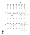
- Fig. 5 shows the knit structure, which is the knit structure of the fabric main body portion 31 of the fabric 3 and is also the ground structure of the knitted fabrics of the tightening portions 32a, 32b.
- a yarn Y1 is, for example, a nylon yarn of 56 dtex, which is caused to pass through a guide bar of a comb L1 and supplied in the direction of the arrow S to perform knitting.
- a yarn Y2 is a polyurethane yarn of 310 dtex, which is caused to pass through a guide bar of a comb L2 and supplied in the direction of the arrow S to perform knitting. All of the courses consist an insertion structure, wherein the six courses C1 through C6 consist one repeating unit R, which is expressed as "2, 2/1, 1/3, 3/1, 1/2, 2/0, 0//.”
- These yarns Y1 and Y2 are knitted at the positions of all needle points, whereby a satin ground structure of the fabric 3 is knitted.
- This state is shown as an organizational diagram in Fig. 6 .
- the ground structure of the fabric 3 is not limited to those shown in Figs. 5 and 6 , and thus 1/1 tricot structure, 1/2 tricot structure, 1/3 tricot structure, structure having a combination of these structures, a combination of a chain structure and an insertion structure, or other appropriate structure can be adopted.
- the thickness or types of the yarns can also be selected appropriately.
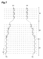
- Fig. 7 is an organizational diagram showing how the yarns are knitted into the ground structure in order to reinforce the tightening force.
- Yarn Y3 and yarn Y4 each are a FTY 22t x 33t elastic yarn obtained by twisting a 33 dtex nylon yarn around a 22 dtex polyurethane yarn as a wick.
- the reason for using such yarn having a polyurethane yarn and a nylon yarn entwined with each other is to reduce the difference in dyeing effect between the fabric main body portion and this yarn, which is caused by the fact that the dyeing characteristics of the polyurethane yarn is poorer than those of the nylon yarn.
- a yarn of an appropriate type and thickness can be adopted as the yarn Y3 and yarn Y4.
- a thick yarn can be adopted as the yarn Y3 and yarn Y4 for obtaining stronger tightening force.
- the yarn Y3 is caused to pass through the guide bar of a comb L3, supplied in the direction of the arrow S, and knitted.
- the yarn Y4 is caused to pass through the guide bar of a comb L4, supplied in the direction of the arrow S, and knitted.
- the yarn Y4 shown in Fig. 7 is knitted into all wales in the belt of the tightening portion 32a formed continuously from the bottom to the top in the order of the weak tightening portion 322a, strong tightening portion 321a, weak tightening portion 322a, strong tightening portion 321a, and weak tightening portion 322a, as shown in Fig. 3 .
- yarns Y3 and Y4 are knitted simultaneously with the yarn Y1 and the yarn Y2 that form the ground structures, but these yarns are explained separately for the convenience of explanation.
- the yarn Y3 and yarn Y4 in the courses of a range A1 are both knitted into the ground structure knitted by the yarns Y1 and Y2, in the form of the insertion structure "1, 1/0, 0//" where a yarn moves between only two adjacent needle space portions alternately.
- This section corresponds to the weak tightening portions 322a and 322b located at the bottom of the fabric 3 shown in Fig. 3 , wherein the yarn Y3 is knitted into the weak tightening portion 322b and the yarn Y4 into the weak tightening portion 322a.
- the structures of the yarn Y3 and yarn Y4 are the insertion structures where a yarn moves between only the adjacent two needle space portions alternately, the quantity of required yarns is small and the quantity of yarns to be supplied is controlled to a small quantity by an electronic control device. Since the yarn Y3 and yarn Y4 are knitted into the ground structure knitted by the yarn Y1 and yarn Y2, the weak tightening portions 322a, 322b are formed into fabrics denser than the peripheral fabric main body portion 31 formed only by the ground structures and thus generate a strong tightening force.
- the weak tightening portions 322a, 322b have low density and relatively small tightening force and thus are not as visually apparent as the strong tightening portions 321a, 321b.
- the yarn Y3 and yarn Y4 gradually shift so as to approach each other on the basis of the chain structures in the courses within a range A2. Then, in the courses within a range A3, the yarn Y3 and yarn Y4 are formed by only the linear chain structures that are parallel to each other. Although not illustrated in Fig. 7 , in the courses within the range next to the range A3, as opposed to A2, the structure to shift in the direction spreading each other on the basis of the chain structures is continued.
- the range from A2 to this range corresponds to the substantially X-shaped strong tightening portions 321a, 321b shown in Fig.
- the yarn Y3 is knitted into the strong tightening portion 321b, and the yarn Y4 into the strong tightening portion 321a. Since the yarn Y3 and yarn Y4 configure the looping structures, the quantity of required yarns is large, and the quantity of yarns to be supplied is controlled to a large quantity by the electronic control device. Therefore, in the strong tightening portions 321a, 321b, fabrics are formed into denser fabrics, compared to not only the peripheral fabric main body portion 31 but also the weak tightening portions 322a, 322b.
- the chain structures are strongly apt to prevent the extension (reduce the degree of elongation) in the warp direction of the fabric (knitting direction, which is the direction of the arrow S), compared to the other structures. Therefore, combined with the fact that the fabrics are formed densely, the strong tightening portions 321a, 321b can generate a strong tightening force.
- the yarn Y3 and yarn Y4 are knitted into the weak tightening portions 322a, 322b, in the form of the insertion structures similar to those formed in the range A1.
- courses subsequent to A2 continue in the form of the chain structures knitted into the part configured by the strong tightening portions 321a, 321b shown at the top of Fig. 3 , and finally the courses end up with the insertion structures knitted into the part configured by short weak tightening portions 322a, 322b.
- the yarn Y3 and yarn Y4 are substantially symmetry with respect to a line.
- Fig. 7 illustrates only one of each yarns Y3 and Y4 and a part of each of the ranges A1, A2 and A3, the same shapes as those of the tightening portions 32a, 32b shown in Fig. 3 are formed by drawing, in Fig. 7 , all of the yarns Y3 and Y4, which are knitted into the tightening portions 32a and 32b respectively, throughout the whole ranges.
- the insertion structures formed in the range A1 and the like are not limited to the insertion structure of "1, 1/0, 0//" where a yarn moves between only two adjacent needle space portions alternately as shown in Fig. 7 , and thus may be the insertion structure of "2, 2/0, 0//" shown by a yarn Y5, for example, or may be the insertion structures shown by a yarn Y6 and a yarn Y7, as shown in Fig. 8 .
- Increasing the swing width of the inserted yarns in the horizontal direction (course direction) thereof increases the quantity of yarns used and the tightening force of the weak tightening portions 322a, 322b to be formed.
- appropriate looping structures may be incorporated in accordance with the insertion structures.
- the proportion of the looping structures the larger the quantity of yarns used and the greater the tightening force of the weak tightening portions 322a, 322b to be formed.
- the proportion of the looping structures of the weak tightening portions 322a, 322b is smaller than the looping structures included in the strong tightening forces 321a, 321b formed in the same belt, and the tightening force of the weak tightening portions 322a, 322b is relatively weaker than that of the strong tightening portions 3 21 a, 321b.
- the looping structures formed in the ranges A2, A3 and the like may not necessarily be based on the chain structures shown in Fig. 7 , but also may be based on the 1/1 tricot structure shown with a yarn Y9 in Fig. 9 or the structure having a combination of an open stitch and a closed stitch, as shown with a yarn Y10.
- the insertion structures may be combined based on the looping structures as shown with yarns Y11, Y12.
- the proportion of the insertion structures the lower the quantity of yarns used and the weaker the tightening force.
- the proportion of the insertion structures of the strong tightening portions 321a, 321b is lower than that of the weak tightening portions 322a, 322b formed in the same belt, and the tightening force of the strong tightening portions 321, 321b is relatively stronger than that of the weak tightening portions 322a, 322b.
- the above has described the simple situation where the amount of yarns to be supplied is controlled according to the structure type only, but the structure type does not always determine the amount of yarns used, or the tightening force is not always determined from the amount yarns used.
- the insertion structure of "1, 1/0, 0//" in which the swing width is small can adjust the amount of yarns to be supplied to be larger than that of an insertion structure having a larger swing width.
- the increase of the amount of yarns to be supplied does not necessarily lead to the increase of the tightening force.
- devising the structures of the weak tightening portions 322a, 322b and the structures of the strong tightening portions 321a, 321b can provide appropriate tightening force to these tightening portions. Therefore, the difference in tightening force between the strong tightening portions 322a, 322b and the fabric main body portion 31 and the difference in tightening force between the strong tightening portions 322a, 322b and the weak tightening portions 321a, 321b can be designed appropriately.
- the tightening force of the strong tightening portions 322a, 322b can be changed in a multistage manner in the knitting direction and, similarly, the tightening force of the weak tightening portions 321a, 321b can be changed in a multistage manner in the knitting direction.
- the wearing pressure of the strong tightening portions 321a, 321b is low, but the wearer feels tightness when the wearing pressure of the strong tightening portions 321a, 321b is high.
- the wearing pressure of the strong tightening portions 321a, 321b and the wearing pressure of the section that does not form the tightening portions differ from each other by at least 10 gf/cm2. Note that the wearing pressures were measured with a contact pressure measuring instrument manufactured by AMI Co., Ltd. (Airpack type.
- the waist of the dummy the length therefrom to the floor is 553 mm, the peripheral diameter is 650 mm, the lateral diameter is 230 mm, and the thickness is 165 mm.
- the hip of the dummy the length therefrom to the floor is 385 mm, the peripheral diameter is 895 mm, the lateral diameter is 320 mm, and the thickness is 215 mm.
- the length therefrom to the floor is 285 mm
- the peripheral diameter is 520 mm
- the lateral diameter is 150 mm
- the thickness is 170 mm.
- the length therefrom to the floor is 435 mm
- the peripheral diameter is 845 mm
- the lateral diameter is 305 mm
- the thickness is 202 mm.
- the yarn Y3 and the yarn Y4 for reinforcing the tightening force are knitted continuously into the common ground structures in the belt-like tightening portions 32a, 32b, and the strong tightening portions 321a, 321b are formed mainly by the looping structures, while the weak tightening portions 322a, 322b are formed mainly by the insertion structures.
- the strong tightening portions 321a, 321b are formed into a desired shape in an appropriate position of the knitted fabric, and a sufficient difference in the tightening force between the strong tightening portions 321a, 321b and the fabric main body portion 31 except the strong tightening portion and also between the strong tightening portions 321a, 321b and the weak tightening portions 322a, 322b can be obtained.
- the chain structure is strongly apt to prevent the extension (reduce the degree of elongation) in the warp direction of the fabric. Therefore, combined with the fact that the fabrics are formed densely, the strong tightening portions 321a, 321b can generate a strong tightening force. Moreover, the strong tightening portions 321a, 321b are formed into the shape of an X having the part inclined in the longitudinal directions of the weak tightening portions 322a, 322b.
- the two strong tightening portions 321a, 321b concentrate on the central parts of the thighs of the wearer without compressing the thighs in the form of a ring, and thereby a tightening force can be dispersed in horizontal and vertical directions.
- the tightening force can be set to a predetermined amount by changing the structures of the yarns Y3 and Y4 for reinforcing the tightening force of the strong tightening portions 321a, 321b, which are based on the chain structure, to the other structure or by combining the structures of the yarns Y3 and Y4 with the insertion structures.
- the tightening force can be set to a predetermined amount by increasing the swing width in the horizontal direction from the insertion structures of "1, 1/0, 0//" or by combining the structures of the yarns Y3 and Y4 with the insertion structures.
- the tightening force of the strong tightening portions 322a, 322b can be changed in a multistage manner in the knitting direction and, similarly, the tightening force of the weak tightening portions 321a, 321b can be changed in a multistage manner in the knitting direction, by changing the knit structures formed by the yarns Y3 and Y4 for reinforcing the tightening force of the tightening portions 32a, 32b.
- the garment of the present invention that is attached tightly to a body is not limited to the one described above.
- the belt-like tightening portions 32a, 32b may be formed into various shapes by the strong tightening portions 321a, 321b and weak tightening portions 322a, 322b shown in (A) through (H) of Fig. 10 .
- a thigh can be tightened strongly in the form of a ring.
- the strong tightening portions 321a, 321b are formed into an appropriate shape so as to have the parts inclined in the longitudinal directions of the weak tightening portions 322a, 322b as shown in the diagrams other than (F) of Fig. 10 , so that desired direction and position of the tightening force of the strong tightening portions 321a, 321b can be obtained. Furthermore, a single belt-like tightening portion 32a may be obtained without combining the two belt-like tightening portions 32a, 32b, as shown in an example in (H).
- Fig. 11 is a perspective view showing an example in which the present invention is applied to other section of the girdle 1, wherein the girdle 1 is viewed from the front.
- One tightening portion 32a is formed in the abdominal cloth 4.
- a tightening force can be added to the abdomen of the wearer so as to prevent the abdomen from bulging.
- Fig. 12 is a perspective view showing another example of application of the present invention, wherein the girdle 1 is viewed from behind.
- Fig. 13 is a perspective view showing yet another example of application of the present invention, wherein a short girdle 5 is viewed from behind.
- the tightening portion is formed by one belt-like tightening portion 32a.
- the strong tightening portion 321a is formed in a section corresponding to the lower part of the bulge of the hip of the wearer, whereby the hip of the wearer can be lifted up to compensate the body shape of the wearer.
- the strong tightening portion 321a is similarly formed in the section corresponding to the lower part of the bulge of the hip of the wearer, but the strong tightening portion 321a and the weak tightening portion 322a are formed alternately in a multistage manner, and the length in a belt direction of the strong tightening portion 321a is increased at a lower part of the center of the hip to adjust the strength of the tightening force in the belt direction in a multistage manner. Accordingly, the tightening force can be applied gradually from the section requiring a strong tightening force toward a section that does not require a strong tightening force. Furthermore, although not shown, the strong tightening portion can be formed in a section between a side portion and a back portion of a brassiere, or a side portion and a rear portion of a body suit.
- the shapes of the tightening portions are not limited, hence the belt-like weak tightening portions and strong tightening portions may be formed in various shapes as shown in the modifications shown in Fig. 10 .
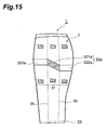
- Fig. 15 is a view in which the girdle 1 is viewed edge-on.
- the fabric main body portion 31 forming the body 2 is sectioned into knitted fabric parts that are formed respectively by two types of ground structures having different tightening forces.
- a knitted fabric part 31a positioned in the center with respect to the horizontal direction is knitted by a ground structure having a relatively strong tightening force, and knitted fabric parts 31b positioned on both sides of the knitted fabric part 31 a are knitted respectively by weak ground structures having a relatively weak tightening force.
- the weak tightening portion 322a of the single belt-like tightening portion 32a are formed at substantially right angles to borderlines 35 of the knitted fabric parts 31 a, 31b.
- the weak tightening portions 322a are formed on two sides, the right and left sides, with a step formed therein so as to overlap with the knitted fabric part 31 b having a relatively weak tightening force, and the strong tightening portion 321 a is formed between the weak tightening portions 322a so as to overlap with the knitted fabric part 31 a having a relatively strong tightening force.
- the strong tightening portion 321a is inclined such that the front side thereof is positioned upward.
- each of the weak tightening portions 322a and the respective borderlines 35 are formed at substantially right angles to each other, but may form a different crossing angle, hence the belt-like tightening portion 32a constituted by the strong tightening portion 321a and the weak tightening portions 322a may intersect with the borderlines 35.
- the position of the knitted fabric part 31b with a relatively weak tightening force overlaps with the positions of the weak tightening portions 322a
- the position of the knitted fabric part 31a with a relatively strong tightening force overlaps with the positions of the strong tightening portions 321a, but these positions may not be overlapped and the knitted fabric part 31a with a strong tightening force may overlap with at least a part of the strong tightening portion 321a.
- the overlapped parts are provided with a stronger tightening force due to the strong tightening force of the ground structures of the knitted fabric and the overlapping strong tightening portion 321a of the tightening portion 32a.
- the tightening portion 32a is positioned on an outer periphery of an upper part of a thigh of the wearer, and the strong tightening portion 321a of the tightening portion 32a is positioned in each side portion of the hip. Therefore, the section between the upper part of the thigh and the lower part of the hip of the wearer is tightened, and particularly the strong tightening portion 321 a prevents the both sides of the hip from bulging, whereby the body shape is fixed.
- the entire side portion of the hip can be tightened.
- the strong tightening portion 321a is inclined upward or downward and has the part inclined in the longitudinal direction of the weak tightening portion 322a, the entire tightening portion 32a is prevented from being formed into a ring of the same circumference, and particularly the tightness generated by the strong tightening portion 321a can be alleviated.
- Fig. 16 is a schematic diagram showing one unit of fabric 3 for creating the body 2 on the left side of the girdle 1.
- the fabric 3 is a warp knitted fabric knitted by yarns supplied in the direction shown by the arrow S, and has the one belt-like tightening portions 32a formed at a part of the fabric main body portion 31 configured by a ground structure.
- the tightening portion 32a is configured by the strong tightening portion 321a and the weak tightening portion 322a as described with reference to Fig. 15 .
- the hems 33 for preventing raveling of the yarns are formed at upper and lower edges.
- the left body 2 is cut from the fabric shown in Fig. 16
- the right body 2 is cut from a fabric symmetric with the one shown in Fig. 16
- these bodies 2 an abdominal cloth 4 and a crotch are stitched together, and eight units of the fabric 3 are knitted integrally by the warp-knitting machine.
- Fig. 16 The major difference between Fig. 16 and each of Fig. 1 through Fig. 3 is that in Fig. 16 the ground structure of the range between the right end of the fabric 3 and the borderline 35 is knitted by a 1/2 tricot structure shown in, for example, the left side of Fig. 17 , and that the subsequent range up to the left borderline 35 is knitted by a 1/3 tricot structure shown on the right side of Fig. 17 .
- the 1/3 tricot structure has a larger amount of yarns used and a relatively stronger tightening force. Note that, as with the cases shown in Fig. 1 through Fig. 7 , the yarns for reinforcing the tightening force are knitted into the fabric 3 so that the tightening portion 31 is formed along with the ground structures.
- ground structures with different tightening forces not only such 1/2 tricot structure and 1/3 tricot structure but also appropriate structures can be adopted in which, for example, a net structure (mesh structure) having low-density stitches is formed as the weak knitted fabric part 31 b having a relatively weak tightening force, and various satin structures having denser stitches are formed as the strong knitted fabric part 31a having a relatively strong tightening force.
- a net structure (mesh structure) having low-density stitches is formed as the weak knitted fabric part 31 b having a relatively weak tightening force
- various satin structures having denser stitches are formed as the strong knitted fabric part 31a having a relatively strong tightening force.
- each of the knitted fabric portions may be sectioned into four or more sections or two sections.
- the knitted structure of the tightening portion 32a may be configured in various ways as described with reference to Fig. 8 and Fig. 9 , and various shapes as illustrated in Fig. 10 can be adopted as the shape of the tightening portion.
- the tightening portion 32a configures the ground structure that is common in the knitted fabric parts 31a, 31 b of the fabric main body portion 31 that are adjacent to the tightening portion 32a and all adjacent portions.
- the ground structure of the tightening portion 32a including the strong tightening portion 321a and the weak tightening portion 322a can be configured to be the same as the ground structure of the knitted fabric part 31a having a strong tightening force.
Landscapes
- Engineering & Computer Science (AREA)
- Textile Engineering (AREA)
- Corsets Or Brassieres (AREA)
- Knitting Of Fabric (AREA)
- Professional, Industrial, Or Sporting Protective Garments (AREA)
Applications Claiming Priority (2)
| Application Number | Priority Date | Filing Date | Title |
|---|---|---|---|
| JP2005303480A JP4673182B2 (ja) | 2005-10-18 | 2005-10-18 | 衣類 |
| PCT/JP2006/320455 WO2007046298A1 (ja) | 2005-10-18 | 2006-10-13 | 衣類 |
Publications (1)
| Publication Number | Publication Date |
|---|---|
| EP1967084A1 true EP1967084A1 (en) | 2008-09-10 |
Family
ID=37962393
Family Applications (1)
| Application Number | Title | Priority Date | Filing Date |
|---|---|---|---|
| EP06821858A Withdrawn EP1967084A1 (en) | 2005-10-18 | 2006-10-13 | Garment |
Country Status (5)
| Country | Link |
|---|---|
| US (1) | US20090172858A1 (ja) |
| EP (1) | EP1967084A1 (ja) |
| JP (1) | JP4673182B2 (ja) |
| TW (1) | TW200727798A (ja) |
| WO (1) | WO2007046298A1 (ja) |
Cited By (2)
| Publication number | Priority date | Publication date | Assignee | Title |
|---|---|---|---|---|
| CN103826485A (zh) * | 2011-09-30 | 2014-05-28 | 株式会社华歌尔 | 衣服的端部构造、下装、带罩杯的衣服及具有修整功能的衣服的构造 |
| US9644293B2 (en) | 2011-03-28 | 2017-05-09 | Wacoal Corp. | Knitted fabric and garment using the same |
Families Citing this family (20)
| Publication number | Priority date | Publication date | Assignee | Title |
|---|---|---|---|---|
| US7996924B2 (en) | 2007-05-31 | 2011-08-16 | Nike, Inc. | Articles of apparel providing enhanced body position feedback |
| US8336118B2 (en) | 2007-05-31 | 2012-12-25 | Nike, Inc. | Articles of apparel providing enhanced body position feedback |
| US7934267B2 (en) * | 2007-05-31 | 2011-05-03 | Nike, Inc. | Articles of apparel providing enhanced body position feedback |
| WO2009034621A1 (ja) * | 2007-09-12 | 2009-03-19 | Wacoal Corp. | 運動用股付き衣類 |
| JP5412054B2 (ja) | 2008-05-02 | 2014-02-12 | 株式会社ワコール | 衣料用経編地及びその製造方法並びに衣料用経編地の編構造 |
| JP4971473B2 (ja) * | 2010-02-19 | 2012-07-11 | ウラベ株式会社 | 伸縮性経編地とその用途 |
| JP2012136813A (ja) * | 2010-12-09 | 2012-07-19 | Yoshida Sangyo Kk | 伸縮パワー強化部ないし非伸縮性付与部からなる補強部を有する経編衣料 |
| US9345275B2 (en) | 2011-02-18 | 2016-05-24 | Nike, Inc. | Lower body garment with elasticity-reducing panel |
| JPWO2013046457A1 (ja) * | 2011-09-30 | 2015-03-26 | 株式会社ワコール | 衣類の端部構造、ボトム衣類、カップ付き衣類、及び補整機能を有する衣類の構造 |
| US9456641B1 (en) | 2011-10-06 | 2016-10-04 | Francesco Mignone | Yoga article of clothing and method of use thereof |
| JP6168737B2 (ja) * | 2012-06-27 | 2017-07-26 | 北陸エステアール協同組合 | 衣類用伸縮性経編地、衣類用伸縮性経編地の製造方法、衣類の製造方法 |
| JP6177506B2 (ja) * | 2012-06-27 | 2017-08-09 | 北陸エステアール協同組合 | 伸縮性経編地の製造方法、衣類の製造方法 |
| DE102012216180B4 (de) * | 2012-09-12 | 2026-05-07 | Falke Kgaa | Beinbekleidungsstück |
| JP6123207B2 (ja) * | 2012-09-27 | 2017-05-10 | 株式会社ワコール | カップ部を有する衣類 |
| US20150264980A1 (en) * | 2014-03-18 | 2015-09-24 | William C. Tally | Posture protector devices, systems and methods |
| GB2533077B (en) | 2014-08-22 | 2017-12-06 | Speedo Int Ltd | Swimming garments |
| US11078607B2 (en) * | 2017-03-23 | 2021-08-03 | Delta Galil Industries Ltd. | Clothing articles having encapsulation zones, and system and method of producing such clothing articles |
| US10478327B2 (en) | 2018-02-22 | 2019-11-19 | Ifgcure Holdings, Llc | Postural recovery garment device system |
| CN109885935B (zh) * | 2019-02-21 | 2022-12-27 | 东华大学 | 一种基于假人测试的个体服装压力测量方法 |
| CN110387638A (zh) * | 2019-07-29 | 2019-10-29 | 互太(番禺)纺织印染有限公司 | 一种免缝边经编弹性织物及其编织工艺和用途 |
Family Cites Families (24)
| Publication number | Priority date | Publication date | Assignee | Title |
|---|---|---|---|---|
| US3413824A (en) * | 1965-02-19 | 1968-12-03 | Swiss Knitting Company | Method for the spot shaping of knit fabrics and resultant fabrics produced thereby |
| US4103485A (en) * | 1975-09-01 | 1978-08-01 | Gold-Zack Werke Ag | Elastic warp-knit fabric |
| US4325379A (en) * | 1980-12-17 | 1982-04-20 | Ozbey Ahmet M | Derriere exerciser |
| US5109546A (en) * | 1991-06-10 | 1992-05-05 | Dicker Timothy P | Exercise suit with resilient reinforcing |
| US5611722A (en) * | 1995-02-03 | 1997-03-18 | Alba-Waldensian, Inc. | Panty having knit-in buttock lift and separation |
| US5954564A (en) * | 1995-05-25 | 1999-09-21 | Warnaco, Inc. | Undergarment with natural feeling buttock support |
| FR2751668B1 (fr) * | 1996-07-26 | 1998-09-11 | Dim Sa | Procede et tricotage d'articles de bonneterie, et articles, notamment collants, realises selon ce procede |
| JP3012819B2 (ja) * | 1997-04-01 | 2000-02-28 | 株式会社ワコール | 下肢部保護衣料 |
| CA2235561C (en) * | 1997-04-22 | 2003-01-14 | Robert Balit | Swim and body suit support system |
| US6231488B1 (en) * | 1997-09-15 | 2001-05-15 | Timothy P. Dicker | Aerobic exercise garment |
| JP4187348B2 (ja) * | 1999-04-12 | 2008-11-26 | 旭化成せんい株式会社 | 異なる弾性力を有する複数の編地片から成る弾性経編地 |
| JP2001049501A (ja) * | 1999-08-06 | 2001-02-20 | Triumph International (Japan) Ltd | 下着の開口部 |
| US6430753B2 (en) * | 1999-12-30 | 2002-08-13 | Intermarketing Express Inc | Reinforced undergarment |
| TW475887B (en) * | 2000-04-20 | 2002-02-11 | Wacoal Corp | Leg portions supporting wear |
| JP2002324003A (ja) * | 2001-04-25 | 2002-11-08 | Casio Comput Co Ltd | 文書管理システムおよび文書管理方法 |
| JP4210062B2 (ja) * | 2002-01-18 | 2009-01-14 | ウラベ株式会社 | 伸縮性経編地 |
| US6874337B2 (en) * | 2002-06-05 | 2005-04-05 | Mizuno Corporation | Underpant garment |
| DE10314423B3 (de) * | 2003-03-28 | 2004-09-02 | Schroth Safety Products Gmbh | Anordnung zur Positionierung der Schultergurte eines Sicherheitsgurts in Längsrichtung der Schenkel eines U-förmigen Schulterjochs |
| JP3607274B2 (ja) * | 2003-04-23 | 2005-01-05 | 株式会社ワコール | 衣料 |
| JP4206295B2 (ja) * | 2003-05-13 | 2009-01-07 | 株式会社ワコール | 身体に密着する衣料 |
| PL1675484T3 (pl) * | 2003-10-15 | 2011-09-30 | Thomas Lutz | Ubiór |
| JP4018682B2 (ja) * | 2004-09-21 | 2007-12-05 | 株式会社アシックス | スパッツ |
| US7260961B1 (en) * | 2006-11-02 | 2007-08-28 | Amanda Kennedy | Circularly knit undergarment having knit-in support panels and derriere cup fullness |
| JP4024287B1 (ja) * | 2007-02-27 | 2007-12-19 | 株式会社エヌ・エル・シーコーポレーション | 腰痛体操の効果が期待できるウエアー |
-
2005
- 2005-10-18 JP JP2005303480A patent/JP4673182B2/ja not_active Expired - Fee Related
-
2006
- 2006-10-13 EP EP06821858A patent/EP1967084A1/en not_active Withdrawn
- 2006-10-13 US US12/090,401 patent/US20090172858A1/en not_active Abandoned
- 2006-10-13 WO PCT/JP2006/320455 patent/WO2007046298A1/ja not_active Ceased
- 2006-10-17 TW TW095138200A patent/TW200727798A/zh unknown
Non-Patent Citations (1)
| Title |
|---|
| See references of WO2007046298A1 * |
Cited By (2)
| Publication number | Priority date | Publication date | Assignee | Title |
|---|---|---|---|---|
| US9644293B2 (en) | 2011-03-28 | 2017-05-09 | Wacoal Corp. | Knitted fabric and garment using the same |
| CN103826485A (zh) * | 2011-09-30 | 2014-05-28 | 株式会社华歌尔 | 衣服的端部构造、下装、带罩杯的衣服及具有修整功能的衣服的构造 |
Also Published As
| Publication number | Publication date |
|---|---|
| JP4673182B2 (ja) | 2011-04-20 |
| JP2007113125A (ja) | 2007-05-10 |
| TW200727798A (en) | 2007-08-01 |
| US20090172858A1 (en) | 2009-07-09 |
| WO2007046298A1 (ja) | 2007-04-26 |
Similar Documents
| Publication | Publication Date | Title |
|---|---|---|
| EP1967084A1 (en) | Garment | |
| AU773659B2 (en) | An undergarment | |
| US6401497B1 (en) | Garment with figure control or muscle support function | |
| KR101396106B1 (ko) | 의류용 편성포 | |
| JP4055099B2 (ja) | サポータと、その製造方法 | |
| JP4368102B2 (ja) | 身体に密着する衣類 | |
| CN103189557B (zh) | 织物以及带裆服装 | |
| JP4457141B2 (ja) | 部分低伸長伸縮性経編地 | |
| KR20130135747A (ko) | 편성포의 편성방법 | |
| JP3817690B2 (ja) | 衣料用の伸縮性経編地 | |
| EP3165648A1 (en) | Tubular knitted fabric provided with tightening portion and knitting method therefor | |
| TWI437964B (zh) | Warp knitted fabric and cloth with the warp knitted fabric | |
| JP4468869B2 (ja) | 部分伸縮変化ラッセルレース編地及びその製造方法 | |
| JP3461316B2 (ja) | 体型補整機能を有する衣類 | |
| EP2208814A1 (en) | End-connecting method for doubly-cylindrical fabric | |
| JP2006233372A (ja) | インナー・ウェア | |
| US20150292129A1 (en) | Stretchable warp knit fabric for clothes, bottom garment, and tubular clothes | |
| JP5323387B2 (ja) | 編成組織及び衣服 | |
| JP4054710B2 (ja) | 端末編組織および該端末編組織を備えた衣類 | |
| JP7822606B2 (ja) | 経編生地及びサポータ | |
| JP3796619B2 (ja) | レース編地とその製造方法 | |
| JP2009215696A (ja) | 身体に密着する衣類 | |
| CN111218761B (zh) | 编织物的编织方法及编织物 | |
| US20250288467A1 (en) | Engineered knitted garment having integrated compression zones | |
| JP3125958U (ja) | 経編レース地を用いた衣類 |
Legal Events
| Date | Code | Title | Description |
|---|---|---|---|
| PUAI | Public reference made under article 153(3) epc to a published international application that has entered the european phase |
Free format text: ORIGINAL CODE: 0009012 |
|
| STAA | Information on the status of an ep patent application or granted ep patent |
Free format text: STATUS: THE APPLICATION HAS BEEN WITHDRAWN |
|
| 17P | Request for examination filed |
Effective date: 20080421 |
|
| AK | Designated contracting states |
Kind code of ref document: A1 Designated state(s): BE FR NL |
|
| 18W | Application withdrawn |
Effective date: 20080828 |