EP1967228A2 - Procédé et appareil d'étalonnage d'un système de traitement de thérapie à rayonnement - Google Patents
Procédé et appareil d'étalonnage d'un système de traitement de thérapie à rayonnement Download PDFInfo
- Publication number
- EP1967228A2 EP1967228A2 EP08005758A EP08005758A EP1967228A2 EP 1967228 A2 EP1967228 A2 EP 1967228A2 EP 08005758 A EP08005758 A EP 08005758A EP 08005758 A EP08005758 A EP 08005758A EP 1967228 A2 EP1967228 A2 EP 1967228A2
- Authority
- EP
- European Patent Office
- Prior art keywords
- radiation
- measurement device
- data
- commissioning
- radiation source
- Prior art date
- Legal status (The legal status is an assumption and is not a legal conclusion. Google has not performed a legal analysis and makes no representation as to the accuracy of the status listed.)
- Withdrawn
Links
- 238000000034 method Methods 0.000 title claims abstract description 32
- 238000001959 radiotherapy Methods 0.000 title claims description 22
- 230000005855 radiation Effects 0.000 claims abstract description 79
- 238000005259 measurement Methods 0.000 claims abstract description 30
- XLYOFNOQVPJJNP-UHFFFAOYSA-N water Substances O XLYOFNOQVPJJNP-UHFFFAOYSA-N 0.000 claims abstract description 21
- 230000035515 penetration Effects 0.000 claims description 3
- PCHJSUWPFVWCPO-UHFFFAOYSA-N gold Chemical compound [Au] PCHJSUWPFVWCPO-UHFFFAOYSA-N 0.000 description 13
- 230000008569 process Effects 0.000 description 11
- 229910052782 aluminium Inorganic materials 0.000 description 10
- XAGFODPZIPBFFR-UHFFFAOYSA-N aluminium Chemical compound [Al] XAGFODPZIPBFFR-UHFFFAOYSA-N 0.000 description 10
- 238000000275 quality assurance Methods 0.000 description 8
- 239000000463 material Substances 0.000 description 5
- QRYFCNPYGUORTK-UHFFFAOYSA-N 4-(1,3-benzothiazol-2-yldisulfanyl)morpholine Chemical compound C1COCCN1SSC1=NC2=CC=CC=C2S1 QRYFCNPYGUORTK-UHFFFAOYSA-N 0.000 description 4
- 238000002721 intensity-modulated radiation therapy Methods 0.000 description 4
- 238000010521 absorption reaction Methods 0.000 description 3
- 238000004458 analytical method Methods 0.000 description 3
- 238000002591 computed tomography Methods 0.000 description 3
- 230000008878 coupling Effects 0.000 description 3
- 238000010168 coupling process Methods 0.000 description 3
- 238000005859 coupling reaction Methods 0.000 description 3
- 230000000694 effects Effects 0.000 description 3
- 210000001519 tissue Anatomy 0.000 description 3
- 206010028980 Neoplasm Diseases 0.000 description 2
- 230000008859 change Effects 0.000 description 2
- 229910003460 diamond Inorganic materials 0.000 description 2
- 239000010432 diamond Substances 0.000 description 2
- 230000007246 mechanism Effects 0.000 description 2
- 229920003023 plastic Polymers 0.000 description 2
- 239000004033 plastic Substances 0.000 description 2
- 238000002560 therapeutic procedure Methods 0.000 description 2
- 210000004204 blood vessel Anatomy 0.000 description 1
- 210000000988 bone and bone Anatomy 0.000 description 1
- 238000002725 brachytherapy Methods 0.000 description 1
- 230000002508 compound effect Effects 0.000 description 1
- 238000010276 construction Methods 0.000 description 1
- 238000010894 electron beam technology Methods 0.000 description 1
- 230000008713 feedback mechanism Effects 0.000 description 1
- 238000003384 imaging method Methods 0.000 description 1
- 230000002452 interceptive effect Effects 0.000 description 1
- 230000000670 limiting effect Effects 0.000 description 1
- 238000004519 manufacturing process Methods 0.000 description 1
- 229910052751 metal Inorganic materials 0.000 description 1
- 239000002184 metal Substances 0.000 description 1
- 150000002739 metals Chemical class 0.000 description 1
- 238000009203 neutron therapy Methods 0.000 description 1
- 210000000056 organ Anatomy 0.000 description 1
- 230000036961 partial effect Effects 0.000 description 1
- 238000002727 particle therapy Methods 0.000 description 1
- 238000002661 proton therapy Methods 0.000 description 1
- 230000002829 reductive effect Effects 0.000 description 1
- 230000004044 response Effects 0.000 description 1
- 238000013515 script Methods 0.000 description 1
- 210000004872 soft tissue Anatomy 0.000 description 1
- 230000003068 static effect Effects 0.000 description 1
- 238000012360 testing method Methods 0.000 description 1
- 238000012549 training Methods 0.000 description 1
- 238000012546 transfer Methods 0.000 description 1
- 230000001131 transforming effect Effects 0.000 description 1
Images




Classifications
-
- A—HUMAN NECESSITIES
- A61—MEDICAL OR VETERINARY SCIENCE; HYGIENE
- A61N—ELECTROTHERAPY; MAGNETOTHERAPY; RADIATION THERAPY; ULTRASOUND THERAPY
- A61N5/00—Radiation therapy
- A61N5/10—X-ray therapy; Gamma-ray therapy; Particle-irradiation therapy
-
- A—HUMAN NECESSITIES
- A61—MEDICAL OR VETERINARY SCIENCE; HYGIENE
- A61N—ELECTROTHERAPY; MAGNETOTHERAPY; RADIATION THERAPY; ULTRASOUND THERAPY
- A61N5/00—Radiation therapy
- A61N5/10—X-ray therapy; Gamma-ray therapy; Particle-irradiation therapy
- A61N5/1048—Monitoring, verifying, controlling systems and methods
-
- A—HUMAN NECESSITIES
- A61—MEDICAL OR VETERINARY SCIENCE; HYGIENE
- A61N—ELECTROTHERAPY; MAGNETOTHERAPY; RADIATION THERAPY; ULTRASOUND THERAPY
- A61N5/00—Radiation therapy
- A61N5/10—X-ray therapy; Gamma-ray therapy; Particle-irradiation therapy
- A61N5/1048—Monitoring, verifying, controlling systems and methods
- A61N5/1075—Monitoring, verifying, controlling systems and methods for testing, calibrating, or quality assurance of the radiation treatment apparatus
- A61N2005/1076—Monitoring, verifying, controlling systems and methods for testing, calibrating, or quality assurance of the radiation treatment apparatus using a dummy object placed in the radiation field, e.g. phantom
-
- A—HUMAN NECESSITIES
- A61—MEDICAL OR VETERINARY SCIENCE; HYGIENE
- A61N—ELECTROTHERAPY; MAGNETOTHERAPY; RADIATION THERAPY; ULTRASOUND THERAPY
- A61N5/00—Radiation therapy
- A61N5/10—X-ray therapy; Gamma-ray therapy; Particle-irradiation therapy
- A61N5/1042—X-ray therapy; Gamma-ray therapy; Particle-irradiation therapy with spatial modulation of the radiation beam within the treatment head
-
- A—HUMAN NECESSITIES
- A61—MEDICAL OR VETERINARY SCIENCE; HYGIENE
- A61N—ELECTROTHERAPY; MAGNETOTHERAPY; RADIATION THERAPY; ULTRASOUND THERAPY
- A61N5/00—Radiation therapy
- A61N5/10—X-ray therapy; Gamma-ray therapy; Particle-irradiation therapy
- A61N5/1048—Monitoring, verifying, controlling systems and methods
- A61N5/1075—Monitoring, verifying, controlling systems and methods for testing, calibrating, or quality assurance of the radiation treatment apparatus
Definitions
- This invention relates to a radiation therapy imaging and treatment system. More specifically, the invention relates to structure within the system that is utilized to calibrate the system, and to a method of commissioning or tuning the system.
- IMRT Intensity modulated radiation therapy
- a radiation source external to the patient treats internal tumors.
- the external source is normally collimated to direct a beam only to the tumorous site.
- the radiation source consists of either high-energy X-rays, electrons from certain linear accelerators, or gamma rays from highly focused radioisotopes, though other types of radiation sources are possible:
- the system itself needs to be commissioned properly at the outset and needs to be continuously monitored to ensure that the system is operating within the appropriate, and expected, parameters.
- the system characteristics are measured and compared against predetermined standards to configure the system and to ensure that the system is working within expected parameters. Commissioning includes consideration of total machine calibration, tuning the geometry of the beam delivered, and ensuring that the output and energy everywhere in the beam is equal, among other things.
- individual systems are not calibrated with respect to each other, such that, in a way, each individual system stands alone in that variations in beam shape, strength, etc. can vary between machines.
- Each system is tuned to be within a manufacturing window, and a unique planning station model is generated. In effect, with each commissioning, you change the model to fit the machine.
- the present invention provides a radiation therapy treatment system that allows for easy calibration of the system with respect to a known set of standards, a.k.a. a "gold standard.”
- the gold standard values can be determined in various ways, but are conventionally done using a water tank to produce the known attenuation results used to set the gold standard.
- Tuning machines to be dosimetrically equivalent is sometimes referred to as "twinning,” and the resulting machines that are tuned to the gold standard are considered “twins.” Because the tolerances of the systems stay the same from system to system, it is also possible to easily transfer patients from treatment on any individual system to another system without interfering with the patient's treatment plan. Tuning and commissioning becomes substantially automatic, and the machine can be changed to fit the model.
- the invention provides a radiation therapy treatment system.
- the system includes a radiation source operable to produce a beam of radiation, a gantry, and a measurement device coupled to the gantry.
- the measurement device includes a multidimensional scanning arm and a detector operable to receive radiation from the radiation source.
- the system also includes an attenuation block coupled to a portion of the system.
- the attenuation block may be movable, in one embodiment, into and out of the path of the radiation beam produced by the radiation source.
- the attenuation block comprises a plurality of aluminum plates coupled together to form a wedge that is substantially step-shaped. Radiation passed through the attenuation block is used to calibrate components of the system.
- the attenuation block may not be comprised of water.
- the attenuation block may be comprised of aluminum, or of plastic.
- the attenuation block may be substantially step-shaped, and/or may comprise a plurality of plates coupled together to form a wedge.
- the plates may be of substantially uniform thickness and the thickness of each plate may be varied to adjust for beam strength.
- the scanning arm may move in any combination of the x, y, and z directions.
- the detector may be an ion chamber, and may include multiple ion chambers.
- the ion chambers may be arranged in one of a grid, an array, or a volume.
- the detector may include one of a diode detector or a diamond detector, and may include a plurality of detectors.
- the plurality of detectors may be arranged in one of a grid, an array, or a volume.
- the measurement device may include a plurality of detectors.
- the radiation therapy treatment system may, further comprise an adjustment bracket coupled to the radiation source, wherein the adjustment bracket is operable to adjust the position of the radiation source in both first and second directions, and wherein the movement of the radiation source in each of the first and second directions is independent of the movement in the other of the first and second directions.
- the system may have a unified control system for the scanning arm and the gantry. The scanning arm may not be in contact with water.
- the invention provides a method of commissioning a radiation therapy system to a previously defined standard.
- the radiation therapy system includes a measurement device coupled to a gantry, and a radiation source operable of producing radiation.
- the method includes the acts of generating radiation with the radiation source, passing the radiation through an attenuation block, receiving the radiation with the measurement device, generating data from the radiation received, and commissioning the system using the generated data to match system characteristics to the previously defined standard.
- the method also includes positioning the measurement device such that it is not in contact with water.
- Fig. 1 is a perspective view of a radiation therapy treatment system.
- Fig. 2 is a perspective view of a multi-leaf collimator that can be used in the radiation therapy treatment system illustrated in Fig. 1 .
- Fig. 3 is perspective view of a twinning arm for use in the radiation therapy system of Fig. 1 .
- Fig. 4 is a perspective view of the twinning arm of Fig. 3 coupled to a gantry of the system of Fig. 1 .
- Fig. 5 is a perspective view of an attenuation block coupled to the system of Fig. 1 .
- Fig. 6 is a screen shot of a representative user interface generated by software according to the invention.
- Fig. 7 is a screen shot of a portion of the user interface of Fig. 6 , illustrating the component input features.
- Fig. 8 is a graphical representation of data generated by the software of the invention illustrating the longitudinal profile data.
- Fig. 9 is a graphical representation of data generated by the software of the invention illustrating the transverse profile data.
- Fig. 10 is a graphical representation of data generated by the software of the invention illustrating the stepwise attenuation block data.
- Fig. 11 is a perspective view of a linac mounting bracket according to the invention.
- embodiments of the invention include hardware, software, and electronic components or modules that, for purposes of discussion, may be illustrated and described as if the majority of the components were implemented solely in hardware.
- the electronic based aspects of the invention maybe implemented in software.
- a plurality of hardware and software based devices, as well as a plurality of different structural components may be utilized to implement the invention.
- the specific mechanical configurations illustrated in the drawings are intended to exemplify embodiments of the invention and that other alternative mechanical configurations are possible.
- Fig. 1 illustrates a radiation therapy treatment system 10 that can provide radiation therapy to a patient 14.
- the radiation therapy treatment can include photon-based radiation therapy, brachytherapy, electron beam therapy, proton, neutron, or particle therapy, or other types of treatment therapy.
- the radiation therapy treatment system 10 includes a gantry 18.
- the gantry 18 can support a radiation module 22, which can include a radiation source 24 and a linear accelerator 26 (a.k.a. "a linac”) operable to generate a beam 30 of radiation.
- a radiation source 24 can include a radiation source 24 and a linear accelerator 26 (a.k.a. "a linac") operable to generate a beam 30 of radiation.
- a linac linear accelerator 26
- the gantry 18 shown in the drawings is a ring gantry, i.e., it extends through a full 360° arc to create a complete ring or circle, other types of mounting arrangements may also be employed.
- a C-type, partial ring gantry, or robotic arm could be used. Any other framework capable of positioning the radiation module 22 at various rotational and/or axial positions relative to the patient 14 may also be employed.
- the radiation source 24 may travel in path that does not follow the shape of the gantry 18.
- the radiation source 24 may travel in a non-circular path even though the illustrated gantry 18 is generally circular-shaped.
- the gantry 18 of the illustrated embodiment defines a gantry aperture 32 into which the patient 14 moves during treatment.
- the radiation module 22 can also include a modulation device 34 operable to modify or modulate the radiation beam 30.
- the modulation device 34 provides the modulation of the radiation beam 30 and directs the radiation beam 30 toward the patient 14.
- the radiation beam 30 is directed toward a portion 38 of the patient.
- the portion may include the entire body, but is generally smaller than the entire body and can be defined by a two-dimensional area and/or a three-dimensional volume.
- a portion or area desired to receive the radiation which may be referred to as a target or target region, is an example of a region of interest.
- Another type of region of interest is a region at risk. If a portion includes a region at risk, the radiation beam is preferably diverted from the region at risk.
- Such modulation is sometimes, referred to as intensity modulated radiation therapy ("IMRT").
- the modulation device 34 can include a collimation device 42 as illustrated in Fig. 2 .
- the collimation device 42 includes a set of jaws 46 that define and adjust the size of an aperture 50 through which the radiation beam 30 may pass.
- the jaws 46 include an upper jaw 54 and a lower jaw 58.
- the upper jaw 54 and the lower jaw 58 are moveable to adjust the size of the aperture 50.
- the position of the jaws 46 regulates the shape of the beam 30 that is delivered to the patient 14.
- the modulation device 34 can comprise a multi-leaf collimator 62 (a.k.a. "MLC"), which includes a plurality of interlaced leaves 66 operable to move from position to position, to provide intensity modulation. It is also noted that the leaves 66 can be moved to a position anywhere between a minimally and maximally-open position.
- the plurality of interlaced leaves 66 modulate the strength, size, and shape of the radiation beam 30 before the radiation beam 30 reaches the portion 38 on the patient 14.
- Each of the leaves 66 is independently controlled by an actuator 70, such as a motor or an air valve so that the leaf 66 can open and close quickly to permit or block the passage of radiation.
- the actuators 70 can be controlled by a computer 74 and/or controller.
- the radiation therapy treatment system 10 can also include a detector 78, e.g., a kilovoltage or a megavoltage detector, operable to receive the radiation beam 30, as illustrated in Fig. 1 .
- the linear accelerator 26 and the detector 78 can also operate as a computed tomography (CT) system to generate CT images of the patient 14.
- CT computed tomography
- the linear accelerator 26 emits the radiation beam 30 toward the portion 38 in the patient 14.
- the portion 38 absorbs some of the radiation.
- the detector 78 detects or measures the amount of radiation absorbed by the portion 38.
- the detector 78 collects the absorption data from different angles as the linear accelerator 26 rotates around and emits radiation toward the patient 14.
- the collected absorption data is transmitted to the computer 74 to process the absorption data and to generate images of the patient's body tissues and organs.
- the images can also illustrate bone, soft tissues, and blood vessels.
- the system 10 can also include a patient support, shown as a couch 82, operable to support at least a portion of the patient 14 during treatment. While the illustrated couch 82 is designed to support the entire body of the patient 14, in other embodiments of the invention the patient support need not support the entire body, but rather can be designed to support only a portion of the patient 14 during treatment.
- the first step in the twinning process introduced above is to set the gold standard against which all systems 10 will be measured.
- the gold standard is a standard of all the fundamental characteristics of the system that can be measured during commissioning, servicing, or the QA process (including calibration).
- the fundamental characteristics can include alignment, output, energy, beam shape, and' the multi-leaf collimator 62. More specifically, transforming to the gold standard includes consideration of beam symmetry (linac alignment); intensity of source or number of photons released per second (output fluence rate); wavelength, color of light, or penetration depth of the radiation (energy); x and y-direction profiles, field width, and jaw position (beam shape); and leaf open/closed times and leaf response (MLC).
- the system 10 includes a twinning arm 90.
- the arm 90 is coupled to the gantry 18 via a mounting pad 94 that is pro-mounted to the gantry 18.
- multiple mounting pads 94 are located about the gantry 18 to provide for multiple mounting locations.
- the mounting pads 94 are tightly toleranced so that the arm 90 can be mounted to the gantry 1.8 without the need for further tolerancing or adjustment.
- the arm 90 is bolted to the mounting pads 94 using a bracket 96.
- the arm 90 includes a two-dimensional (2D) scanner 98 that can take measurements in the x and y-directions. It is understood that in other embodiments, the arm 90 may include scanners capable of measuring in three dimensions, or in other numbers of dimensions.
- the twinning arm also includes an ion chamber 102 that receives signals from the linac 26.
- the ion chamber 102 includes a build-up cap 106 coupled thereto. In the illustrated embodiment, the build-up cap 106 is composed of virtual water and functions to increase the signal received in the ion chamber 102. Movement of the scanner 98 and the ion chamber 102 is accomplished using conventional controllers 110, 114.
- the height of the ion chamber 102 within the gantry aperture 32 is determined by the location of the mounting pads 94 and is adjusted using the isocenter of the gantry 18. In the illustrated embodiment, the height of the ion chamber 102 is not centered on the isocenter of the gantry 18, but rather the isocenter is used as a reference point to set the height of the ion chamber 102. In the illustrated embodiment, the ion chamber 102 is centered just above the isocenter of the gantry 18.
- ion chamber 102 in other embodiments of the invention one or more ion chambers can be mounted in an array, grid, or volume. Utilizing multiple ion chambers would allow for more efficient calibration of a multi-dimensional radiation beam. It is further understood that while the illustrated embodiment utilizes an ion chamber as a detector, that other types of detectors, including but not limited to diode detectors, diamond detectors, etc., could be used in place of the ion chamber and still accomplish the desired results.
- the system 10 also includes an attenuating block 118 that further assists with the twinning process.
- Conventional commissioning processes utilize a water tank to attenuate the signal from the linac to the ion chamber to make absolute measurements of dose, with the measurement device being submerged in the water tank. The depth of the water in the tank results in a known attenuation that can be used to adjust the components of the system.
- the use of the water tank in commissioning an individual system is unwieldy and difficult to adjust, as the water tank is often very large and difficult to move accurately into the path of the radiation beam. Further, with certain, more narrow beam geometries, it is difficult to get accurate measurements using the water tank.
- the system 10 utilizes the attenuating block 118, with the arm 90 coupled to the gantry 18 (i.e., without being submerged in water) to achieve the same results.
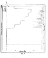
- the attenuating block 118 is substantially wedge-shaped and is formed of a stack of aluminum plates 120 of consistent thickness, resulting in a stepwise attenuation pattern (see Fig. 10 for a graphical representation of the stepwise attenuation pattern).
- the attenuating block 118 of the illustrated embodiment is coupled to the couch 82 and is moved into and out of the path of the radiation beam with movement of the couch 82 (i.e., the attenuating block 118 is moved into and out of the path of the x-ray source, which is the linac 26 in the illustrated embodiment),
- the attenuating block 118 can be coupled to a separate device used to move the block 118 into and out of the path of the radiation beam generated by the linac 26.
- the attenuating block 118 may be stationary.
- the attenuation block 118 can be used for measurement with a beam having any given energy, though the thicknesses of the aluminum plates 120 (or the overall thickness of the attenuating block 118) may need to be adjusted to compensate for the beam strength.
- the attenuating block 118 achieves similar attenuation results as the conventional use of the water tank.
- the results obtained by using the block 118 can be compared to the expected results from using the water tank attenuation.
- the use of aluminum as the material to form the attenuating block 118 has certain benefits. First, aluminum is denser than water such that less material is required to simulate a given depth of water. This reduces both the weight of the attenuator and the thickness of the required aluminum plates. Further, at the energy levels that are tested during the commissioning, service, and QA processes, the aluminum exhibits relatively similar properties to the water, making it easier to compare the attenuation results of the block 118 and the expected-water results.
- any number of materials can be used to create the block so long as the signature of the material is known.
- plastics or other metals can be used to create the block 118, though in many cases thicker plates of the other materials would be required to generate the same results as the aluminum plates.
- the aluminum plates of the illustrated embodiment are all of equal thicknesses, in other embodiments the plates themselves can be of varied thicknesses, depending on the desired results.
- Fig. 6 illustrates a screen shot 122 generated on a graphical user interface of the system 10 by the software that controls the twinning process.
- the user can input information regarding the control of various portions of the system 10, including the beam (at 126), the couch 82 (at 130), the MLC 62 (at 134), the gantry 18 (at 138), and the jaws 46 (at 142).
- the software collects data from the system 10 and generates outputs, such as the graphical representations illustrated in Figs. 8-10 .
- the software provides for efficient system tuning by integrating the control and measurement functions, and is essentially fully automated.
- the software includes fixed scripts that determine how to appropriately collect the data generated by the system 10.
- the software itself can determine how to appropriately change the inputs to generate the desired results.
- the software can have a feedback mechanism to take the data, remediate the data where necessary, and then re-measure the data without requiring further input from the user.
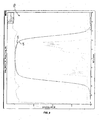
- Fig. 8 is an exemplary graphical output created by the software.
- the graph 146 represents the longitudinal profile (i.e., the IEC y-direction data) of the beam.
- the shape of the graph 146 is determined by the position of the jaws 46.
- the graph 146 includes a first data line 150 (shown in purple) generated from data received by the ion chamber 102 overlaid onto the gold standard data line 154 (shown in gray) for a twinned system 10.
- the first data line 150 is virtually identical to the gold standard data line 154, confirming that the system 10 is twinned to the gold standard in the y-direction.
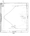
- FIG. 9 is a graph 158 representing the transverse profile data (i.e., the x-direction data) of the beam.
- a first data line 162 (in purple) is overlaid onto the gold standard data line 166 (in gray) to confirm the twinning in the x-direction.
- Both the longitudinal and transverse profile data are a function of the shape of the beam 30.
- Fig. 10 is a graphical output 170 representing the attenuation data of the step-wedge attenuation block 118.
- Fig. 11 illustrates an adjustment bracket 174 according to an embodiment of the invention.
- the adjustment bracket 174 includes a plurality of fasteners, shown as bolts 178, which allow for easy adjustment of the linac 26 on the gantry 18:
- bolts 178 which allow for easy adjustment of the linac 26 on the gantry 18:
- the linac 26 needs to be aligned, or "dialed-in", so to speak.
- the linac did not move naturally in the x-direction independently of motion in the y-direction, and vice versa. The natural motion was closer to diagonal in effect. Thus, it was difficult to accurately move the linac and any movement made had a compound effect, with an x-direction component and a y-direction component.
- the bracket 174 allows for independent movement of the linac 26 in the x and y-directions so that the linac 26 can be adjusted with precision and with ease.
- the arm 90 and thus the ion chamber 102, will rotate with the gantry 18.
- other measurements are possible, such as measurements of the changes in beam field shape, the measurement of any gantry sag, etc.
- the beam geometry can be validated using the arm 90 (e.g., the scanner 98) without using the attenuation block 118. If preferred, a separate movement apparatus can be utilized to move the block 118 into the path of the linac 26 at any beam angle. Other measurement functions, such as measuring energy output of the linac 26, can also be performed without the use of the block 118.
- the arm 90 can be used to gather calibration data in both the x and y-directions: This allows for more robust calibration of the detector, as the data could be used to determine how the detector signals vary with system wobble.
- the calibration would thus be a function of gantry angle, rotation, and stability.
- the arm 90 could be replaced with a detector or detector array operable to measure in two dimensions (e.g., measure the y-profile in addition to the x-profile).
- the attenuation block and ion chambers could be integrated into one unit.
- the arm 90 and/or block 118 can be used to get profiles for single leaves 66 of the MLC 62.
- the leaves could be static or moving and characterizing the output during leaf motion.
- the MLC could be the MLC 62 illustrated above, or could be a two-dimensional MLC having sliding leaves. We could also calibrate for all jaw thicknesses, altering the beam shape to get different field shapes in the y-direction.
- the arm 90 and/or block 118 can be used to get beam characteristics as a function of the position of the linac, or vice versa.
- the device could be used for linac tuning.
- the apparatus could also be used in an MLC tongue and groove test for MLC alignment.
- the arm 90 could be normalized out of the measurement, where appropriate.
Landscapes
- Health & Medical Sciences (AREA)
- Engineering & Computer Science (AREA)
- Biomedical Technology (AREA)
- Pathology (AREA)
- Nuclear Medicine, Radiotherapy & Molecular Imaging (AREA)
- Radiology & Medical Imaging (AREA)
- Life Sciences & Earth Sciences (AREA)
- Animal Behavior & Ethology (AREA)
- General Health & Medical Sciences (AREA)
- Public Health (AREA)
- Veterinary Medicine (AREA)
- Radiation-Therapy Devices (AREA)
Applications Claiming Priority (2)
| Application Number | Priority Date | Filing Date | Title |
|---|---|---|---|
| US82069006P | 2006-07-28 | 2006-07-28 | |
| EP07836301A EP2046450A4 (fr) | 2006-07-28 | 2007-07-27 | Procédé et appareil de calibrage d'un circuit de traitement de radiothérapie |
Related Parent Applications (1)
| Application Number | Title | Priority Date | Filing Date |
|---|---|---|---|
| EP07836301A Division EP2046450A4 (fr) | 2006-07-28 | 2007-07-27 | Procédé et appareil de calibrage d'un circuit de traitement de radiothérapie |
Publications (2)
| Publication Number | Publication Date |
|---|---|
| EP1967228A2 true EP1967228A2 (fr) | 2008-09-10 |
| EP1967228A3 EP1967228A3 (fr) | 2009-10-21 |
Family
ID=38982104
Family Applications (2)
| Application Number | Title | Priority Date | Filing Date |
|---|---|---|---|
| EP07836301A Withdrawn EP2046450A4 (fr) | 2006-07-28 | 2007-07-27 | Procédé et appareil de calibrage d'un circuit de traitement de radiothérapie |
| EP08005758A Withdrawn EP1967228A3 (fr) | 2006-07-28 | 2007-07-27 | Procédé et appareil d'étalonnage d'un système de traitement de thérapie à rayonnement |
Family Applications Before (1)
| Application Number | Title | Priority Date | Filing Date |
|---|---|---|---|
| EP07836301A Withdrawn EP2046450A4 (fr) | 2006-07-28 | 2007-07-27 | Procédé et appareil de calibrage d'un circuit de traitement de radiothérapie |
Country Status (8)
| Country | Link |
|---|---|
| US (1) | US7801269B2 (fr) |
| EP (2) | EP2046450A4 (fr) |
| JP (1) | JP2009544446A (fr) |
| KR (1) | KR20090046861A (fr) |
| CN (1) | CN101610811A (fr) |
| AU (1) | AU2007277082A1 (fr) |
| CA (1) | CA2659227A1 (fr) |
| WO (1) | WO2008013944A2 (fr) |
Cited By (1)
| Publication number | Priority date | Publication date | Assignee | Title |
|---|---|---|---|---|
| EP2457237B1 (fr) * | 2009-07-23 | 2019-12-11 | Sun Nuclear Corp. | Système de balayage à axes multiples pour la mesure de rayonnement à partir d'une source de rayonnement |
Families Citing this family (44)
| Publication number | Priority date | Publication date | Assignee | Title |
|---|---|---|---|---|
| EP3557956A1 (fr) | 2004-07-21 | 2019-10-23 | Mevion Medical Systems, Inc. | Générateur de forme d'onde de fréquence radio programmable pour un synchrocyclotron |
| ES2730108T3 (es) * | 2005-11-18 | 2019-11-08 | Mevion Medical Systems Inc | Radioterapia de partículas cargadas |
| US8581523B2 (en) | 2007-11-30 | 2013-11-12 | Mevion Medical Systems, Inc. | Interrupted particle source |
| US8933650B2 (en) | 2007-11-30 | 2015-01-13 | Mevion Medical Systems, Inc. | Matching a resonant frequency of a resonant cavity to a frequency of an input voltage |
| WO2009155700A1 (fr) * | 2008-06-24 | 2009-12-30 | Marco Carlone | Système de radiothérapie |
| US8632448B1 (en) | 2009-02-05 | 2014-01-21 | Loma Linda University Medical Center | Proton scattering analysis system |
| US8669533B2 (en) | 2009-10-01 | 2014-03-11 | Vladimir Bashkirov | Ion induced impact ionization detector and uses thereof |
| AU2011215659B2 (en) | 2010-02-12 | 2013-10-17 | Loma Linda University Medical Center | Systems and methodologies for proton computed tomography |
| WO2011106433A1 (fr) | 2010-02-24 | 2011-09-01 | Accuray Incorporated | Système de radiothérapie guidée par l'image comprenant un portique et méthodes d'administration de traitement associées |
| US9687200B2 (en) * | 2010-06-08 | 2017-06-27 | Accuray Incorporated | Radiation treatment delivery system with translatable ring gantry |
| US8536547B2 (en) | 2011-01-20 | 2013-09-17 | Accuray Incorporated | Ring gantry radiation treatment delivery system with dynamically controllable inward extension of treatment head |
| CA2829094A1 (fr) * | 2011-03-07 | 2012-11-29 | Loma Linda University Medical Center | Systemes, dispositifs et procedes relatifs a l'etalonnage d'un scanner de tomographie par emission de protons calculee par ordinateur |
| US8827555B2 (en) | 2011-06-13 | 2014-09-09 | Elekta Ab (Publ) | Method of calibrating a radiotherapy system |
| CN104813747B (zh) | 2012-09-28 | 2018-02-02 | 梅维昂医疗系统股份有限公司 | 使用磁场颤振聚焦粒子束 |
| US10254739B2 (en) | 2012-09-28 | 2019-04-09 | Mevion Medical Systems, Inc. | Coil positioning system |
| JP6121545B2 (ja) | 2012-09-28 | 2017-04-26 | メビオン・メディカル・システムズ・インコーポレーテッド | 粒子ビームのエネルギーの調整 |
| EP2900326B1 (fr) | 2012-09-28 | 2019-05-01 | Mevion Medical Systems, Inc. | Commande de thérapie par particules |
| TW201422278A (zh) | 2012-09-28 | 2014-06-16 | Mevion Medical Systems Inc | 粒子加速器之控制系統 |
| EP2901824B1 (fr) | 2012-09-28 | 2020-04-15 | Mevion Medical Systems, Inc. | Éléments d'homogénéisation de champ magnétique permettant d'ajuster la position de la bobine principale et procédé correspondant |
| EP2901823B1 (fr) | 2012-09-28 | 2021-12-08 | Mevion Medical Systems, Inc. | Contrôle de l'intensité d'un faisceau de particules |
| TW201422279A (zh) | 2012-09-28 | 2014-06-16 | Mevion Medical Systems Inc | 聚焦粒子束 |
| EP2901821B1 (fr) | 2012-09-28 | 2020-07-08 | Mevion Medical Systems, Inc. | Régénérateur de champ magnétique |
| EP2962309B1 (fr) | 2013-02-26 | 2022-02-16 | Accuray, Inc. | Collimateur multilame actionné par voie électromagnétique |
| US8791656B1 (en) | 2013-05-31 | 2014-07-29 | Mevion Medical Systems, Inc. | Active return system |
| US9730308B2 (en) | 2013-06-12 | 2017-08-08 | Mevion Medical Systems, Inc. | Particle accelerator that produces charged particles having variable energies |
| EP3049151B1 (fr) | 2013-09-27 | 2019-12-25 | Mevion Medical Systems, Inc. | Balayage par un faisceau de particules |
| US10675487B2 (en) | 2013-12-20 | 2020-06-09 | Mevion Medical Systems, Inc. | Energy degrader enabling high-speed energy switching |
| US9962560B2 (en) | 2013-12-20 | 2018-05-08 | Mevion Medical Systems, Inc. | Collimator and energy degrader |
| US9661736B2 (en) | 2014-02-20 | 2017-05-23 | Mevion Medical Systems, Inc. | Scanning system for a particle therapy system |
| US9844358B2 (en) | 2014-06-04 | 2017-12-19 | Varian Medical Systems, Inc. | Imaging-based self-adjusting radiation therapy systems, devices, and methods |
| CN106794358B (zh) | 2014-06-20 | 2019-09-13 | 华盛顿大学 | 一种用于验收测试和调试线性加速器的方法及系统 |
| US9950194B2 (en) | 2014-09-09 | 2018-04-24 | Mevion Medical Systems, Inc. | Patient positioning system |
| US10786689B2 (en) | 2015-11-10 | 2020-09-29 | Mevion Medical Systems, Inc. | Adaptive aperture |
| US10037863B2 (en) * | 2016-05-27 | 2018-07-31 | Mark R. Amato | Continuous ion beam kinetic energy dissipater apparatus and method of use thereof |
| US20170348547A1 (en) * | 2016-05-27 | 2017-12-07 | W. Davis Lee | Ion beam kinetic energy dissipater apparatus and method of use thereof |
| US10925147B2 (en) | 2016-07-08 | 2021-02-16 | Mevion Medical Systems, Inc. | Treatment planning |
| CN106443749B (zh) * | 2016-08-31 | 2019-04-16 | 北京康科达科技有限公司 | 三维自动扫描水箱 |
| US11103730B2 (en) | 2017-02-23 | 2021-08-31 | Mevion Medical Systems, Inc. | Automated treatment in particle therapy |
| US10335613B2 (en) | 2017-03-28 | 2019-07-02 | Varian Medical Systems International Ag | Systems, methods, and devices for commissioning and quality assurance data validation of radiation therapy systems |
| JP6940676B2 (ja) | 2017-06-30 | 2021-09-29 | メビオン・メディカル・システムズ・インコーポレーテッド | リニアモーターを使用して制御される構成可能コリメータ |
| TWI816951B (zh) * | 2018-12-11 | 2023-10-01 | 日商J Beam股份有限公司 | 中子診斷裝置 |
| EP3934751B1 (fr) | 2019-03-08 | 2024-07-17 | Mevion Medical Systems, Inc. | Collimateur et dégradeur d'énergie pour système de thérapie par particules |
| GB2590454B (en) * | 2019-12-18 | 2022-01-05 | Elekta ltd | A method of characterising physical properties of an attenuating element in a radiotherapy device |
| EP3858436A1 (fr) * | 2020-01-28 | 2021-08-04 | Panacea Medical Technologies Pvt. Ltd | Système automatique pour la fourniture d'une assurance qualité de radiothérapie intégrant une analyse de champ de rayonnement |
Citations (4)
| Publication number | Priority date | Publication date | Assignee | Title |
|---|---|---|---|---|
| US4988866A (en) * | 1987-07-21 | 1991-01-29 | Westerlund Kjell B | Measuring device for checking radiation fields from treatment machines for radiotherapy |
| US5627367A (en) * | 1995-10-10 | 1997-05-06 | Sofield Science Services, Inc. | Radiation beam calibrater |
| WO2000007037A1 (fr) * | 1998-07-31 | 2000-02-10 | Daniel Navarro | Dispositif de balayage de rayonnement dynamique |
| WO2002024277A1 (fr) | 2000-09-22 | 2002-03-28 | Radiological Imaging Technology, Inc. | Etalonnage automatise pour dosimetrie des rayonnements au moyen de detecteurs et de faisceaux fixes ou en deplacement |
Family Cites Families (31)
| Publication number | Priority date | Publication date | Assignee | Title |
|---|---|---|---|---|
| US5008907A (en) | 1989-05-31 | 1991-04-16 | The Regents Of The University Of California | Therapy x-ray scanner |
| AU646068B2 (en) | 1990-07-02 | 1994-02-03 | Varian Medical Systems, Inc. | Computed tomography apparatus using image intensifier detector |
| US5117445A (en) | 1990-07-02 | 1992-05-26 | Varian Associates, Inc. | Electronically enhanced x-ray detector apparatus |
| US5138647A (en) * | 1990-08-03 | 1992-08-11 | Siemens Medical Laboratories, Inc. | Portal imaging device |
| US5351280A (en) * | 1992-03-19 | 1994-09-27 | Wisconsin Alumni Research Foundation | Multi-leaf radiation attenuator for radiation therapy |
| US5748703A (en) | 1994-03-22 | 1998-05-05 | Cosman; Eric R. | Dynamic collimator for a linear accelerator |
| US6345114B1 (en) * | 1995-06-14 | 2002-02-05 | Wisconsin Alumni Research Foundation | Method and apparatus for calibration of radiation therapy equipment and verification of radiation treatment |
| JP3203211B2 (ja) * | 1997-08-11 | 2001-08-27 | 住友重機械工業株式会社 | 水ファントム型線量分布測定装置及び放射線治療装置 |
| US6636622B2 (en) | 1997-10-15 | 2003-10-21 | Wisconsin Alumni Research Foundation | Method and apparatus for calibration of radiation therapy equipment and verification of radiation treatment |
| US6134292A (en) | 1998-07-13 | 2000-10-17 | General Electric Company | Methods and apparatus for reducing z-axis non-uniformity artifacts |
| JP3775992B2 (ja) * | 1998-08-06 | 2006-05-17 | ウイスコンシン アラムナイ リサーチ フオンデーシヨン | 放射線治療検査システム |
| US6454460B1 (en) | 1998-09-08 | 2002-09-24 | Naganathasastrigal Ramanathan | System and method for evaluating and calibrating a radiation generator |
| US6260999B1 (en) | 1999-07-26 | 2001-07-17 | Siemens Medical Systems, Inc. | Isocenter localization using electronic portal imaging |
| US6466644B1 (en) | 1999-10-06 | 2002-10-15 | Siemens Medical Solutions Usa, Inc. | Method and system for verification of different types of beam limiting devices in a linear accelerator utilized for radiotherapy |
| US6528803B1 (en) | 2000-01-21 | 2003-03-04 | Radiological Imaging Technology, Inc. | Automated calibration adjustment for film dosimetry |
| US6853702B2 (en) | 2000-12-15 | 2005-02-08 | Wendel Dean Renner | Radiation therapy dosimetry quality control process |
| US6810107B2 (en) * | 2001-11-02 | 2004-10-26 | Siemens Medical Solutions Usa, Inc. | System and method for measuring beam quality and dosimetry using electronic portal imaging |
| US6888919B2 (en) | 2001-11-02 | 2005-05-03 | Varian Medical Systems, Inc. | Radiotherapy apparatus equipped with an articulable gantry for positioning an imaging unit |
| US6760402B2 (en) | 2002-08-01 | 2004-07-06 | Siemens Medical Solutions Usa, Inc. | Verification of mlc leaf position and of radiation and light field congruence |
| WO2004103457A2 (fr) * | 2003-05-14 | 2004-12-02 | Washington University In St.Louis | Radiotherapie par micro-faisceaux amelioree et procede d'irradiation de systemes biologiques au moyen de micro-faisceaux |
| WO2004105574A2 (fr) * | 2003-05-21 | 2004-12-09 | William Beaumont Hospital | Radiotherapie guidee par images |
| US6904125B2 (en) | 2003-07-14 | 2005-06-07 | Cancer Care Ontario | Phantom for evaluating nondosimetric functions in a multi-leaf collimated radiation treatment planning system |
| US6937751B2 (en) | 2003-07-30 | 2005-08-30 | Radiological Imaging Technology, Inc. | System and method for aligning images |
| US6934358B2 (en) | 2003-07-31 | 2005-08-23 | Radiological Imaging Technology, Inc. | Radiographic imaging system and method |
| US20070197908A1 (en) | 2003-10-29 | 2007-08-23 | Ruchala Kenneth J | System and method for calibrating and positioning a radiation therapy treatment table |
| US7130372B2 (en) | 2004-06-08 | 2006-10-31 | Siemens Medical Solutions Usa, Inc. | Linear accelerator with X-ray imaging elements mounted on curved support |
| US7327902B2 (en) | 2004-12-10 | 2008-02-05 | Radiological Imaging Technology, Inc. | Optimizing image alignment |
| US7024026B1 (en) | 2005-01-20 | 2006-04-04 | Radiological Imaging Technology, Inc. | Relative calibration for dosimetric devices |
| US7233688B2 (en) * | 2005-01-20 | 2007-06-19 | Radiological Imaging Technology Inc. | Relative and absolute calibration for dosimetric devices |
| US7252434B2 (en) | 2005-03-16 | 2007-08-07 | Wisconsin Alumni Research Foundation | Radiation therapy machine calibration apparatus providing multiple angle measurements |
| US7590218B2 (en) | 2005-03-23 | 2009-09-15 | Best Medical International, Inc. | System for monitoring the geometry of a radiation treatment apparatus, trackable assembly, program product, and related methods |
-
2007
- 2007-07-27 EP EP07836301A patent/EP2046450A4/fr not_active Withdrawn
- 2007-07-27 AU AU2007277082A patent/AU2007277082A1/en not_active Abandoned
- 2007-07-27 WO PCT/US2007/016920 patent/WO2008013944A2/fr not_active Ceased
- 2007-07-27 EP EP08005758A patent/EP1967228A3/fr not_active Withdrawn
- 2007-07-27 JP JP2009522808A patent/JP2009544446A/ja active Pending
- 2007-07-27 KR KR1020097003808A patent/KR20090046861A/ko not_active Withdrawn
- 2007-07-27 CA CA002659227A patent/CA2659227A1/fr not_active Abandoned
- 2007-07-27 US US11/881,542 patent/US7801269B2/en active Active
- 2007-07-27 CN CNA2007800286929A patent/CN101610811A/zh active Pending
Patent Citations (4)
| Publication number | Priority date | Publication date | Assignee | Title |
|---|---|---|---|---|
| US4988866A (en) * | 1987-07-21 | 1991-01-29 | Westerlund Kjell B | Measuring device for checking radiation fields from treatment machines for radiotherapy |
| US5627367A (en) * | 1995-10-10 | 1997-05-06 | Sofield Science Services, Inc. | Radiation beam calibrater |
| WO2000007037A1 (fr) * | 1998-07-31 | 2000-02-10 | Daniel Navarro | Dispositif de balayage de rayonnement dynamique |
| WO2002024277A1 (fr) | 2000-09-22 | 2002-03-28 | Radiological Imaging Technology, Inc. | Etalonnage automatise pour dosimetrie des rayonnements au moyen de detecteurs et de faisceaux fixes ou en deplacement |
Cited By (1)
| Publication number | Priority date | Publication date | Assignee | Title |
|---|---|---|---|---|
| EP2457237B1 (fr) * | 2009-07-23 | 2019-12-11 | Sun Nuclear Corp. | Système de balayage à axes multiples pour la mesure de rayonnement à partir d'une source de rayonnement |
Also Published As
| Publication number | Publication date |
|---|---|
| US7801269B2 (en) | 2010-09-21 |
| EP2046450A2 (fr) | 2009-04-15 |
| US20080083871A1 (en) | 2008-04-10 |
| JP2009544446A (ja) | 2009-12-17 |
| EP2046450A4 (fr) | 2009-10-21 |
| CN101610811A (zh) | 2009-12-23 |
| KR20090046861A (ko) | 2009-05-11 |
| AU2007277082A1 (en) | 2008-01-31 |
| WO2008013944A3 (fr) | 2008-04-03 |
| EP1967228A3 (fr) | 2009-10-21 |
| WO2008013944A2 (fr) | 2008-01-31 |
| CA2659227A1 (fr) | 2008-01-31 |
Similar Documents
| Publication | Publication Date | Title |
|---|---|---|
| US7801269B2 (en) | Method and apparatus for calibrating a radiation therapy treatment system | |
| JP7564098B2 (ja) | 画像誘導放射線治療装置内に統合されるヘリカルファンビームコンピュータ断層撮影 | |
| US8122542B2 (en) | Patient support device | |
| US7564945B2 (en) | System including computed tomography device for image guided treatment | |
| CN101224324B (zh) | 带电粒子线治疗装置 | |
| CN1622843B (zh) | 用于执行和验证治疗的装置以及所属的控制器计算机 | |
| EP2321009B1 (fr) | Appareil de radiothérapie | |
| US10500420B2 (en) | Small beam area, mid-voltage radiotherapy system with reduced skin dose, reduced scatter around the treatment volume, and improved overall accuracy | |
| US20080170663A1 (en) | Radiation irradiation method and radiotherapy apparatus controller | |
| US7346144B2 (en) | In vivo planning and treatment of cancer therapy | |
| CN101309726A (zh) | 用于调制放射束的方法和设备 | |
| Balog et al. | Benchmarking beam alignment for a clinical helical tomotherapy device | |
| CN104302357A (zh) | 粒子束远程多向照射装置 | |
| US6782073B2 (en) | Planning system for convergent radiation treatment | |
| WO2013127005A1 (fr) | Imagerie par rayons x à dose réduite | |
| EP0817208A1 (fr) | Dispositif et procédé d'ajustement des radiations dans un dispositif les émettant | |
| US11065474B2 (en) | Patient alignment method and system using light field and light reflector during radiation therapy | |
| Masella et al. | Initial characterization of a novel dual-robot orthovoltage radiotherapy system | |
| US20140169519A1 (en) | Cone-beam CT Scanning | |
| EP4400161B1 (fr) | Système d'assurance qualité pour radiothérapie par particules | |
| Faddegon | Monte Carlo Simulations for Treatment Device Design | |
| TING | DOSIMETRIC QUALITY ASSURANCE | |
| Jäkel et al. | Treatment planning and dosimetric requirements for prescribing and reporting ion beam therapy: The current Heidelberg-Darmstadt approach | |
| HK1122753A (en) | Method and apparatus for modulating a radiation beam |
Legal Events
| Date | Code | Title | Description |
|---|---|---|---|
| PUAI | Public reference made under article 153(3) epc to a published international application that has entered the european phase |
Free format text: ORIGINAL CODE: 0009012 |
|
| 17P | Request for examination filed |
Effective date: 20080327 |
|
| AK | Designated contracting states |
Kind code of ref document: A2 Designated state(s): AT BE BG CH CY CZ DE DK EE ES FI FR GB GR HU IE IS IT LI LT LU LV MC MT NL PL PT RO SE SI SK TR |
|
| AX | Request for extension of the european patent |
Extension state: AL BA HR MK RS |
|
| RIN1 | Information on inventor provided before grant (corrected) |
Inventor name: CRAVENS, ROBERT L. Inventor name: HENDERSON, DOUGLAS Inventor name: DE SOUZA, CLEBER Inventor name: RECKWERDT, PAUL J. Inventor name: COX, ANDREA Inventor name: LUCAS, DANIEL Inventor name: OLIVERA, GUSTAVO H. Inventor name: RUCHALA, KENNETH J. |
|
| PUAL | Search report despatched |
Free format text: ORIGINAL CODE: 0009013 |
|
| AK | Designated contracting states |
Kind code of ref document: A3 Designated state(s): AT BE BG CH CY CZ DE DK EE ES FI FR GB GR HU IE IS IT LI LT LU LV MC MT NL PL PT RO SE SI SK TR |
|
| AX | Request for extension of the european patent |
Extension state: AL BA HR MK RS |
|
| 17Q | First examination report despatched |
Effective date: 20100518 |
|
| AKX | Designation fees paid |
Designated state(s): AT BE BG CH CY CZ DE DK EE ES FI FR GB GR HU IE IS IT LI LT LU LV MC MT NL PL PT RO SE SI SK TR |
|
| STAA | Information on the status of an ep patent application or granted ep patent |
Free format text: STATUS: THE APPLICATION IS DEEMED TO BE WITHDRAWN |
|
| 18D | Application deemed to be withdrawn |
Effective date: 20121002 |