EP1967284A2 - Procédé et dispositif de renforcement de rayonnement UV de revêtements de substrat - Google Patents
Procédé et dispositif de renforcement de rayonnement UV de revêtements de substrat Download PDFInfo
- Publication number
- EP1967284A2 EP1967284A2 EP08152162A EP08152162A EP1967284A2 EP 1967284 A2 EP1967284 A2 EP 1967284A2 EP 08152162 A EP08152162 A EP 08152162A EP 08152162 A EP08152162 A EP 08152162A EP 1967284 A2 EP1967284 A2 EP 1967284A2
- Authority
- EP
- European Patent Office
- Prior art keywords
- inert gas
- coating
- irradiation
- substrate
- supplied
- Prior art date
- Legal status (The legal status is an assumption and is not a legal conclusion. Google has not performed a legal analysis and makes no representation as to the accuracy of the status listed.)
- Withdrawn
Links
Images


Classifications
-
- B—PERFORMING OPERATIONS; TRANSPORTING
- B05—SPRAYING OR ATOMISING IN GENERAL; APPLYING FLUENT MATERIALS TO SURFACES, IN GENERAL
- B05D—PROCESSES FOR APPLYING FLUENT MATERIALS TO SURFACES, IN GENERAL
- B05D3/00—Pretreatment of surfaces to which liquids or other fluent materials are to be applied; After-treatment of applied coatings, e.g. intermediate treating of an applied coating preparatory to subsequent applications of liquids or other fluent materials
- B05D3/06—Pretreatment of surfaces to which liquids or other fluent materials are to be applied; After-treatment of applied coatings, e.g. intermediate treating of an applied coating preparatory to subsequent applications of liquids or other fluent materials by exposure to radiation
- B05D3/061—Pretreatment of surfaces to which liquids or other fluent materials are to be applied; After-treatment of applied coatings, e.g. intermediate treating of an applied coating preparatory to subsequent applications of liquids or other fluent materials by exposure to radiation using U.V.
- B05D3/065—After-treatment
- B05D3/066—After-treatment involving also the use of a gas
-
- B—PERFORMING OPERATIONS; TRANSPORTING
- B41—PRINTING; LINING MACHINES; TYPEWRITERS; STAMPS
- B41F—PRINTING MACHINES OR PRESSES
- B41F23/00—Devices for treating the surfaces of sheets, webs, or other articles in connection with printing
- B41F23/04—Devices for treating the surfaces of sheets, webs, or other articles in connection with printing by heat drying, by cooling, by applying powders
- B41F23/0403—Drying webs
- B41F23/0406—Drying webs by radiation
- B41F23/0409—Ultraviolet dryers
-
- B—PERFORMING OPERATIONS; TRANSPORTING
- B41—PRINTING; LINING MACHINES; TYPEWRITERS; STAMPS
- B41F—PRINTING MACHINES OR PRESSES
- B41F23/00—Devices for treating the surfaces of sheets, webs, or other articles in connection with printing
- B41F23/04—Devices for treating the surfaces of sheets, webs, or other articles in connection with printing by heat drying, by cooling, by applying powders
- B41F23/044—Drying sheets, e.g. between two printing stations
- B41F23/0443—Drying sheets, e.g. between two printing stations after printing
-
- C—CHEMISTRY; METALLURGY
- C09—DYES; PAINTS; POLISHES; NATURAL RESINS; ADHESIVES; COMPOSITIONS NOT OTHERWISE PROVIDED FOR; APPLICATIONS OF MATERIALS NOT OTHERWISE PROVIDED FOR
- C09D—COATING COMPOSITIONS, e.g. PAINTS, VARNISHES OR LACQUERS; FILLING PASTES; CHEMICAL PAINT OR INK REMOVERS; INKS; CORRECTING FLUIDS; WOODSTAINS; PASTES OR SOLIDS FOR COLOURING OR PRINTING; USE OF MATERIALS THEREFOR
- C09D11/00—Inks
- C09D11/02—Printing inks
- C09D11/10—Printing inks based on artificial resins
- C09D11/101—Inks specially adapted for printing processes involving curing by wave energy or particle radiation, e.g. with UV-curing following the printing
-
- F—MECHANICAL ENGINEERING; LIGHTING; HEATING; WEAPONS; BLASTING
- F26—DRYING
- F26B—DRYING SOLID MATERIALS OR OBJECTS BY REMOVING LIQUID THEREFROM
- F26B21/00—Arrangements for supplying or controlling air or other gases for drying solid materials or objects
- F26B21/40—Arrangements for supplying or controlling air or other gases for drying solid materials or objects using gases other than air
-
- F—MECHANICAL ENGINEERING; LIGHTING; HEATING; WEAPONS; BLASTING
- F26—DRYING
- F26B—DRYING SOLID MATERIALS OR OBJECTS BY REMOVING LIQUID THEREFROM
- F26B3/00—Drying solid materials or objects by processes involving the application of heat
- F26B3/28—Drying solid materials or objects by processes involving the application of heat by radiation, e.g. from the sun
-
- B—PERFORMING OPERATIONS; TRANSPORTING
- B05—SPRAYING OR ATOMISING IN GENERAL; APPLYING FLUENT MATERIALS TO SURFACES, IN GENERAL
- B05D—PROCESSES FOR APPLYING FLUENT MATERIALS TO SURFACES, IN GENERAL
- B05D2252/00—Sheets
- B05D2252/04—Sheets of definite length in a continuous process
-
- B—PERFORMING OPERATIONS; TRANSPORTING
- B05—SPRAYING OR ATOMISING IN GENERAL; APPLYING FLUENT MATERIALS TO SURFACES, IN GENERAL
- B05D—PROCESSES FOR APPLYING FLUENT MATERIALS TO SURFACES, IN GENERAL
- B05D3/00—Pretreatment of surfaces to which liquids or other fluent materials are to be applied; After-treatment of applied coatings, e.g. intermediate treating of an applied coating preparatory to subsequent applications of liquids or other fluent materials
- B05D3/04—Pretreatment of surfaces to which liquids or other fluent materials are to be applied; After-treatment of applied coatings, e.g. intermediate treating of an applied coating preparatory to subsequent applications of liquids or other fluent materials by exposure to gases
- B05D3/0466—Pretreatment of surfaces to which liquids or other fluent materials are to be applied; After-treatment of applied coatings, e.g. intermediate treating of an applied coating preparatory to subsequent applications of liquids or other fluent materials by exposure to gases the gas being a non-reacting gas
-
- B—PERFORMING OPERATIONS; TRANSPORTING
- B05—SPRAYING OR ATOMISING IN GENERAL; APPLYING FLUENT MATERIALS TO SURFACES, IN GENERAL
- B05D—PROCESSES FOR APPLYING FLUENT MATERIALS TO SURFACES, IN GENERAL
- B05D3/00—Pretreatment of surfaces to which liquids or other fluent materials are to be applied; After-treatment of applied coatings, e.g. intermediate treating of an applied coating preparatory to subsequent applications of liquids or other fluent materials
- B05D3/06—Pretreatment of surfaces to which liquids or other fluent materials are to be applied; After-treatment of applied coatings, e.g. intermediate treating of an applied coating preparatory to subsequent applications of liquids or other fluent materials by exposure to radiation
- B05D3/061—Pretreatment of surfaces to which liquids or other fluent materials are to be applied; After-treatment of applied coatings, e.g. intermediate treating of an applied coating preparatory to subsequent applications of liquids or other fluent materials by exposure to radiation using U.V.
- B05D3/065—After-treatment
- B05D3/067—Curing or cross-linking the coating
-
- B—PERFORMING OPERATIONS; TRANSPORTING
- B29—WORKING OF PLASTICS; WORKING OF SUBSTANCES IN A PLASTIC STATE IN GENERAL
- B29C—SHAPING OR JOINING OF PLASTICS; SHAPING OF MATERIAL IN A PLASTIC STATE, NOT OTHERWISE PROVIDED FOR; AFTER-TREATMENT OF THE SHAPED PRODUCTS, e.g. REPAIRING
- B29C35/00—Heating, cooling or curing, e.g. crosslinking or vulcanising; Apparatus therefor
- B29C35/02—Heating or curing, e.g. crosslinking or vulcanizing during moulding, e.g. in a mould
- B29C35/08—Heating or curing, e.g. crosslinking or vulcanizing during moulding, e.g. in a mould by wave energy or particle radiation
- B29C35/0805—Heating or curing, e.g. crosslinking or vulcanizing during moulding, e.g. in a mould by wave energy or particle radiation using electromagnetic radiation
- B29C2035/0827—Heating or curing, e.g. crosslinking or vulcanizing during moulding, e.g. in a mould by wave energy or particle radiation using electromagnetic radiation using UV radiation
-
- B—PERFORMING OPERATIONS; TRANSPORTING
- B29—WORKING OF PLASTICS; WORKING OF SUBSTANCES IN A PLASTIC STATE IN GENERAL
- B29C—SHAPING OR JOINING OF PLASTICS; SHAPING OF MATERIAL IN A PLASTIC STATE, NOT OTHERWISE PROVIDED FOR; AFTER-TREATMENT OF THE SHAPED PRODUCTS, e.g. REPAIRING
- B29C2791/00—Shaping characteristics in general
- B29C2791/004—Shaping under special conditions
- B29C2791/005—Using a particular environment, e.g. sterile fluids other than air
Definitions
- the invention relates to a method and a device for radiation curing of a coating of a substrate with UV light according to the preamble of claims 1 and 19, respectively.
- Processes and devices of the type mentioned above are mainly used for curing of solvent-free coating systems, such as paints or varnishes, on substrates by crosslinking contained in the coating systems monomers and / or oligomers by the irradiation with UV light and as a result Conversion into solid polymers provides for a cure of the coating.
- solvent-free coating systems such as paints or varnishes
- the coated substrates may be coated three-dimensional objects, such as mobile phone housing shells, fittings and other decorative elements of furniture or furnishings, pump housings and automotive trim components, lipstick housing components, profile bars or tubes used to cure the coating Radiation field of a equipped with a UV lamp UV exposure device are moved through, such as in the EP 1 169 611 B1 the applicant discloses.
- radiation curing of coatings is also used to treat flat web or sheet substrates, such as substrates that are transported through the radiation field from one or more UV emitters after being printed in a web or ogen offset printing press To harden in the printing press on the substrate applied inks or paints.
- the UV emitters used usually consist of a mercury Nlitteldruckgasentladungslampe whose emission spectrum can be adjusted by appropriate dopants to the chemical composition of the respective coating.
- UV light curing is a free radical polymerization, i. a reaction whose action is affected by the action of atmospheric oxygen, since oxygen biradicals disrupt chain formation, undesirably resulting in a tacky or weakly crosslinked surface layer. Therefore, it is already known to carry out the irradiation with UV light in an oxygen-reduced atmosphere.
- the present invention seeks to improve a method and an apparatus of the type mentioned in that the amount of inert gas required for radiation curing can be reduced without affecting the quality or surface finish of the coating.
- a preferred embodiment of the invention provides that the inert gas is blown directly onto the UV-irradiated coating.
- the inert gas supply is preferably taken up only after the beginning of the irradiation with the UV light at a given irradiation site and / or interrupted again before the end of the irradiation with the UV light, since this completely sufficient due to the experimental results for the inerting / oxygen reduction is.
- the inert gas in the vicinity of the coating for at least 10% and preferably at least 20% of the irradiation time to ensure the effect on the coating.
- the amount of inert gas supplied and / or the duration of the inert gas supply can be adjusted according to requirements, for example, depending on the size of the substrate surface provided with the coating and / or the type of coating.
- a pulsed or intermittent supply may be advantageous in the InertgasstShute are interrupted by pauses.
- the inert gas can be supplied in the form of a laminar or turbulent flow in the vicinity of the coating.
- the inert gas is supplied at a given irradiation site within an irradiation unit present there only for a short time or only at the point at which the inerting is particularly effective with low gas consumption.
- the coated substrate it is possible for the coated substrate to be exposed to inert gas in the passage through a radiation field of a stationary UV radiator, the inert gas being supplied only in a partial region of the radiation field.
- either three-dimensional bodies or two-dimensional substrates these are expediently moved successively through a radiation field of at least one UV emitter.
- the inert gas is always supplied to the irradiation site when just one of the substrates is in the radiation field, while the inert gas is interrupted or stopped when there is no substrate with a coating to be cured in the radiation field.
- the supply of the inert gas becomes resumed, however, is expediently terminated before the exit of the substrate from the radiation field again.
- the substrates provided with the coating can be successively moved through the radiation fields of two or more UV lamps, wherein the inert gas is supplied only in the radiation field of one of the UV lamps (preferably the last emitter for the final curing) in the vicinity of the coating , while in the radiation field of the or the other UV emitters no supply of inert gas.
- the substrate In order to supply the inert gas in the vicinity of the coating, the substrate can be moved through a curtain of inert gas, which preferably extends within the radiation field transverse to the path of movement of the substrate or parallel to the longitudinal direction of the UV lamp.
- a curtain of inert gas which preferably extends within the radiation field transverse to the path of movement of the substrate or parallel to the longitudinal direction of the UV lamp.
- this is expediently fed through at least one nozzle, which is preferably arranged on the same side of the substrate movement path as the UV radiator and advantageously outside the radiation field of the UV radiator to shield no UV light.
- inert gas is supplied only after the last printing unit during the radiation hardening, while behind the other printing units the irradiation takes place without a supply of inert gas.
- the last-mentioned measures provide for UV irradiation behind the printing units, where no inert gas is supplied, for superficial gelation of the respective printing ink on the printed pixels, while the complete curing of the printing ink or varnish due to the UV irradiation taking place under inert gas supply the last printing unit or behind the coating unit.
- the method according to the invention can also be used in all other common printing and lacquer application methods, such as in flexographic printing, screen printing, ink jet printing and also in immersion, spray and vacuum coating processes.
- a device for radiation curing of a coating of a substrate has at least one UV radiator for irradiating the coating with UV light and a gas supply device for supplying an inert gas in the vicinity of the coating within the irradiation field and is characterized in that the gas supply means a control unit for Interruption of the inert gas supply during part of the duration of the UV irradiation of the substrate comprises.
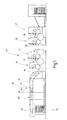
- FIGS. 1 to 3 illustrated devices 1 are used for radiation curing of a curable by irradiation with UV light coating on three-dimensional objects 2, such as housing shells of mobile phones, fittings and other decorative elements of furniture or furnishings or trim parts of motor vehicles, in Fig. 1 and 2 are shown only schematically as a rectangle or cube.
- the devices 1 comprise an irradiation chamber 6 as irradiation site with an inlet opening 10 closable by a slide 8 and an outlet opening 14 closable by a slide 12, a straight line through the inlet opening 10, the interior of the irradiation chamber 6 and the outlet opening 14
- Transport means 16 for transporting the coated objects 2 a UV aggregate 18 arranged at a distance above the transport means 16 in the irradiation chamber 6, a nitrogen supply nozzle 20 also above the transport means 16 and at a small distance above the objects 2 transported by the transport means 16 the irradiation chamber 6 is arranged and connected to a nitrogen source 26 via a valve 24 controlled by a valve control 22, and a process control unit 28 for controlling the irradiation of the objects 2 with UV light and for controlling the supply of nitrogen in the irradiation chamber 6.
- the irradiation chamber 6 serves as light protection for the operating personnel of the devices 1 as well as for the continuous extraction of possibly accumulating ozone.
- the inlet opening 10 and the outlet opening 14 are opposite on opposite sides of the irradiation chamber 6, each extending from the transport means 16 upwards and are normally closed by the slide 8 and 12 respectively. During the approach of one of the objects 2 to the inlet and outlet openings 10 and 14, the slides 8 and 12 are briefly moved sufficiently far up to pass the objects 2 through the openings 10, 14.
- the movement of the slides 8, 12 is controlled by the process control unit 28 in response to the signals from sensors 30, 32, for example non-contact optical sensors, which are respectively arranged in the transport direction T in front of the inlet or outlet opening 10, 14 above the transport means 16 and send a signal to the process control unit 28 as an object 2 passes.
- sensors 30, 32 for example non-contact optical sensors, which are respectively arranged in the transport direction T in front of the inlet or outlet opening 10, 14 above the transport means 16 and send a signal to the process control unit 28 as an object 2 passes.
- the UV unit 18 contains a UV radiator 34 in the form of a mercury medium-pressure gas discharge lamp, which is aligned transversely to the transport direction T of the objects 2, and two above the UV radiator 34 arranged reflectors 36, so that emitted by the UV lamp UV Light is emitted downwards in the direction of the transport means 16 and on moving objects 2 passing through the UV unit 18 through the transport means 16 through a truncated pyramidal radiation field 38 of the UV emitter 34.
- they can be rotated on their path of movement through the irradiation chamber 6 with respect to the transport means 16, as indicated by the arrows A in FIG Fig. 2 and 3 shown schematically.
- the UV aggregate 18 may be an irradiation device through which nitrogen from the nitrogen source 26 is circulated as a cooling gas, similar to the one in FIG EP 1 169 611 B1 to which reference is made for further details.
- a UV aggregate 18 with pure air cooling can be used, in which the UV radiator 34 is separated from the irradiation chamber 6 by a quartz disk and works with negative pressure or overpressure cooling of the radiator 34 and the reflectors 36.
- the use of a patch on the irradiation chamber 6 UV unit 18 without gas cooling of the lamp chamber is possible, as for example from the DE 10 2005 046 233 A1 is known.
- the emerging from the gas outlet opening 40 nitrogen above the transport means 16 forms a kind of curtain, which extends down through the radiation field 38 to the transport means 16 so that it succeeds without complete filling of the irradiation chamber 6 with nitrogen, the coating to be cured of the objects 2 within the radiation field 38 for a short time with the supplied into the irradiation chamber 6 To bring nitrogen into contact.
- the period of time during which exposure of the nitrogen to the coating of the objects 2 is required is only a fraction of the irradiation time, but preferably an exposure time of at least 10% and preferably about 20% of the irradiation time is desired.
- the valve 24 between the nitrogen source 24 and the nitrogen supply nozzle 20 is driven in response to a signal from the sensor 30 and depending on the transport speed of the transport means 16 so that only nitrogen from the nozzle 20 is fed into the irradiation chamber 6 when one of the objects 6 has entered the radiation field 38 so far that the nitrogen exiting from the nozzle 20 impinges on the coated with the UV light coated surface of the object 2 and there to curing coating briefly flows around or flows.
- the valve 24 is immediately closed again after the object 2 has leaked out of the radiation field 38 or completely passed through the nitrogen curtain produced by the nozzle 20.
- the time for closing the valve 24 may be calculated in dependence on the transport speed of the transport means 16 and the time of the response of the sensor 30. Alternatively, however, a signal originating from the sensor 32 or an additional sensor (not shown) may also be used.
- the amount and duration of the nitrogen supply are adjustable by varying the degree of opening and the opening duration of the valve 24 in the valve control unit 22 to accommodate objects 2 having different sized surfaces or coatings of different composition.
- pulsed nitrogen supply may be advantageous, ie, intermittent short-term opening and closing of the valve 24 between the nitrogen source 26 and the nozzle 20 during the duration of the passage of an object 2 through the radiation field 38 or through the nitrogen jet blown from the nozzle 20 onto the object 2.
- Fig. 3 shown device differs from the device in the Figures 1 and 2 in that an additional nitrogen supply nozzle 42 is provided, which extends like the nozzle 20 outside the radiation field 38 of the UV aggregate 18 parallel to the longitudinal axis of the UV radiator 34 over the transport path of the objects 2, but in the direction of movement of the objects 2 in front of the radiation field 38 is arranged and has an obliquely downward in the direction of movement of the objects 2 facing outlet opening 44.
- the two nitrogen supply nozzles 20, 42 can be supplied from the valve controller 22 or the process control unit 28 via separate valves (in FIG Fig. 3 not shown) are connected to the nitrogen source 26, so that either at the entrance or at the exit of an object 2 from the radiation field 38, nitrogen can be briefly blown onto the surfaces of the object 2 provided with the coating.
- Fig. 4 shows by four curves I to IV the depth-resolved degree of conversion of unsaturated double bonds in a coating of three samples at a radiation time of 5 seconds duration and a nitrogen exposure time of 1 second duration at the beginning (curve I), in the middle (curve II) and at the end (Curve III) of the irradiation time, as well as a reference sample (Curve IV) without any supply of nitrogen during UV irradiation.
- the reference sample has a reduced degree of conversion due to inhibition by diffused oxygen in the air to a depth of about 30 .mu.m, whereas this is not or only very slightly the case with the other three samples.
- the best results in the degree of conversion are obtained when the nitrogen at the beginning (curve I) or in the middle (curve II) is supplied to the irradiation period for a short time.
- Fig. 5 shows a sheet-fed offset printing machine 44, in which a sheet-like substrate 46 as a substrate in a plurality of printing units 48, 50, 52 (only partially shown) printed with different colored UV-curing inks and coated in a downstream coating unit 54 with a transparent UV-curing lacquer , Behind each printing unit 48, 50, 52 is a UV aggregate 56, which has a similar construction as in Fig. 2 and 3 shown UV unit 18 has and its UV radiator extends transversely to the transport direction of the sheet on the transport path. With the aid of the UV aggregates 56, the previously printed surface of the sheets can be irradiated with UV light in order to ensure superficial setting of the respective printing ink on the printed pixels. Irradiation by the UV aggregates 56 occurs without any supply of nitrogen or other inert gas, but may be done with lower UV light output or using smaller amounts of photoinitiators in the ink.
- sheet delivery 58 In a arranged behind the printing units 48, 50, 52 and the coating unit 54 sheet delivery 58 are two IR units 60, each with a plurality of infrared radiators, which irradiate the paint with infrared light to ensure a good course of the paint. Furthermore, the sheet delivery system 58 for complete curing and crosslinking of the printing ink behind the IR aggregates 60 comprises three UV aggregates 62, 64, 66, which, like the aggregates 56, each have a UV emitter.
- a nitrogen supply nozzle (not shown) is additionally provided in front of the three units 62, 64, 66 or between the radiation fields of two adjacent units, which extends over the transport path of the sheet and is oriented obliquely downwards against the sheet travel direction in that the nitrogen emerging from the nozzle is blown onto the printed sheet surface within the radiation field of the subsequent aggregate in the form of a narrow gas jet which does not fill the radiation field.
- the nozzle can be like the nozzle 20 from the FIGS. 1 to 3 be intermittently exposed to nitrogen by a control unit, wherein the supply is always interrupted when a gap between two adjacent sheets moves under the nozzle or through the nitrogen-loaded radiation field.
Landscapes
- Engineering & Computer Science (AREA)
- Mechanical Engineering (AREA)
- Life Sciences & Earth Sciences (AREA)
- General Engineering & Computer Science (AREA)
- Chemical & Material Sciences (AREA)
- Plasma & Fusion (AREA)
- General Health & Medical Sciences (AREA)
- Toxicology (AREA)
- Health & Medical Sciences (AREA)
- Physics & Mathematics (AREA)
- Materials Engineering (AREA)
- Wood Science & Technology (AREA)
- Organic Chemistry (AREA)
- Microbiology (AREA)
- Application Of Or Painting With Fluid Materials (AREA)
- Coating Apparatus (AREA)
- Ink Jet (AREA)
Applications Claiming Priority (1)
| Application Number | Priority Date | Filing Date | Title |
|---|---|---|---|
| DE102007012263 | 2007-03-06 |
Publications (2)
| Publication Number | Publication Date |
|---|---|
| EP1967284A2 true EP1967284A2 (fr) | 2008-09-10 |
| EP1967284A3 EP1967284A3 (fr) | 2008-12-17 |
Family
ID=39577780
Family Applications (1)
| Application Number | Title | Priority Date | Filing Date |
|---|---|---|---|
| EP08152162A Withdrawn EP1967284A3 (fr) | 2007-03-06 | 2008-02-29 | Procédé et dispositif de renforcement de rayonnement UV de revêtements de substrat |
Country Status (2)
| Country | Link |
|---|---|
| EP (1) | EP1967284A3 (fr) |
| DE (1) | DE102008014269A1 (fr) |
Cited By (12)
| Publication number | Priority date | Publication date | Assignee | Title |
|---|---|---|---|---|
| WO2008133498A3 (fr) * | 2007-04-25 | 2008-12-24 | Trespa Int Bv | Appareil et procédé pour l'irradiation par des uv d'un ou plusieurs revêtements durcissables par irradiation |
| EP2666546A1 (fr) * | 2012-05-25 | 2013-11-27 | Veka AG | Dispositif destiné au durcissement de laque |
| EP2786807A1 (fr) * | 2013-04-05 | 2014-10-08 | IOT - Innovative Oberflächentechnologie GmbH | Dispositif d'inertisation en présence d'un rayonnement UV dans des installations de passage ouvertes |
| CN105413991A (zh) * | 2015-12-08 | 2016-03-23 | 淮南纪兴源机电设备有限公司 | 一种往复式uv固化机 |
| WO2017137211A1 (fr) * | 2016-02-09 | 2017-08-17 | Heraeus Noblelight Gmbh | Dispositif pour le traitement d'un substrat par un rayonnement uv et utilisation du dispositif |
| WO2017140522A1 (fr) * | 2016-02-17 | 2017-08-24 | BEGO Bremer Goldschlägerei Wilh. Herbst GmbH & Co. KG | Dispositif de post-éclairage pour produits obtenus par stéréolithographie et procédé pour solidifier des produits obtenus par stéréolithographie |
| US10683381B2 (en) | 2014-12-23 | 2020-06-16 | Bridgestone Americas Tire Operations, Llc | Actinic radiation curable polymeric mixtures, cured polymeric mixtures and related processes |
| CN113022161A (zh) * | 2019-12-09 | 2021-06-25 | 精工爱普生株式会社 | 液体喷射装置 |
| US11097531B2 (en) | 2015-12-17 | 2021-08-24 | Bridgestone Americas Tire Operations, Llc | Additive manufacturing cartridges and processes for producing cured polymeric products by additive manufacturing |
| IT202100001580A1 (it) * | 2021-01-27 | 2022-07-27 | Cefla Soc Cooperativa | Apparato e metodo per l’essiccazione/polimerizzazione di prodotti chimici |
| US11453161B2 (en) | 2016-10-27 | 2022-09-27 | Bridgestone Americas Tire Operations, Llc | Processes for producing cured polymeric products by additive manufacturing |
| EP4067797A1 (fr) * | 2021-01-27 | 2022-10-05 | Cefla Societa' Cooperativa | Appareil et procédé de séchage/durcissement de produits chimiques |
Families Citing this family (1)
| Publication number | Priority date | Publication date | Assignee | Title |
|---|---|---|---|---|
| DE102013110450B4 (de) * | 2013-09-20 | 2026-05-13 | manroland sheetfed GmbH | Bogenrotationsoffsetdruckmaschine mit Einrichtungen zum Trocknen strahlungshärtender Spezialfarben |
Citations (4)
| Publication number | Priority date | Publication date | Assignee | Title |
|---|---|---|---|---|
| EP1169611B1 (fr) | 1999-04-13 | 2003-10-08 | IST METZ GmbH | Appareil d'exposition a des rayons |
| DE102004030674A1 (de) | 2004-06-24 | 2006-01-19 | Basf Ag | Vorrichtung und Verfahren zum Härten mit energiereicher Strahlung unter Inertgasatmosphäre |
| DE102005046233A1 (de) | 2004-10-01 | 2006-04-06 | Ist Metz Gmbh | UV-Bestrahlungsaggregat |
| DE10157554B4 (de) | 2001-11-23 | 2006-06-29 | Air Liquide Deutschland Gmbh | Anlage zum Strahlungshärten |
Family Cites Families (5)
| Publication number | Priority date | Publication date | Assignee | Title |
|---|---|---|---|---|
| US5945680A (en) * | 1995-03-15 | 1999-08-31 | Niels Lang Mathiesen And Knud Andreasen | Method for activating photoinitiators in photosensitive substrates and an apparatus for curing such substrates |
| WO1997019763A1 (fr) * | 1995-11-30 | 1997-06-05 | Imtiaz Rangwalla | Machine d'application et de polymerisation d'encres polymerisables par des rayonnements |
| US6550905B1 (en) * | 2001-11-19 | 2003-04-22 | Dotrix N.V. | Radiation curable inkjet ink relatively free of photoinitiator and method and apparatus of curing the ink |
| DE102005050371B4 (de) * | 2005-10-20 | 2012-08-16 | Sturm Maschinenbau Gmbh | Anlage und Verfahren zum Strahlungshärten einer Beschichtung eines Werkstückes unter Schutzgas |
| US20070160743A1 (en) * | 2006-01-09 | 2007-07-12 | Babitt John L | Method for coating biocompatible material on a substrate |
-
2008
- 2008-02-29 EP EP08152162A patent/EP1967284A3/fr not_active Withdrawn
- 2008-03-04 DE DE102008014269A patent/DE102008014269A1/de not_active Withdrawn
Patent Citations (4)
| Publication number | Priority date | Publication date | Assignee | Title |
|---|---|---|---|---|
| EP1169611B1 (fr) | 1999-04-13 | 2003-10-08 | IST METZ GmbH | Appareil d'exposition a des rayons |
| DE10157554B4 (de) | 2001-11-23 | 2006-06-29 | Air Liquide Deutschland Gmbh | Anlage zum Strahlungshärten |
| DE102004030674A1 (de) | 2004-06-24 | 2006-01-19 | Basf Ag | Vorrichtung und Verfahren zum Härten mit energiereicher Strahlung unter Inertgasatmosphäre |
| DE102005046233A1 (de) | 2004-10-01 | 2006-04-06 | Ist Metz Gmbh | UV-Bestrahlungsaggregat |
Cited By (16)
| Publication number | Priority date | Publication date | Assignee | Title |
|---|---|---|---|---|
| WO2008133498A3 (fr) * | 2007-04-25 | 2008-12-24 | Trespa Int Bv | Appareil et procédé pour l'irradiation par des uv d'un ou plusieurs revêtements durcissables par irradiation |
| EP2666546A1 (fr) * | 2012-05-25 | 2013-11-27 | Veka AG | Dispositif destiné au durcissement de laque |
| EP2786807A1 (fr) * | 2013-04-05 | 2014-10-08 | IOT - Innovative Oberflächentechnologie GmbH | Dispositif d'inertisation en présence d'un rayonnement UV dans des installations de passage ouvertes |
| US11926688B2 (en) | 2014-12-23 | 2024-03-12 | Bridgestone Americas Tire Operations, Llc | Actinic radiation curable polymeric mixtures, cured polymeric mixtures and related processes |
| US12312432B2 (en) | 2014-12-23 | 2025-05-27 | Bridgestone Americas Tire Operations, Llc | Actinic radiation curable polymeric mixtures, cured polymeric mixtures and related processes |
| US10683381B2 (en) | 2014-12-23 | 2020-06-16 | Bridgestone Americas Tire Operations, Llc | Actinic radiation curable polymeric mixtures, cured polymeric mixtures and related processes |
| US11261279B2 (en) | 2014-12-23 | 2022-03-01 | Bridgestone Americas Tire Operations, Llc | Actinic radiation curable polymeric mixtures, cured polymeric mixtures and related processes |
| CN105413991A (zh) * | 2015-12-08 | 2016-03-23 | 淮南纪兴源机电设备有限公司 | 一种往复式uv固化机 |
| US12138852B2 (en) | 2015-12-17 | 2024-11-12 | Bridgestone Americas Tire Operations, Llc | Additive manufacturing cartridges and processes for producing cured polymeric products by additive manufacturing |
| US11097531B2 (en) | 2015-12-17 | 2021-08-24 | Bridgestone Americas Tire Operations, Llc | Additive manufacturing cartridges and processes for producing cured polymeric products by additive manufacturing |
| WO2017137211A1 (fr) * | 2016-02-09 | 2017-08-17 | Heraeus Noblelight Gmbh | Dispositif pour le traitement d'un substrat par un rayonnement uv et utilisation du dispositif |
| WO2017140522A1 (fr) * | 2016-02-17 | 2017-08-24 | BEGO Bremer Goldschlägerei Wilh. Herbst GmbH & Co. KG | Dispositif de post-éclairage pour produits obtenus par stéréolithographie et procédé pour solidifier des produits obtenus par stéréolithographie |
| US11453161B2 (en) | 2016-10-27 | 2022-09-27 | Bridgestone Americas Tire Operations, Llc | Processes for producing cured polymeric products by additive manufacturing |
| CN113022161A (zh) * | 2019-12-09 | 2021-06-25 | 精工爱普生株式会社 | 液体喷射装置 |
| EP4067797A1 (fr) * | 2021-01-27 | 2022-10-05 | Cefla Societa' Cooperativa | Appareil et procédé de séchage/durcissement de produits chimiques |
| IT202100001580A1 (it) * | 2021-01-27 | 2022-07-27 | Cefla Soc Cooperativa | Apparato e metodo per l’essiccazione/polimerizzazione di prodotti chimici |
Also Published As
| Publication number | Publication date |
|---|---|
| EP1967284A3 (fr) | 2008-12-17 |
| DE102008014269A1 (de) | 2008-09-11 |
Similar Documents
| Publication | Publication Date | Title |
|---|---|---|
| DE102008014269A1 (de) | Verfahren und Vorrichtung zur UV-Strahlungshärtung von Substratbeschichtungen | |
| EP0830217B1 (fr) | Procede et dispositif permettant de durcir une couche sur un substrat | |
| WO1996034700A9 (fr) | Procede et dispositif permettant de durcir une couche sur un substrat | |
| EP2428359B1 (fr) | Dispositif d'impression et procédé d'impression de structures plates | |
| EP1998129A2 (fr) | Dispositif de séchage d'objets, en particulier de carrosseries de véhicule laquées | |
| DE10051109C1 (de) | Anlage zum Strahlungshärten | |
| WO2008131831A2 (fr) | Procédé de production de films céramiques et dispositif pour la mise en oeuvre de ce procédé | |
| EP3867076B1 (fr) | Procédé d'impression d'une surface d'un substrat non absorbant au moyen d'une encre à appliquer par un dispositif d'impression à jet d'encre | |
| EP1908528A2 (fr) | Séchoir central pour le durcissement par faisceau d'électrons | |
| EP3795934B1 (fr) | Procédé de durcissement de l'encre sur un matériau à imprimer | |
| EP3917780B1 (fr) | Procédé et machine d'impression respectivement pour l'impression d'un support d'impression métallique | |
| DE102008035484A1 (de) | Plasmabehandlung beim Drucken | |
| EP1512467A1 (fr) | Procédé et appareil pour le durcissement d'un revêtement durcissable par irradiation et chambre d'irradiation | |
| DE102007024791B4 (de) | Vorrichtung zum Trocknen von Gegenständen, insbesondere von lackierten Fahrzeugkarosserien | |
| DE10157554B4 (de) | Anlage zum Strahlungshärten | |
| DE102007053543B4 (de) | Vorrichtung zur Bestrahlung von Elementen mit UV-Licht sowie Verfahren zu deren Betrieb | |
| EP4112307A1 (fr) | Dispositif de durcissement d'un fluide durcissable aux uv sur un support imprimé doté d'un émetteur | |
| DE102015204555B4 (de) | Vorrichtung zum Trocknen eines strahlenhärtenden Mediums auf einem bogenförmigen Drucksubstrat | |
| DE102022126297A1 (de) | Vorrichtung und Verfahren zum Beschichten eines zylindrischen Körpers mit einem Polymer | |
| DE102022126294A1 (de) | Vorrichtung und Verfahren zum Härten einer Polymerschicht auf einem zylindrischen Körper | |
| DE102022123022A1 (de) | Direktdruckvorrichtung mit UV-Leuchtvorrichtung | |
| DE102009051174B4 (de) | Verfahren und Vorrichtung für eine Veredelung eines Druckerzeugnisses mittels maschinellen Auftrags von Pulver | |
| DE102022126298A1 (de) | Vorrichtung und Verfahren zum Auftragen und Aushärten einer Polymerschicht auf einem zylindrischen Körper | |
| EP4695092A1 (fr) | Dispositif, dispositif d'impression et procédé de durcissement d'encre d'impression, de laque ou d'adhésif | |
| DE10046759A1 (de) | Verfahren und Vorrichtung zum Aufbringen eines Farbstoffs auf eine Oberfläche eines Werkstücks |
Legal Events
| Date | Code | Title | Description |
|---|---|---|---|
| PUAI | Public reference made under article 153(3) epc to a published international application that has entered the european phase |
Free format text: ORIGINAL CODE: 0009012 |
|
| AK | Designated contracting states |
Kind code of ref document: A2 Designated state(s): AT BE BG CH CY CZ DE DK EE ES FI FR GB GR HR HU IE IS IT LI LT LU LV MC MT NL NO PL PT RO SE SI SK TR |
|
| AX | Request for extension of the european patent |
Extension state: AL BA MK RS |
|
| PUAL | Search report despatched |
Free format text: ORIGINAL CODE: 0009013 |
|
| AK | Designated contracting states |
Kind code of ref document: A3 Designated state(s): AT BE BG CH CY CZ DE DK EE ES FI FR GB GR HR HU IE IS IT LI LT LU LV MC MT NL NO PL PT RO SE SI SK TR |
|
| AX | Request for extension of the european patent |
Extension state: AL BA MK RS |
|
| RIC1 | Information provided on ipc code assigned before grant |
Ipc: B05D 3/04 20060101ALI20081110BHEP Ipc: B05D 3/06 20060101ALI20081110BHEP Ipc: G21K 5/00 20060101ALI20081110BHEP Ipc: F26B 21/14 20060101ALI20081110BHEP Ipc: F26B 13/00 20060101ALI20081110BHEP Ipc: F26B 3/34 20060101ALI20081110BHEP Ipc: F26B 3/28 20060101ALI20081110BHEP Ipc: C09D 11/10 20060101ALI20081110BHEP Ipc: B41F 23/00 20060101ALI20081110BHEP Ipc: B41F 23/04 20060101ALI20081110BHEP Ipc: B05D 3/00 20060101ALI20081110BHEP Ipc: B01J 19/12 20060101AFI20081110BHEP |
|
| 17P | Request for examination filed |
Effective date: 20090617 |
|
| AKX | Designation fees paid |
Designated state(s): AT BE BG CH CY CZ DE DK EE ES FI FR GB GR HR HU IE IS IT LI LT LU LV MC MT NL NO PL PT RO SE SI SK TR |
|
| 17Q | First examination report despatched |
Effective date: 20090923 |
|
| STAA | Information on the status of an ep patent application or granted ep patent |
Free format text: STATUS: THE APPLICATION IS DEEMED TO BE WITHDRAWN |
|
| 18D | Application deemed to be withdrawn |
Effective date: 20100406 |