EP1967395A1 - Air conditioner - Google Patents
Air conditioner Download PDFInfo
- Publication number
- EP1967395A1 EP1967395A1 EP06843494A EP06843494A EP1967395A1 EP 1967395 A1 EP1967395 A1 EP 1967395A1 EP 06843494 A EP06843494 A EP 06843494A EP 06843494 A EP06843494 A EP 06843494A EP 1967395 A1 EP1967395 A1 EP 1967395A1
- Authority
- EP
- European Patent Office
- Prior art keywords
- air
- pair
- passage
- conditioning
- blowing unit
- Prior art date
- Legal status (The legal status is an assumption and is not a legal conclusion. Google has not performed a legal analysis and makes no representation as to the accuracy of the status listed.)
- Withdrawn
Links
Images




Classifications
-
- B—PERFORMING OPERATIONS; TRANSPORTING
- B60—VEHICLES IN GENERAL
- B60H—ARRANGEMENTS OF HEATING, COOLING, VENTILATING OR OTHER AIR-TREATING DEVICES SPECIALLY ADAPTED FOR PASSENGER OR GOODS SPACES OF VEHICLES
- B60H1/00—Heating, cooling or ventilating devices
-
- B—PERFORMING OPERATIONS; TRANSPORTING
- B60—VEHICLES IN GENERAL
- B60H—ARRANGEMENTS OF HEATING, COOLING, VENTILATING OR OTHER AIR-TREATING DEVICES SPECIALLY ADAPTED FOR PASSENGER OR GOODS SPACES OF VEHICLES
- B60H1/00—Heating, cooling or ventilating devices
- B60H1/00007—Combined heating, ventilating, or cooling devices
- B60H1/00021—Air flow details of HVAC devices
- B60H1/00028—Constructional lay-out of the devices in the vehicle
-
- B—PERFORMING OPERATIONS; TRANSPORTING
- B60—VEHICLES IN GENERAL
- B60H—ARRANGEMENTS OF HEATING, COOLING, VENTILATING OR OTHER AIR-TREATING DEVICES SPECIALLY ADAPTED FOR PASSENGER OR GOODS SPACES OF VEHICLES
- B60H1/00—Heating, cooling or ventilating devices
- B60H1/00007—Combined heating, ventilating, or cooling devices
- B60H1/00021—Air flow details of HVAC devices
- B60H2001/00114—Heating or cooling details
- B60H2001/00135—Deviding walls for separate air flows
-
- B—PERFORMING OPERATIONS; TRANSPORTING
- B60—VEHICLES IN GENERAL
- B60H—ARRANGEMENTS OF HEATING, COOLING, VENTILATING OR OTHER AIR-TREATING DEVICES SPECIALLY ADAPTED FOR PASSENGER OR GOODS SPACES OF VEHICLES
- B60H1/00—Heating, cooling or ventilating devices
- B60H1/00507—Details, e.g. mounting arrangements, desaeration devices
- B60H2001/006—Noise reduction
Definitions
- the present invention relates to an air conditioner, such as a vehicular air conditioner, including an air-blowing unit with a pair of fans, and an air-conditioning unit.
- an air conditioner such as a vehicular air conditioner, including an air-blowing unit with a pair of fans, and an air-conditioning unit.
- the vehicular air conditioner includes an air-blowing unit 101 and an air-conditioning unit (not shown) for conditioning air blown from the air-blowing unit 101, as shown in Fig. 10 .
- the air-blowing unit 101 includes a casing 104 having two parallely-provided scroll chambers 102, 103, which have scroll centers matched to each other, and a pair of fans 105, 106 respectively accommodated in the scroll chambers 102, 103, and an electric motor 107 for driving the fans 105, 106. When the electric motor 107 is activated, the pair of fans 105, 106 rotate.
- the air discharged from respective outlets of the scroll chambers 102, 103 is to be flown into the discharge port 110 (an inlet of the air-conditioning unit) which has a remarkably larger passage cross-section compared to the respective outlets of the scroll chambers 102, 103.
- This can cause a rapid reduction in flow rate, unevenness or a mutual interference of the discharged air from the respective outlets of the scroll chambers 102, 103.
- a resistance in the passage or noise can be increased.
- the present invention provides an air conditioner that suppresses a mutual interference of discharged air from a pair of fans.
- a first aspect of the present invention is an air conditioner including: an air-blowing unit having a case defining a pair of independent scroll chambers, and a pair of fans respectively provided in the scroll chambers; and an air-conditioning unit including an air-conditioning case defining an air passage which air flowing from the air-blowing unit flows through, an air-conditioning components provided in the air passage and configured to condition air flowing therethough, and a partition partitioning a portion of the air passage between an inlet and the most upwind air-conditioning component into a pair of independent passages respectively communicating with the pair of scroll chambers.
- a second aspect of the present invention is an air conditioner including: an air-blowing unit including a case defining a pair of independent scroll chambers, and a pair of fans respectively provided in the pair of scroll chamber; and an air-conditioning unit including an air-conditioning case defining an air passage which air flowing from the air-blowing unit flows through, and air-conditioning components provided in the air passage and configured to condition air flowing therethrough.
- the air passage of the air-conditioning unit includes an introduction passage between an inlet and a cooling heat exchanger as one of the air-conditioning components, a passage portion between the cooling heat exchanger and an air mixing door device provided downstream the cooling heat exchanger as one of the air-conditioning components, a hot air passage provided downstream the air mixing door device and having a heating heat exchanger as one of the air-conditioning components therein, a bypass passage provided downstream the air mixing door device and not having the heating heat exchanger therein, and an air mixing chamber provided at a confluence portion of the hot air passage and the bypass passage to mix hot air and cool air.
- the air passage of the air-conditioning unit is partitioned into a pair of independent passages that respectively communicate with the pair of scroll chambers and a confluence portion communicating the pair of independent passages is provided between the cooling heat exchanger and the air mixing door device.
- an air conditioner 1 of the present embodiment is installed in an instrument panel IP in front of a passenger compartment 2.
- the air conditioner 1 is housed between a dash panel DP and the instrument panel IP of the vehicle.
- the air conditioner 1 includes an air-blowing unit 4 and an air-conditioning unit 5.
- the air-blowing unit 4 includes a casing 8 having a couple of scroll chambers 6, 7, which has scroll centers matched to each other, a pair of fans (so called a twin fan) 9, 10 housed in the respective scroll chambers 6, 7, and an electric motor 12 for driving the fans 9, 10.
- the fans 9, 10 are centrifugal sirocco fans.
- the electric motor 12 is disposed between the two fans 9, 10.
- the electric motor 12 has a drive shaft 11 serving as a rotating shaft to rotate the fans 9, 10 so that rotation of the drive shaft 11 of the electric motor 12 rotates the two fans 9, 10.
- the air-conditioning unit 5 has an air-conditioning case 13.
- the air-conditioning case 13 defines an air passage P therein.
- a plurality of air-conditioning components 14, 15, 16, 17 are provided to condition air passing through the air passage P.
- the air-conditioning components are an air filter 14 for collecting foreign particles contained in the air, an evaporator 15 as a cooling heat exchanger, an air mixing door device 16 and a heater core 17 as a heating heat exchanger.
- the air passage P of the air-conditioning unit 5 includes, in order from upstream to downstream, an introducing portion P1 extending from an inlet P0 to the air filter 14 and evaporator 15, a portion P3 from the evaporator 15 to the air mixing door device 16, a hot air passage P5 and a bypass passage P6 provided downstream the air mixing door device 16, an air mixing chamber P7 at a confluence of the hot air passage P5 and bypass passage P6, and outlet passages P8, P9, P10 branched from the air mixing chamber P7.
- the outlet passages P8, P9, P10 are a defroster outlet passage P8 that opens toward a front window FW of the vehicle and a vent outlet passage P9 that opens toward passenger's upper body and a foot outlet passage P10 that opens toward the passenger's lower body.
- the air mixing door device 16 adjusts the distribution ratio of the cool air from the evaporator 15 given to the hot air passage P5 and bypass passage P6.
- the air mixing door device 16 is composed of a door case 16a and a sliding door 16b slidably supported by the door case 16a.
- the door case 16a has an opening (not shown) serving as an inlet of the bypass passage P6 and an opening (not shown) serving as an inlet of the hot air passage P5.
- the sliding door 16b opens the hot air passage P5 and closes the bypass passage P6, as shown in Figs. 1 and 2 , all cool air from the evaporator 15 is led to the hot air passage P5.
- the air conditioner 1 has, as shown in Figs. 1 to 4 , a partition plate 25 as a partition extending from the inlet P0 of the air passage P to the most upwind air-conditioning component (the air filter 14, in this example) in the air flow direction in the introducing portion P1 of the air passage.
- the introducing portion P1 of the air passage P is thus partitioned into a first independent passage P1a and a second independent passage P1b.
- the passages P5, P6, P7 downstream the mixing door device 16 are partitioned into first independent passages and second independent passages by a partition plate 26 as a partition extending in the air flow direction.
Landscapes
- Physics & Mathematics (AREA)
- Thermal Sciences (AREA)
- Engineering & Computer Science (AREA)
- Mechanical Engineering (AREA)
- Air-Conditioning For Vehicles (AREA)
Abstract
An air conditioner (1) includes an air-blowing unit (4) and an air-conditioning unit (5).
The air-blowing unit (4) includes a fan case (9, 10) defining a pair of independent scroll chambers (6, 7), a pair of fans (9, 10) respectively provided in the pair of scroll chambers (6, 7). The air-conditioning unit (5) includes an air-conditioning case (13) defining an air passage (P) which air from the air-blowing unit (4) flows and air-conditioning components (14, 15, 17) provided in the air passage (P) and configured to condition air flowing from the air blowing unit (4) therethrough. A partition (25) partitioning a portion (P1) of the air passage (P) from an inlet (P0) to the most upwind air-conditioning component (14) into a pair of independent passages (P1a, P1b) is provided. The pair of independent passages (P1a, P1b) respectively communicate with discharge ports (6b, 7b) of the pair of scroll chambers.
Description
- The present invention relates to an air conditioner, such as a vehicular air conditioner, including an air-blowing unit with a pair of fans, and an air-conditioning unit.
- As a conventional art of an air conditioner, a vehicular air conditioner is disclosed in Japanese Patent Application Laid-Open No.
5-172100 unit 101 and an air-conditioning unit (not shown) for conditioning air blown from the air-blowingunit 101, as shown inFig. 10 . The air-blowingunit 101 includes acasing 104 having two parallely-providedscroll chambers fans scroll chambers electric motor 107 for driving thefans electric motor 107 is activated, the pair offans fans intake ports scroll chambers scroll chambers unit 101 into the air-conditioning unit via adischarge port 110. Theelectric motor 107 is supported by apartition wall 111 defining thescroll chambers partition wall 111,porous bodies partition wall 111 and the spaces between thepartition wall 111 and theporous bodies air chambers discharge port 110 of thecasing 104, arib 116 projecting from thepartition wall 111 toward the air flow direction is provided. According to this conventional art, noise, which is generated when air from the pair offans air chambers porous bodies rib 116. - However, according to the conventional art, the air discharged from respective outlets of the
scroll chambers scroll chambers scroll chambers - The present invention provides an air conditioner that suppresses a mutual interference of discharged air from a pair of fans.
- A first aspect of the present invention is an air conditioner including: an air-blowing unit having a case defining a pair of independent scroll chambers, and a pair of fans respectively provided in the scroll chambers; and an air-conditioning unit including an air-conditioning case defining an air passage which air flowing from the air-blowing unit flows through, an air-conditioning components provided in the air passage and configured to condition air flowing therethough, and a partition partitioning a portion of the air passage between an inlet and the most upwind air-conditioning component into a pair of independent passages respectively communicating with the pair of scroll chambers.
- A second aspect of the present invention is an air conditioner including: an air-blowing unit including a case defining a pair of independent scroll chambers, and a pair of fans respectively provided in the pair of scroll chamber; and an air-conditioning unit including an air-conditioning case defining an air passage which air flowing from the air-blowing unit flows through, and air-conditioning components provided in the air passage and configured to condition air flowing therethrough. The air passage of the air-conditioning unit includes an introduction passage between an inlet and a cooling heat exchanger as one of the air-conditioning components, a passage portion between the cooling heat exchanger and an air mixing door device provided downstream the cooling heat exchanger as one of the air-conditioning components, a hot air passage provided downstream the air mixing door device and having a heating heat exchanger as one of the air-conditioning components therein, a bypass passage provided downstream the air mixing door device and not having the heating heat exchanger therein, and an air mixing chamber provided at a confluence portion of the hot air passage and the bypass passage to mix hot air and cool air. The air passage of the air-conditioning unit is partitioned into a pair of independent passages that respectively communicate with the pair of scroll chambers and a confluence portion communicating the pair of independent passages is provided between the cooling heat exchanger and the air mixing door device.
-
-
Fig. 1 is a sectional view of a portion in front of a passenger compartment including an air conditioner according to an embodiment of the present invention; -
Fig. 2 is a sectional view of the air conditioner according to the embodiment of the present invention; -
Fig. 3 is a sectional view taken along the line A-A inFig. 2 ; -
Fig. 4 is a perspective view of the air conditioner in which a portion above the line A-A inFig. 2 is removed; -
Fig. 5 is a plan view schematically showing a relevant part of the air conditioner; -
Fig. 6 is a diagram showing characteristics of noise level of the air conditioner during operation; -
Fig. 7 is a sectional view of an air-conditioning unit of an air conditioner according to another embodiment of the present invention; -
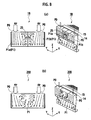
Figs. 8(a) and 8(b) are diagrams showing characteristics of flow rate distributions (vector) at a measured face along the line B-B shown inFig. 7 ; -
Figs. 9(a) and 9(b) are diagrams showing characteristics of static pressure distributions at the measured face along the line B-B shown inFig. 7 ; and -
Fig. 10 is a sectional view of a conventional air conditioner. - An air conditioner according to an embodiment of the present invention will be described with reference to the drawings.
- As shown in
Fig. 1 , anair conditioner 1 of the present embodiment is installed in an instrument panel IP in front of apassenger compartment 2. In other words, theair conditioner 1 is housed between a dash panel DP and the instrument panel IP of the vehicle. Theair conditioner 1 includes an air-blowingunit 4 and an air-conditioning unit 5. - As shown in
Fig. 5 , the air-blowingunit 4 includes acasing 8 having a couple ofscroll chambers 6, 7, which has scroll centers matched to each other, a pair of fans (so called a twin fan) 9, 10 housed in therespective scroll chambers 6, 7, and anelectric motor 12 for driving thefans 9, 10. Thefans 9, 10 are centrifugal sirocco fans. Theelectric motor 12 is disposed between the twofans 9, 10. Theelectric motor 12 has a drive shaft 11 serving as a rotating shaft to rotate thefans 9, 10 so that rotation of the drive shaft 11 of theelectric motor 12 rotates the twofans 9, 10. - As shown in
Fig. 1 , the air-conditioning unit 5 has an air-conditioning case 13. The air-conditioning case 13 defines an air passage P therein. In the air passage P, a plurality of air-conditioning components air filter 14 for collecting foreign particles contained in the air, anevaporator 15 as a cooling heat exchanger, an air mixingdoor device 16 and aheater core 17 as a heating heat exchanger. - The air passage P of the air-
conditioning unit 5 includes, in order from upstream to downstream, an introducing portion P1 extending from an inlet P0 to theair filter 14 andevaporator 15, a portion P3 from theevaporator 15 to the air mixingdoor device 16, a hot air passage P5 and a bypass passage P6 provided downstream the air mixingdoor device 16, an air mixing chamber P7 at a confluence of the hot air passage P5 and bypass passage P6, and outlet passages P8, P9, P10 branched from the air mixing chamber P7. The outlet passages P8, P9, P10 are a defroster outlet passage P8 that opens toward a front window FW of the vehicle and a vent outlet passage P9 that opens toward passenger's upper body and a foot outlet passage P10 that opens toward the passenger's lower body. - The hot air passage P5 and bypass passage P6 are provided in parallel and downstream the air
mixing door device 16. The hot air passage P5 accommodates theheater core 17 as a heating heat exchanger. In contrast, the bypass passage P6 does not have theheater core 17. Thus, when cool air from theevaporator 15 flows through the hot air passage P5, the air is heated and flown to the air mixing chamber P7 as hot air and, when cool air flows through the bypass passage P6, the air flows to the air mixing chamber P7 simply as cool air. - The air
mixing door device 16 adjusts the distribution ratio of the cool air from theevaporator 15 given to the hot air passage P5 and bypass passage P6. The air mixingdoor device 16 is composed of adoor case 16a and a slidingdoor 16b slidably supported by thedoor case 16a. Thedoor case 16a has an opening (not shown) serving as an inlet of the bypass passage P6 and an opening (not shown) serving as an inlet of the hot air passage P5. When the slidingdoor 16b opens the hot air passage P5 and closes the bypass passage P6, as shown inFigs. 1 and2 , all cool air from theevaporator 15 is led to the hot air passage P5. On the other hand, when the slidingdoor 16b closes the hot air passage P5 and opens the bypass passage P6, all cool air from theevaporator 15 is led to the bypass passage P6. Further, when the slidingdoor 16b partially opens both of the hot air passage P5 and bypass passage P6, the cool air from theevaporator 15 flows through the respective of the hot air passage P5 and bypass passage P6. The hot air flown through the hot air passage P5 and the cool air flown through the bypass passage P6 are mixed in the air mixing chamber P7 to provide air having a desired temperature. - The
air conditioner 1 according to the present embodiment has, as shown inFigs. 1 to 4 , apartition plate 25 as a partition extending from the inlet P0 of the air passage P to the most upwind air-conditioning component (theair filter 14, in this example) in the air flow direction in the introducing portion P1 of the air passage. The introducing portion P1 of the air passage P is thus partitioned into a first independent passage P1a and a second independent passage P1b. Further, the passages P5, P6, P7 downstream themixing door device 16 are partitioned into first independent passages and second independent passages by apartition plate 26 as a partition extending in the air flow direction. - The space portion P3 between the
evaporator 15 and mixingdoor device 16 does not include thepartition plates door case 16a of the airmixing door device 16, apartition plate 16c as a partition is provided separately from thepartition plate 26. Thepartition plate 16c is disposed on the same plane as thepartition plate 26 as if thepartition plate 26 is continuously extended. - Here, the introducing
portion P 1 extends in adirection discharge ports scroll chambers 6, 7 extend and in a direction substantially perpendicular to the air flow directions in theevaporator 15 andair filter 14. Thus, the introducing portion P1 extends along the flow direction of the air blown from the air-blowingunit 4 and the air passing through the introducing portion P1 turns at a substantially right angle and flows in to theair filter 14 andevaporator 15. - Effects of the present embodiment will be described.
- When the
electric motor 12 of the air-blowingunit 4 is activated, thefans 9, 10 rotate. When thefans 9, 10 rotate, the air inside and outside thepassenger compartment 2 is introduced into the air-blowingunit 4 and sent to the air-conditioning unit 5 disposed downstream the air-blowingunit 4. - The air sent from the air-blowing
unit 4 to the air-conditioning unit 5 firstly flows through the introducing portion P1 of the air passage P and foreign particles are removed as passing through theair filter 14. Then, the air cleaned by theair filter 14 is cooled by theevaporator 15. The air cooled by theevaporator 15 flows into the air mixingdoor device 16 via the confluence portion P3. The air flown into the air mixingdoor device 16 is distributed to the hot air passage P5 or bypass passage P6, mixed in the air mixing chamber P7 and provided in a desired temperature. The air having a desired temperature is blown from the air mixing chamber P7 into thepassenger compartment 2 via desired outlet passages P8, P9, P10 according an open/close state ofmode selection doors - As described above, the air temperature is controlled in the air mixing
door device 16. For example, a full foot mode can be selected when the slidingdoor 16b closes the bypass passage P6 and opens the hot air passage P5 (seeFigs. 1 and2 ). On the other hand, a full cool mode can be selected when the slidingdoor 16b opens the bypass passage P6 and closes the hot air passage P5. Further, a temperature adjusting mode can be selected when the slidingdoor 16b partially opens the hot air passage P5 and bypass passage P6. - According to the present embodiment, the
partition plate 25 partitions the portion between the inlet P0 to theair filter 14 of the air passage P of the air-conditioning unit 5 into right and left independent passages P1a, P1b. This prevents that the passage cross-section rapidly increases at an area from theindependent discharge ports unit 4 to the introducing portion P1 of the air passage P. In such a structure, when the air from theindependent discharge ports unit 4 flows into the air-conditioning unit 5, a rapidly reduced flow rate or a mutual interference between the air from thedischarge ports air conditioner 1 can be reduced during operation. Further, since the air flowing through theevaporator 15 is guided by thepartition plate 25, an unevenness in the air flow is reduced and the heat transfer efficiency in theevaporator 15 is improved. - For example, according to an experiment, as shown in
Fig. 6 , the air conditioner with thepartition plate Fig. 6 ) has a noise reduction effect of almost 1dBA, compared to an air conditioner withoutpartition plates Fig. 6 ). In particular, around frequency of 315 Hz, a noise reduction of about 1 to 3dBA was observed. -
Fig. 7 shows anair conditioner 1B according to another embodiment of the present invention, which is similar to the air conditioner shown inFigs. 1 to 5 . -
Figs. 8(a) and 8(b) show measured results of flow rate distribution (vector) at a measured face (a portion between the inlet P0 and theair filter 14 of the air passage P) along the line B-B shown inFig. 7 .Figs. 9(a) and 9(b) show measured results of static pressure distribution at the measured face along the line B-B shown inFig. 7 . - Here,
Figs. 8(a) and9(a) show flow rate distribution and static pressure distribution of theair conditioner 1B having thepartition plate 25; andFigs. 8(b) and9(b) show flow rate distribution and static pressure distribution of the air conditioner without a partition plate according to the comparative example. - Compared with the flow rate distribution (
Fig. 8(b) ) of theair conditioner 200 without apartition plate 25, according to the flow rate distribution (Fig. 8(a) ) of theair conditioner 1B having thepartition plate 25, a rapid reduction in flow rate of the air discharged from therespective fans 9, 10 and an interference between the discharged air from the bothfans 9, 10 are reduced. - As described above, the above embodiments are effective to reduce noise of the air conditioner during operation. Further, the air amount sent from the respective fans to the heat exchangers can be made even and the heat transfer efficiency in the heat exchangers can be improved.
- Further, the above embodiments provide air conditioners having a simple structure and reduced cost by simply providing the
partition plate 25 extending in the air flow direction, compared to the conventional art, in which air chambers, a porous bodies and a rib are required. - The above embodiments have the structure including the
partition plate 25 extending at an area between the inlet P0 of the air passage P and theair filter 14 in the air flow direction and theother partition plate 26 extending downstream the air mixingdoor device 16 in the air flow direction; however, it should be appreciated that the present invention is not limited to this example and the present invention may has a structure including thepartition plate 25 without theother partition plate 26. - The present invention is applicable to not only a vehicular air conditioner but also other air conditioners for general machines or industrial machines, for example.
Claims (7)
- An air conditioner comprising:an air-blowing unit including a case defining a pair of independent scroll chambers, and a pair of fans respectively provided in the scroll chambers; andan air-conditioning unit including an air-conditioning case defining an air passage which air from the air-blowing unit flows through, an air-conditioning component provided in the air passage and configured to condition air flowing therethrough, and a partition partitioning a portion of the air passage between an inlet and the most upwind air-conditioning component into a pair of independent passages respectively communicating with the pair of scroll chambers.
- The air conditioner according to claim 1, wherein
the partition is a plate member. - The air conditioner according to claim 1, wherein
the partition extends along a direction of air blown from the air-blowing unit. - The air conditioner according to claim 1, wherein
the partition extends along a direction which discharge ports of the pair of scroll chambers extend. - The air conditioner according to claim 1, wherein
the pair of independent passages extend perpendicular to an air flow direction in the most upwind air-conditioning component. - An air conditioner comprising:an air-blowing unit including a case defining a pair of independent scroll chambers, and a pair of fans respectively provided in the pair of scroll chamber; andan air-conditioning unit including an air-conditioning case defining an air passage which air blown from the air-blowing unit flows through, and air-conditioning components provided in the air passage and configured to condition air therethrough,wherein the air passage of the air-conditioning unit includes an introduction passage between an inlet and a cooling heat exchanger as one of the air-conditioning components, a passage portion between the cooling heat exchanger and an air mixing door device provided downstream the cooling heat exchanger as one of the air-conditioning components, a hot air passage provided downstream the air mixing door device and having a heating heat exchanger as one of the air-conditioning components therein, a bypass passage provided downstream the air mixing door device and not having the heating heat exchanger therein, and an air mixing chamber provided at a confluence portion of the hot air passage and the bypass passage to mix hot air and cool air, and
wherein the air passage of the air-conditioning unit is partitioned into a pair of independent passages that respectively communicate with the pair of scroll chambers, and a confluence portion communicating the pair of independent passages is provided between the cooling heat exchanger and the air mixing door device. - The air conditioner according to claim 6,
the air mixing door device includes a door case, an air mixing door slidably supported by the door case, a partition plate provided in the door case and partitioning a space in the case so that the partitioned spaces respectively continue to the pair of independent passages.
Applications Claiming Priority (2)
| Application Number | Priority Date | Filing Date | Title |
|---|---|---|---|
| JP2005378644A JP2007176391A (en) | 2005-12-28 | 2005-12-28 | Air-conditioning device |
| PCT/JP2006/326112 WO2007074878A1 (en) | 2005-12-28 | 2006-12-27 | Air conditioner |
Publications (1)
| Publication Number | Publication Date |
|---|---|
| EP1967395A1 true EP1967395A1 (en) | 2008-09-10 |
Family
ID=38218100
Family Applications (1)
| Application Number | Title | Priority Date | Filing Date |
|---|---|---|---|
| EP06843494A Withdrawn EP1967395A1 (en) | 2005-12-28 | 2006-12-27 | Air conditioner |
Country Status (6)
| Country | Link |
|---|---|
| US (1) | US20090133422A1 (en) |
| EP (1) | EP1967395A1 (en) |
| JP (1) | JP2007176391A (en) |
| KR (1) | KR20080088615A (en) |
| CN (1) | CN101351349A (en) |
| WO (1) | WO2007074878A1 (en) |
Cited By (1)
| Publication number | Priority date | Publication date | Assignee | Title |
|---|---|---|---|---|
| WO2014095641A1 (en) * | 2012-12-21 | 2014-06-26 | Valeo Systemes Thermiques | Heating, ventilation and/or air-conditioning apparatus |
Families Citing this family (8)
| Publication number | Priority date | Publication date | Assignee | Title |
|---|---|---|---|---|
| JP5220068B2 (en) * | 2010-08-04 | 2013-06-26 | 三菱電機株式会社 | Air conditioner indoor unit and air conditioner |
| JP5568408B2 (en) | 2010-08-23 | 2014-08-06 | 株式会社ケーヒン | Air conditioner for vehicles |
| US9636968B2 (en) | 2011-12-26 | 2017-05-02 | Calsonic Kansei Corporation | Vehicle air conditioner including sub-casing sandwiched by division casings |
| JP2015083449A (en) * | 2013-09-20 | 2015-04-30 | 株式会社デンソー | Air conditioning unit |
| JP6409440B2 (en) * | 2013-11-20 | 2018-10-24 | 株式会社デンソー | Air conditioner |
| JP2015199488A (en) * | 2014-04-01 | 2015-11-12 | 株式会社デンソー | Air conditioner for vehicles |
| JP6434302B2 (en) * | 2014-12-25 | 2018-12-05 | サンデンホールディングス株式会社 | Automotive air conditioner |
| JP6380222B2 (en) * | 2015-04-28 | 2018-08-29 | 株式会社デンソー | Air conditioner for vehicles |
Family Cites Families (8)
| Publication number | Priority date | Publication date | Assignee | Title |
|---|---|---|---|---|
| JPS57130815A (en) * | 1981-02-04 | 1982-08-13 | Nippon Denso Co Ltd | Air conditioner for automobiles |
| JPS63305017A (en) * | 1987-06-05 | 1988-12-13 | Diesel Kiki Co Ltd | Air conditioning device for vehicle |
| JP3395656B2 (en) * | 1997-10-13 | 2003-04-14 | 株式会社デンソー | Vehicle air conditioner |
| FR2774035B1 (en) * | 1998-01-29 | 2000-03-31 | Valeo Climatisation | MOTOR VEHICLE HEATING AND / OR AIR CONDITIONING DEVICE WITH IMPROVED HEAT EXCHANGE MANAGEMENT |
| KR100601835B1 (en) * | 1999-12-30 | 2006-07-19 | 한라공조주식회사 | Automotive Air Conditioning Equipment |
| JP2001270317A (en) * | 2000-03-28 | 2001-10-02 | Calsonic Kansei Corp | Mix door structure of air conditioning unit for vehicle |
| JP4173646B2 (en) * | 2001-03-16 | 2008-10-29 | カルソニックカンセイ株式会社 | Air conditioner for vehicles |
| JP2003080921A (en) * | 2001-09-14 | 2003-03-19 | Calsonic Kansei Corp | Air blower and vehicular air conditioner |
-
2005
- 2005-12-28 JP JP2005378644A patent/JP2007176391A/en not_active Withdrawn
-
2006
- 2006-12-27 EP EP06843494A patent/EP1967395A1/en not_active Withdrawn
- 2006-12-27 KR KR1020087018319A patent/KR20080088615A/en not_active Withdrawn
- 2006-12-27 WO PCT/JP2006/326112 patent/WO2007074878A1/en not_active Ceased
- 2006-12-27 CN CNA2006800497215A patent/CN101351349A/en active Pending
- 2006-12-27 US US12/158,506 patent/US20090133422A1/en not_active Abandoned
Non-Patent Citations (1)
| Title |
|---|
| See references of WO2007074878A1 * |
Cited By (2)
| Publication number | Priority date | Publication date | Assignee | Title |
|---|---|---|---|---|
| WO2014095641A1 (en) * | 2012-12-21 | 2014-06-26 | Valeo Systemes Thermiques | Heating, ventilation and/or air-conditioning apparatus |
| FR2999989A1 (en) * | 2012-12-21 | 2014-06-27 | Valeo Systemes Thermiques | APPARATUS FOR VENTILATION, HEATING AND / OR AIR CONDITIONING |
Also Published As
| Publication number | Publication date |
|---|---|
| US20090133422A1 (en) | 2009-05-28 |
| CN101351349A (en) | 2009-01-21 |
| WO2007074878A1 (en) | 2007-07-05 |
| KR20080088615A (en) | 2008-10-02 |
| JP2007176391A (en) | 2007-07-12 |
Similar Documents
| Publication | Publication Date | Title |
|---|---|---|
| JP6624304B2 (en) | Vehicle air conditioner | |
| CN111247012B (en) | Air conditioner for vehicle | |
| US20080083241A1 (en) | Air conditioning apparatus for vehicle | |
| CN110958953A (en) | Air conditioning unit for vehicle | |
| JP4811385B2 (en) | Air conditioner for vehicles | |
| CN108698479B (en) | Air conditioner for vehicle | |
| EP3524452A1 (en) | Air conditioning unit for vehicle | |
| EP1967395A1 (en) | Air conditioner | |
| EP3335918B1 (en) | Air blowing device | |
| KR20060046558A (en) | Car air conditioner | |
| KR20060104122A (en) | Vehicle Rear Conditioner | |
| CN109906160B (en) | Air conditioning unit for vehicle | |
| KR101156302B1 (en) | Dual zone type air conditioning apparatus for a car | |
| US20070158047A1 (en) | Air conditioner for vehicle | |
| JP2018001911A (en) | Air conditioner | |
| JP2020131959A (en) | Vehicle air conditioning unit | |
| JP6816742B2 (en) | Vehicle air conditioner | |
| KR101705708B1 (en) | Air conditioner for vehicle | |
| CN116766866A (en) | Air conditioner for vehicle | |
| KR102133387B1 (en) | Air conditioner for vehicle | |
| US20070131407A1 (en) | Air conditioning apparatus | |
| JP2002274153A (en) | Vehicle air conditioner | |
| CN113260524A (en) | Air conditioning unit for vehicle | |
| JP7070461B2 (en) | Vehicle air conditioning unit | |
| KR101566307B1 (en) | Rear air conditioner for vehicle |
Legal Events
| Date | Code | Title | Description |
|---|---|---|---|
| PUAI | Public reference made under article 153(3) epc to a published international application that has entered the european phase |
Free format text: ORIGINAL CODE: 0009012 |
|
| 17P | Request for examination filed |
Effective date: 20080624 |
|
| AK | Designated contracting states |
Kind code of ref document: A1 Designated state(s): DE FR GB |
|
| DAX | Request for extension of the european patent (deleted) | ||
| RBV | Designated contracting states (corrected) |
Designated state(s): DE FR GB |
|
| STAA | Information on the status of an ep patent application or granted ep patent |
Free format text: STATUS: THE APPLICATION HAS BEEN WITHDRAWN |
|
| 18W | Application withdrawn |
Effective date: 20091111 |