JP2015199488A - Air conditioner for vehicles - Google Patents

Air conditioner for vehicles Download PDF

Info

Publication number
JP2015199488A
JP2015199488A JP2015041660A JP2015041660A JP2015199488A JP 2015199488 A JP2015199488 A JP 2015199488A JP 2015041660 A JP2015041660 A JP 2015041660A JP 2015041660 A JP2015041660 A JP 2015041660A JP 2015199488 A JP2015199488 A JP 2015199488A
Authority
JP
Japan
Prior art keywords
air
wall
heat exchanger
vehicle
air flow
Prior art date
Legal status (The legal status is an assumption and is not a legal conclusion. Google has not performed a legal analysis and makes no representation as to the accuracy of the status listed.)
Pending
Application number
JP2015041660A
Other languages
Japanese (ja)
Other versions
JP2015199488A5 (en
Inventor
伸一郎 平井
Shinichiro Hirai
伸一郎 平井
哲 犬飼
Satoru Inukai
哲 犬飼
Current Assignee (The listed assignees may be inaccurate. Google has not performed a legal analysis and makes no representation or warranty as to the accuracy of the list.)
Denso Corp
Original Assignee
Denso Corp
Priority date (The priority date is an assumption and is not a legal conclusion. Google has not performed a legal analysis and makes no representation as to the accuracy of the date listed.)
Filing date
Publication date
Application filed by Denso Corp filed Critical Denso Corp
Priority to JP2015041660A priority Critical patent/JP2015199488A/en
Priority to US15/300,547 priority patent/US20170106716A1/en
Priority to PCT/JP2015/001829 priority patent/WO2015151499A1/en
Priority to DE112015001626.0T priority patent/DE112015001626T5/en
Priority to CN201580018137.2A priority patent/CN106170411A/en
Publication of JP2015199488A publication Critical patent/JP2015199488A/en
Publication of JP2015199488A5 publication Critical patent/JP2015199488A5/ja
Pending legal-status Critical Current

Links

Images

Classifications

    • B—PERFORMING OPERATIONS; TRANSPORTING
    • B60—VEHICLES IN GENERAL
    • B60H—ARRANGEMENTS OF HEATING, COOLING, VENTILATING OR OTHER AIR-TREATING DEVICES SPECIALLY ADAPTED FOR PASSENGER OR GOODS SPACES OF VEHICLES
    • B60H1/00—Heating, cooling or ventilating devices
    • B60H1/00007—Combined heating, ventilating, or cooling devices
    • B60H1/00021—Air flow details of HVAC devices
    • B60H1/00028—Constructional lay-out of the devices in the vehicle
    • B—PERFORMING OPERATIONS; TRANSPORTING
    • B60—VEHICLES IN GENERAL
    • B60H—ARRANGEMENTS OF HEATING, COOLING, VENTILATING OR OTHER AIR-TREATING DEVICES SPECIALLY ADAPTED FOR PASSENGER OR GOODS SPACES OF VEHICLES
    • B60H1/00—Heating, cooling or ventilating devices
    • B60H1/00642—Control systems or circuits; Control members or indication devices for heating, cooling or ventilating devices
    • B60H1/00814—Control systems or circuits characterised by their output, for controlling particular components of the heating, cooling or ventilating installation
    • B60H1/00821—Control systems or circuits characterised by their output, for controlling particular components of the heating, cooling or ventilating installation the components being ventilating, air admitting or air distributing devices
    • B60H1/00835—Damper doors, e.g. position control
    • B60H1/00842—Damper doors, e.g. position control the system comprising a plurality of damper doors; Air distribution between several outlets
    • B—PERFORMING OPERATIONS; TRANSPORTING
    • B60—VEHICLES IN GENERAL
    • B60H—ARRANGEMENTS OF HEATING, COOLING, VENTILATING OR OTHER AIR-TREATING DEVICES SPECIALLY ADAPTED FOR PASSENGER OR GOODS SPACES OF VEHICLES
    • B60H1/00—Heating, cooling or ventilating devices
    • B60H1/00007—Combined heating, ventilating, or cooling devices
    • B60H1/00021—Air flow details of HVAC devices
    • B60H2001/00078—Assembling, manufacturing or layout details
    • B60H2001/00092—Assembling, manufacturing or layout details of air deflecting or air directing means inside the device
    • B—PERFORMING OPERATIONS; TRANSPORTING
    • B60—VEHICLES IN GENERAL
    • B60H—ARRANGEMENTS OF HEATING, COOLING, VENTILATING OR OTHER AIR-TREATING DEVICES SPECIALLY ADAPTED FOR PASSENGER OR GOODS SPACES OF VEHICLES
    • B60H1/00—Heating, cooling or ventilating devices
    • B60H1/00007—Combined heating, ventilating, or cooling devices
    • B60H1/00021—Air flow details of HVAC devices
    • B60H2001/00114—Heating or cooling details
    • B60H2001/00135—Deviding walls for separate air flows

Landscapes

  • Physics & Mathematics (AREA)
  • Thermal Sciences (AREA)
  • Engineering & Computer Science (AREA)
  • Mechanical Engineering (AREA)
  • Air-Conditioning For Vehicles (AREA)
  • Air-Flow Control Members (AREA)

Abstract

PROBLEM TO BE SOLVED: To prevent an evaporator front case part 17 from resonating.SOLUTION: An air conditioner 1 for a vehicle includes an electric blower 22 for a single layer flow and an air conditioner case 11. A heat exchanger 30 for cooling is disposed in the air conditioner case 11 and cools an air stream blown out of the electric blower 22 for a single layer flow. A partition 19 is arranged in the evaporator front case part 17 and supported by an opposed wall 18d of the evaporator front case part 17. The evaporator front case part 17 is arranged on an air flow upstream side with respect to the heat exchanger 30 for cooling in the air conditioner case 11. The partition 19 is plate-shaped, formed along the air stream, and partitions the inside of the evaporator front case part 17 into air passages 13a and 13b. By suppressing the displacement of a part of the opposed wall 18d that supports the partition 19, the rigidity of the opposed wall 18d can be enhanced.

Description

本発明は、車両用空調装置に関するものである。   The present invention relates to a vehicle air conditioner.

従来、車両用空調装置の室内空調ユニットでは、電動送風機からエバポレータに吹き出された気流の風速分布が均一になるようにエバポレータ前に風を整流させる空調ケース(以下、エバポレータ前ダクト部という)が設けられているものがある(例えば、特許文献1参照)。   Conventionally, in an indoor air conditioning unit of a vehicle air conditioner, an air conditioning case (hereinafter referred to as an evaporator pre-evaporator) that rectifies the wind in front of the evaporator is provided so that the wind speed distribution of the airflow blown from the electric blower to the evaporator is uniform. (For example, refer to Patent Document 1).

このものにおいて、エバポレータ前ダクト部は、風速分布の均一化を図るために、送風機からの空気流れ上流から下流にしたがって徐々に絞りをいれるような段形状を有している。そして、気流の乱れを発生させないように空調ケース内部には余分な補強用リブ等を設置しないことが一般的である。   In this structure, the duct part in front of the evaporator has a step shape that can be gradually throttled from upstream to downstream of the air flow from the blower in order to make the wind speed distribution uniform. And it is common not to install an extra reinforcing rib or the like inside the air conditioning case so as not to disturb the airflow.

また、近年の車両用空調装置としては、例えば、特許文献2のように、内外気二層流を流通させる室内空調ユニット(以下、内外気二層流型の室内空調ユニットという。)が開発されている。   Further, as a recent vehicle air conditioner, for example, as in Patent Document 2, an indoor air conditioning unit that circulates a two-layer flow of inside and outside air (hereinafter, referred to as a two-layer flow type indoor air-conditioning unit) is developed. ing.

この内外気二層流型の室内空調ユニットでは、送風機から外気を除湿風として取り込むための上層空気通路と、車室内から暖かい気流を取り込むための下層空気通路とを備える。上層空気通路から取り込んだ除湿風をデフロスタを介してウィンドシールドへ吹き出し、車室内から下層空気通路を通して取り込んだ暖風を足元に供給することできる。   This indoor / outside air two-layer flow type indoor air conditioning unit includes an upper air passage for taking outside air from the blower as dehumidified air and a lower air passage for taking warm airflow from the passenger compartment. The dehumidified air taken in from the upper air passage can be blown out to the windshield via the defroster, and the warm air taken in from the passenger compartment through the lower air passage can be supplied to the feet.

この内外気二層流型の室内空調ユニットは、上層空気通路内の除湿風と下層空気通路内の暖風とが混ざらないように、空調ケーシングのうち電動送風機からヒータユニットまで、上層空気通路と下層空気通路との間が仕切り壁によって仕切られている。これに加えて、上記のエバポレータ前ケースも仕切り壁が設けられている。   This indoor / outdoor air two-layer indoor air conditioning unit has an upper air passage from the electric blower to the heater unit in the air conditioning casing so that the dehumidified air in the upper air passage and the warm air in the lower air passage are not mixed. A partition wall separates the lower air passage. In addition, the above-mentioned evaporator front case is also provided with a partition wall.

特開2006−232208号公報JP 2006-232208 A 特開平9−156348号公報JP-A-9-156348

本発明者は、上記特許文献1、2に基づいて、内外気二層流型の室内空調ユニットではなく、単層流用電動送風機から内気および外気のうち少なくとも一方を取り込んで、この取り込んだ空気流を単層流としてエバポレータ側に取り込む単層流型の室内空調ユニットの剛性について検討した。   Based on Patent Documents 1 and 2, the present inventor takes in at least one of the inside air and the outside air from a single laminar electric blower instead of the inside / outside air two-layered room air conditioning unit, We investigated the rigidity of a single laminar flow type air conditioning unit that takes the air into the evaporator as a single laminar flow.

本発明者の検討によれば、エバポレータ前ケース部では、気流の乱れを避けるために、そのケース部内部に余分な補強用リブが設けられていなく、エバポレータ前ケース部の剛性が小さくなっている。このため、単層流用電動送風機の電動モータからの振動がエバポレータ前ケース部に伝達してエバポレータ前ケース部で振動して共振する場合がある。この場合、エバポレータ前ケース部が振動を増幅して異音を発生する発生源になる場合がある。   According to the study of the present inventor, in the case portion before the evaporator, in order to avoid the disturbance of the air flow, no extra reinforcing rib is provided inside the case portion, and the rigidity of the case portion before the evaporator is reduced. . For this reason, the vibration from the electric motor of the electric blower for single-layer flow may be transmitted to the front case portion of the evaporator and vibrate and resonate in the front case portion of the evaporator. In this case, the case part in front of the evaporator may become a generation source that amplifies vibration and generates abnormal noise.

本発明は上記点に鑑みて、単層流用電動送風機から取り込んだ空気流を冷却用熱交換器側に導くように構成されている車両用空調装置において、単層流用電動送風機から伝わる音によって空調ケースが共振することを抑制することを目的とする。   In view of the above, the present invention is a vehicle air conditioner configured to guide an air flow taken from a single-layer flow electric blower to the cooling heat exchanger side, and is air-conditioned by a sound transmitted from the single-layer flow electric blower. The purpose is to suppress the case from resonating.

本発明は、内外気二層流型の室内空調ユニットでは、上層空気通路と下層空気通路とを仕切るために仕切り壁が設けられていることに着目してなされたものである。   The present invention has been made by paying attention to a partition wall provided to partition the upper air passage and the lower air passage in an indoor / outdoor air two-layer indoor air conditioning unit.

具体的には、請求項1に記載の発明では、電動モータ(22a)と、電動モータにより駆動されて車室外空気および車室内空気のうち少なくとも一方を導入して吹き出すファン(22b)と、ファンから吹き出される車室外空気および車室内空気を分け隔てなく流通させる単層の空気流路を構成する送風ケース(22c)と、を備える単層流用電動送風機(22)と、
送風ケースから吹き出される空気流を車室内に向けて流通させる空調ケース(11)と、
空調ケース内に配置されて、送風ケースから吹き出される空気流を冷却する冷却用熱交換器(30)と、
空調ケース内のうち冷却用熱交換器に対して空気流れ上流側に配置され、空調ケース内を第1、第2の通風路(13a、13b、13c、13d、13e、13f)に仕切る仕切り壁(19、84a、84b)と、を備え、
第1、第2の通風路には、送風ケースから吹き出される空気流が流れるようになっており、
空調ケースのうち冷却用熱交換器に対して空気流れ上流側の部位(17)には送風ケースが接続され、
仕切り壁は、空調ケースのうち冷却用熱交換器に対して空気流れ上流側の部位(17)によって支持されるものであって、送風ケースから吹き出される空気流のうち主流の空気流れ方向(S1、S2)に沿うように形成されていることを特徴とする。
Specifically, in the first aspect of the present invention, the electric motor (22a), the fan (22b) driven by the electric motor and introducing and blowing out at least one of the outside air and the air inside the vehicle, and the fan A single-layer flow electric blower (22) comprising: a blower case (22c) that constitutes a single-layer air flow path for circulating outside air and vehicle compartment air blown out from
An air conditioning case (11) for distributing an air flow blown from the air blowing case toward the vehicle interior;
A cooling heat exchanger (30) disposed in the air conditioning case for cooling the air flow blown from the air blowing case;
A partition wall that is disposed upstream of the cooling heat exchanger in the air conditioning case and divides the air conditioning case into first and second ventilation paths (13a, 13b, 13c, 13d, 13e, and 13f). (19, 84a, 84b),
In the first and second ventilation paths, an air flow blown out from the blower case flows,
A ventilation case is connected to the part (17) on the upstream side of the air flow with respect to the cooling heat exchanger in the air conditioning case,
The partition wall is supported by a portion (17) on the upstream side of the air flow with respect to the cooling heat exchanger in the air conditioning case, and the main air flow direction (of the air flow blown out from the blower case) ( It is characterized by being formed along S1, S2).

請求項1に記載の発明によれば、空調ケースのうち冷却用熱交換器に対して空気流れ上流側の部位は、仕切り壁を支持する。このため、空調ケースが振動を生じる際に、空調ケースのうち仕切り壁を支持する部位の変位が抑制されることにより、空調ケースのうち冷却用熱交換器に対して空気流れ上流側の剛性を大きくすることができる。このため、空調ケースのうち冷却用熱交換器に対して空気流れ上流側が電動モータから伝わる振動で共振することを抑制することができる。   According to the first aspect of the present invention, the part on the upstream side of the air flow with respect to the cooling heat exchanger in the air conditioning case supports the partition wall. For this reason, when the air conditioning case is vibrated, the displacement of the part of the air conditioning case that supports the partition wall is suppressed, so that the rigidity of the air flow upstream of the cooling heat exchanger in the air conditioning case is increased. Can be bigger. For this reason, it can suppress that an air flow upstream side resonates with the vibration transmitted from an electric motor with respect to the heat exchanger for cooling among air-conditioning cases.

但し、主流とは、単層流用電動送風機から冷却用熱交換器側に吹き出される複数の空気流のうち最も風量の多い空気流のことである。   However, the main flow is an air flow having the largest air volume among a plurality of air flows blown from the single-layer flow electric blower to the cooling heat exchanger side.

請求項8に記載の発明では、複数の仕切り壁が、空気流れ方向から視たときに互いに重なり合わないように配置されていることを特徴とする。   The invention according to claim 8 is characterized in that the plurality of partition walls are arranged so as not to overlap each other when viewed from the air flow direction.

このため、空調ケースが複数の仕切り壁を支持することになる。したがって、空調ケースの剛性をより一層大きくすることができる。   For this reason, an air-conditioning case will support a plurality of partition walls. Therefore, the rigidity of the air conditioning case can be further increased.

請求項10に記載の発明では、仕切り壁は、主流の流れ方向に沿うようにそれぞれ板状に形成されている複数の板部材(19a、19b、19c)から構成されており、複数の板部材は、空気流れ方向に沿って並ぶように、それぞれ、間隔をあけて配置されていることを特徴とする。   In the invention according to claim 10, the partition wall is composed of a plurality of plate members (19a, 19b, 19c) each formed in a plate shape along the mainstream flow direction. Are characterized by being arranged at intervals so as to be aligned along the air flow direction.

したがって、複数の板部材のそれぞれの間の間隔を通して第1、第2の通風路(13a、13b)の間で空気流が流れる。このため、冷却用熱交換器に流れる空気流において、第1、第2の通風路が並ぶ方向の分布の均一化をより一層向上させることができる。   Therefore, an air flow flows between the first and second ventilation paths (13a, 13b) through the interval between each of the plurality of plate members. For this reason, in the airflow flowing through the cooling heat exchanger, the distribution in the direction in which the first and second ventilation paths are aligned can be further improved.

なお、この欄および特許請求の範囲で記載した各手段の括弧内の符号は、後述する実施形態に記載の具体的手段との対応関係を示すものである。   In addition, the code | symbol in the bracket | parenthesis of each means described in this column and the claim shows the correspondence with the specific means as described in embodiment mentioned later.

本発明の第1実施形態における車両用空調装置の室内空調ユニットの内部の模式図である。It is a schematic diagram inside the indoor air-conditioning unit of the vehicle air conditioner in 1st Embodiment of this invention. 図1中のエバ前ケース部の内部を示す透視図である。It is a perspective view which shows the inside of the front case part in FIG. 図1の車両用空調装置の振動加速度の検証実験結果を示すグラフである。It is a graph which shows the verification experiment result of the vibration acceleration of the vehicle air conditioner of FIG. 図1の車両用空調装置の騒音レベルの検証実験結果を示すグラフである。It is a graph which shows the verification experiment result of the noise level of the vehicle air conditioner of FIG. 本発明の比較例である内外気二層流型の室内空調ユニットの内部を示す透視図である。It is a perspective view which shows the inside of the indoor / outdoor air two-layer flow type indoor air conditioning unit which is a comparative example of the present invention. 第1実施形態の第1変形例における室内空調ユニットの内部の模式図である。It is a schematic diagram inside the indoor air-conditioning unit in the 1st modification of 1st Embodiment. 第1実施形態の第2変形例におけるエバ前ケース部の内部を示す透視図である。It is a perspective view which shows the inside of the pre-evacuation case part in the 2nd modification of 1st Embodiment. 第1実施形態の第2変形例におけるエバ前ケース部内の空気流れを示す透視図である。It is a perspective view which shows the air flow in the pre-evacuation case part in the 2nd modification of 1st Embodiment. 本発明の第2実施形態におけるエバ前ケース部内を示す透視図である。It is a perspective view which shows the inside of a front case part in the second embodiment of the present invention. 第2実施形態の第1変形例におけるエバ前ケース部内を示す透視図である。It is a perspective view which shows the inside of a front case part in the 1st modification of 2nd Embodiment. 本発明の第3実施形態におけるエバ前ケース部の内部を示す透視図である。It is a perspective view which shows the inside of the case part before a evacuation in 3rd Embodiment of this invention. 図11のエバ前ケース部において主流の空気流れ方向に対して直交する断面図である。FIG. 12 is a cross-sectional view orthogonal to the mainstream air flow direction in the front case portion of FIG. 11. 第3実施形態の第1変形例のエバ前ケース部において主流の空気流れ方向に対して直交する断面図である。It is sectional drawing orthogonal to the mainstream air flow direction in the pre-evaporation case part of the 1st modification of 3rd Embodiment. 第3実施形態の第2変形例のエバ前ケース部において主流の空気流れ方向に対して直交する断面図である。It is sectional drawing orthogonal to the mainstream air flow direction in the pre-evaporation case part of the 2nd modification of 3rd Embodiment. 第3実施形態の第3変形例におけるエバ前ケース部の内部を示す透視図である。It is a perspective view which shows the inside of the pre-evacuation case part in the 3rd modification of 3rd Embodiment. 図15において主流の空気流れ方向に対して直交する断面図である。It is sectional drawing orthogonal to the mainstream air flow direction in FIG. 第3実施形態の第4変形例におけるエバ前ケース部の内部を示す透視図である。It is a perspective view which shows the inside of the pre-evacuation case part in the 4th modification of 3rd Embodiment. 図17中A矢視図である。It is A arrow directional view in FIG. 本発明の第4実施形態におけるエバ前ケース部内を示す透視図である。It is a perspective view which shows the inside of a front case part in the fourth embodiment of the present invention. 図19のエバ前ケース部において主流の空気流れ方向に対して直交する断面図である。FIG. 20 is a cross-sectional view orthogonal to the mainstream air flow direction in the front case portion of FIG. 19. 本発明の第4実施形態の第1変形例における車両用空調装置のエバ前ケース部の内部を示す透視図である。It is a perspective view which shows the inside of the front case part of the air conditioner for vehicles in the 1st modification of 4th Embodiment of this invention. 図21中A矢視図である。It is A arrow view in FIG.

以下、本発明の実施形態について図に基づいて説明する。なお、以下の各実施形態相互において、互いに同一もしくは均等である部分には、説明の簡略化を図るべく、図中、同一符号を付してある。   Hereinafter, embodiments of the present invention will be described with reference to the drawings. In the following embodiments, parts that are the same or equivalent to each other are given the same reference numerals in the drawings in order to simplify the description.

(第1実施形態)
車両用空調装置1は、図1に示すように、室内空調ユニット10、およびブロアユニット20を備える。
(First embodiment)
As shown in FIG. 1, the vehicle air conditioner 1 includes an indoor air conditioning unit 10 and a blower unit 20.

室内空調ユニット10は、車室内の計器板(インストルメントパネル)下方部のうち中央部側に配置されている単層流型の室内空調ユニットである。ブロアユニット20は、室内空調ユニット10に対して助手席側へオフセットして配置されている。   The indoor air-conditioning unit 10 is a single-layer flow type indoor air-conditioning unit that is disposed on the center side of the lower part of the instrument panel (instrument panel) in the vehicle interior. The blower unit 20 is arranged offset to the passenger seat side with respect to the indoor air conditioning unit 10.

ブロアユニット20は、内外気切替導入箱21、および単層流用電動送風機22から構成されている単層流用のブロアユニットである。内外気切替導入箱21には、車室外の空気を導入する外気導入口21bと車室内の空気を導入する内気導入口21aとが設けられている。内外気切替導入箱21内には、内外気切替ドア21c、およびフィルタ21dが配置されている。内外気切替ドア21cは、サーボモータ等のアクチェータによって駆動されて、外気導入口21bおよび内気導入口21aのうち一方を開口する。フィルタ21dは、外気導入口21bおよび内気導入口21aのうち一方から導入した空気流を濾過する。   The blower unit 20 is a blower unit for a single laminar flow that includes an inside / outside air switching introduction box 21 and a single layer flow electric blower 22. The inside / outside air switching introduction box 21 is provided with an outside air introduction port 21b for introducing air outside the vehicle compartment and an inside air introduction port 21a for introducing air inside the vehicle compartment. An inside / outside air switching door 21c and a filter 21d are disposed in the inside / outside air switching introduction box 21. The inside / outside air switching door 21c is driven by an actuator such as a servo motor and opens one of the outside air introduction port 21b and the inside air introduction port 21a. The filter 21d filters the air flow introduced from one of the outside air introduction port 21b and the inside air introduction port 21a.

単層流用電動送風機22は、直流モータ22a、単一のファン22b、および、スクロールケーシング22cを備える。直流モータ22aは、スクロールケーシング22cによって支持されて、ファン22bを回転駆動させる。ファン22bは、直流モータ22aによって駆動されて、外気導入口21bおよび内気導入口21aのうち少なくとも一方からフィルタ21dを通して導入した空気を吸入して吹き出す。   The single-layer flow electric blower 22 includes a DC motor 22a, a single fan 22b, and a scroll casing 22c. The DC motor 22a is supported by the scroll casing 22c and rotates the fan 22b. The fan 22b is driven by the DC motor 22a, and sucks and blows in air introduced through the filter 21d from at least one of the outside air introduction port 21b and the inside air introduction port 21a.

本実施形態の単一のファン22bとしては、直流モータ22aの回転軸の軸方向一方側から空気を吸い込んで回転軸の径方向外側に吹き出す遠心式ファンが用いられている。直流モータ22aは、回転軸に支持されている回転子と、モータケースに支持されている固定子とをモータケース内に収納してなる周知のものである。スクロールケーシング22cは、ファン22bを収納し、かつファン22bから吹き出される空気流を集めて吹出口22dに向けて流通させる単層の空気流路を備える。単層の空気流路は、ファン22bから吹き出される車室外空気および車室内空気を分け隔てなく流通させる空気流路である。   As the single fan 22b of the present embodiment, a centrifugal fan that sucks air from one side in the axial direction of the rotating shaft of the DC motor 22a and blows it outward in the radial direction of the rotating shaft is used. The direct current motor 22a is a well-known motor in which a rotor supported by a rotating shaft and a stator supported by a motor case are housed in a motor case. The scroll casing 22c includes a single-layer air flow path that houses the fan 22b and collects an air flow blown from the fan 22b and distributes the air flow toward the air outlet 22d. The single-layer air flow path is an air flow path that allows the outside air and the inside air to be blown out from the fan 22b to flow without being separated.

室内空調ユニット10は、ブロアユニット20から吹き出される空気流を車室内に向けて流通させる空気通路を有する空調ケース11を備える単層流型の室内空調ユニットである。空調ケース11は、吸入口13、フェイス開口部14、フット開口部15、およびデフロスタ開口部16を備える。吸入口13は、空調ケース11のうち冷却用熱交換器30に対して空気流れ上流側に位置するケース部(以下、エバ前ケース部17という)に設けられている。吸入口13には、スクロールケーシング22cの吹出口22dがダクト23を介して接続されている。吸入口13には、スクロールケーシング22cから吹き出される空気流がダクト23を介して吸入される。   The indoor air-conditioning unit 10 is a single-layer flow type indoor air-conditioning unit including an air-conditioning case 11 having an air passage through which an air flow blown from the blower unit 20 is distributed toward the vehicle interior. The air conditioning case 11 includes an inlet 13, a face opening 14, a foot opening 15, and a defroster opening 16. The suction port 13 is provided in a case part (hereinafter referred to as a pre-evaporation case part 17) located on the upstream side of the air flow with respect to the cooling heat exchanger 30 in the air conditioning case 11. An air outlet 22 d of a scroll casing 22 c is connected to the suction port 13 via a duct 23. The air flow blown from the scroll casing 22 c is sucked into the suction port 13 through the duct 23.

なお、ダクト23のうち空気入口を形成する入口形成部がスクロールケーシング22cの出口形成部にねじ等により接続されている。出口形成部は、スクロールケーシング22cのうち空気を吹き出す空気出口を形成する部位である。   Note that an inlet forming portion that forms an air inlet in the duct 23 is connected to an outlet forming portion of the scroll casing 22c by screws or the like. The outlet forming portion is a portion that forms an air outlet that blows out air in the scroll casing 22c.

本実施形態の空調ケース11は、複数の分割ケース部を組み合わせて構成されている。エバ前ケース部17は、複数の分割ケース部のうち1つの分割ケース部を構成していることになる。なお、エバ前ケース部17の具体的な構成については後述する。   The air conditioning case 11 of the present embodiment is configured by combining a plurality of divided case portions. The front case portion 17 constitutes one divided case portion among the plurality of divided case portions. A specific configuration of the pre-evacuation case portion 17 will be described later.

ここで、フェイス開口部14は、フェイス吹出口に空調風を導くための開口部である。フェイス吹出口は、車室内の乗員上半身に空調風を吹き出すための吹出口である。フット開口部15は、フット吹出口に空調風を導くための開口部である。フット吹出口は、車室内の乗員下半身に空調風を吹き出すための吹出口である。デフロスタ開口部16は、デフロスタ吹出口に空調風を導くための開口部である。デフロスタ吹出口は、フロントガラスの内表面に空調風を吹き出すための吹出口である。   Here, the face opening 14 is an opening for guiding conditioned air to the face outlet. The face air outlet is an air outlet for blowing air-conditioning air on the upper body of the passenger in the passenger compartment. The foot opening 15 is an opening for guiding the conditioned air to the foot outlet. The foot outlet is an outlet for blowing conditioned air to the passenger's lower body in the passenger compartment. The defroster opening 16 is an opening for guiding the conditioned air to the defroster outlet. The defroster outlet is an outlet for blowing conditioned air to the inner surface of the windshield.

空調ケース11内には、冷却用熱交換器30、加熱用熱交換器40、およびモードドア60、61、62が配置されている。   In the air conditioning case 11, a cooling heat exchanger 30, a heating heat exchanger 40, and mode doors 60, 61, 62 are arranged.

冷却用熱交換器30は、圧縮機、凝縮器、減圧弁等とともに、冷媒を循環させる冷凍サイクルを構成するもので、吸入口13から導入した空気を冷媒によって冷却する。冷却用熱交換器30は、第1、第2のタンク、複数本のチューブ、および熱交換フィンによって扁平形状に形成されている。冷却用熱交換器30は、立てた状態で配置されている。冷却用熱交換器30の扁平方向は、車幅方向(車両左右方向)に平行になっている。扁平方向とは、厚み方向に直交して冷却用熱交換器30が拡がる方向のことである。   The cooling heat exchanger 30 constitutes a refrigeration cycle in which a refrigerant is circulated together with a compressor, a condenser, a pressure reducing valve, and the like, and cools air introduced from the suction port 13 with the refrigerant. The cooling heat exchanger 30 is formed in a flat shape by first and second tanks, a plurality of tubes, and heat exchange fins. The cooling heat exchanger 30 is arranged in an upright state. The flat direction of the cooling heat exchanger 30 is parallel to the vehicle width direction (vehicle left-right direction). The flat direction is a direction in which the cooling heat exchanger 30 extends perpendicular to the thickness direction.

加熱用熱交換器40は、冷却用熱交換器30に対して空気下流側に配置されて、エンジン冷却水(温水)によって冷却用熱交換器30を通過した空気を加熱する。冷却用熱交換器30、および加熱用熱交換器40は、空調ケース11によって支持されている。   The heat exchanger 40 for heating is arrange | positioned in the air downstream with respect to the heat exchanger 30 for cooling, and heats the air which passed the heat exchanger 30 for cooling with engine cooling water (warm water). The cooling heat exchanger 30 and the heating heat exchanger 40 are supported by the air conditioning case 11.

空調ケース11には、冷却用熱交換器30から流れる冷風を加熱用熱交換器40をバイパスして各吹出開口部に流すバイパス通路35a、35bが設けられている。バイパス通路35aは、空調ケース11のうち加熱用熱交換器40の上側に設けられている。バイパス通路35bは、空調ケース11のうち加熱用熱交換器40の下側に設けられている。   The air-conditioning case 11 is provided with bypass passages 35a and 35b that allow the cold air flowing from the cooling heat exchanger 30 to bypass the heating heat exchanger 40 and flow to the outlet openings. The bypass passage 35 a is provided above the heating heat exchanger 40 in the air conditioning case 11. The bypass passage 35 b is provided below the heating heat exchanger 40 in the air conditioning case 11.

加熱用熱交換器40および冷却用熱交換器30の間には、エアミックスドア37a、37bが設けられている。エアミックスドア37aは、バイパス通路35aを通過する空気量と、加熱用熱交換器40を通過する空気量との比率を変える。エアミックスドア37bは、バイパス通路35bを通過する空気量と、加熱用熱交換器40を通過する空気量との比率を変える。このように作動するエアミックスドア37a、37bによって、開口部14、15、16を通して車室内に吹き出される空気温度を変えることができる。開口部14、15、16は、フェイス開口部14、フット開口部15、およびデフロスタ開口部16を総称したものである。   Air mix doors 37a and 37b are provided between the heat exchanger 40 for heating and the heat exchanger 30 for cooling. The air mix door 37a changes the ratio of the amount of air passing through the bypass passage 35a and the amount of air passing through the heat exchanger 40 for heating. The air mix door 37b changes the ratio of the amount of air passing through the bypass passage 35b and the amount of air passing through the heat exchanger 40 for heating. The air temperature blown into the vehicle interior through the openings 14, 15, 16 can be changed by the air mix doors 37a, 37b operating in this way. The openings 14, 15, and 16 are a general term for the face opening 14, the foot opening 15, and the defroster opening 16.

空調ケース11には、仕切り壁41、42が設けられている。仕切り壁41は、空調ケース11のうち加熱用熱交換器40および冷却用熱交換器30の間の空気通路を上側通風路13aと下側通風路13b(図1参照)とに仕切る。仕切り壁42は、空調ケース11のうち加熱用熱交換器40の空気下流側を上側通風路13aと下側通風路13bとに仕切る。空調ケース11のうち仕切り壁41に対して空気下流側には、上側通風路13aと下側通風路13bとの間を連通する開口部43が設けられている。   The air conditioning case 11 is provided with partition walls 41 and 42. The partition wall 41 partitions the air passage between the heating heat exchanger 40 and the cooling heat exchanger 30 in the air conditioning case 11 into an upper ventilation passage 13a and a lower ventilation passage 13b (see FIG. 1). The partition wall 42 partitions the air downstream side of the heating heat exchanger 40 in the air conditioning case 11 into an upper ventilation path 13a and a lower ventilation path 13b. An opening 43 that communicates between the upper ventilation path 13 a and the lower ventilation path 13 b is provided on the air downstream side of the partition wall 41 in the air conditioning case 11.

モードドア60は、空調ケース11に支持されて、デフロスタ開口部16を開閉する。モードドア61は、空調ケース11に支持されて、フェイス開口部14を開閉する。モードドア62は、空調ケース11に支持されて、フット開口部15および開口部43のうちいずれか一方を開けて、他方の開口部を閉じる。   The mode door 60 is supported by the air conditioning case 11 and opens and closes the defroster opening 16. The mode door 61 is supported by the air conditioning case 11 and opens and closes the face opening 14. The mode door 62 is supported by the air conditioning case 11 and opens one of the foot opening 15 and the opening 43 and closes the other opening.

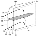
次に、本実施形態のエバ前ケース部17の詳細について図2を参照して説明する。   Next, details of the pre-evacuation case portion 17 of the present embodiment will be described with reference to FIG.

エバ前ケース部17は、空調ケース11のうちダクト23が接続される接続部13X(図2参照)から冷却用熱交換器30に至る上流側ケース部を構成している。接続部13Xは、空調ケース11のうち吸入口13を形成する吸入口形成部である。吸入口形成部には、ダクト23のうち出口形成部がねじ等の締結部材により接続される。出口形成部は、ダクト23のうち空気流を吹き出す出口を形成する部位である。ダクト23は、スクロールケーシング22cとともに、本発明の送風ケースを構成する。吸入口形成部は、後述する上壁18a、下壁18b、および対向壁18dによって形成されている。   The front case portion 17 constitutes an upstream case portion from the connection portion 13X (see FIG. 2) to which the duct 23 is connected in the air conditioning case 11 to the heat exchanger 30 for cooling. The connection portion 13 </ b> X is a suction port forming portion that forms the suction port 13 in the air conditioning case 11. The outlet forming portion of the duct 23 is connected to the suction port forming portion by a fastening member such as a screw. The outlet forming portion is a portion that forms an outlet for blowing out an air flow in the duct 23. The duct 23 constitutes the blower case of the present invention together with the scroll casing 22c. The suction port forming portion is formed by an upper wall 18a, a lower wall 18b, and an opposing wall 18d described later.

具体的には、エバ前ケース部17は、上壁18a、下壁18b、側壁18c、および対向壁18dを備える。上壁18aは、冷却用熱交換器30に対して車両前側に位置する。上壁18aは、側壁18c、対向壁18d、および冷却用熱交換器30に対して天地方向上側に配置されている。   Specifically, the front case portion 17 includes an upper wall 18a, a lower wall 18b, a side wall 18c, and an opposing wall 18d. The upper wall 18 a is located on the vehicle front side with respect to the cooling heat exchanger 30. The upper wall 18a is disposed on the heaven region improvement side with respect to the side wall 18c, the opposing wall 18d, and the cooling heat exchanger 30.

下壁18bは、冷却用熱交換器30に対して車両前側に配置されている。下壁18bは、側壁18c、対向壁18d、および冷却用熱交換器30に対して天地方向下側に配置されている。   The lower wall 18b is disposed on the front side of the vehicle with respect to the cooling heat exchanger 30. The lower wall 18b is disposed on the lower side in the vertical direction with respect to the side wall 18c, the opposing wall 18d, and the cooling heat exchanger 30.

対向壁18dは、空気流入面31に対向している。すなわち、対向壁18dは、空気流入面31の法線方向に位置する。空気流入面31は、冷却用熱交換器30のうち、上側通風路13aおよび下側通風路13bをそれぞれ通過した空気流が流入する面である。本実施形態の対向壁18dは、冷却用熱交換器30の空気流入面31に対して車両前側に位置している。対向壁18dは、空気流れ上流側から下流側に向かうほど冷却用熱交換器30の空気流入面31側に近づくように階段状に形成されている。そして、対向壁18dのうち上側18eは、天地方向上側に向かうほど冷却用熱交換器30の空気流入面31側に近づくように傾斜している。   The facing wall 18d faces the air inflow surface 31. That is, the facing wall 18 d is located in the normal direction of the air inflow surface 31. The air inflow surface 31 is a surface into which the air flow which each passed through the upper side ventilation path 13a and the lower side ventilation path 13b flows in the heat exchanger 30 for cooling. The opposing wall 18d of the present embodiment is located on the vehicle front side with respect to the air inflow surface 31 of the cooling heat exchanger 30. The opposing wall 18d is formed in a stepped shape so as to approach the air inflow surface 31 side of the cooling heat exchanger 30 as it goes from the air flow upstream side to the downstream side. Then, the upper side 18e of the facing wall 18d is inclined so as to approach the air inflow surface 31 side of the cooling heat exchanger 30 as it goes toward the heaven region improvement side.

吸入口13は、上壁18a、下壁18b、および対向壁18d等によって形成されるもので、車幅方向一方側(助手席側)に開口している。つまり、吸入口13は、冷却用熱交換器30の空気流入面31の面方向の一方側に開口している。換言すれば、吸入口形成部は、冷却用熱交換器30の空気流入面31の面方向の一方側に配置されている。   The suction port 13 is formed by the upper wall 18a, the lower wall 18b, the opposing wall 18d, and the like, and is open on one side (passenger seat side) in the vehicle width direction. That is, the suction port 13 is open on one side in the surface direction of the air inflow surface 31 of the cooling heat exchanger 30. In other words, the suction port forming portion is disposed on one side in the surface direction of the air inflow surface 31 of the cooling heat exchanger 30.

空気流入面31の面方向とは、空気流入面31が拡がる方向である。側壁18cは、冷却用熱交換器30に対して車両前側で、かつ車幅方向他方側に配置されている。つまり、側壁18cは、空気流入面31に対して吸入口13(すなわち、吸入口形成部)の反対側に配置されている。   The surface direction of the air inflow surface 31 is a direction in which the air inflow surface 31 expands. The side wall 18c is disposed on the vehicle front side and the other side in the vehicle width direction with respect to the cooling heat exchanger 30. That is, the side wall 18c is disposed on the opposite side of the air inlet 13 (that is, the inlet port forming portion) with respect to the air inflow surface 31.

本実施形態のエバ前ケース部17内には、仕切り壁19が設けられている。仕切り壁19は、ブロアユニット20から吹き出される空気流のうち主流の流れ方向(図2中矢印S1、S2参照)に沿うように板状に形成されている。つまり、仕切り壁19は、主流の流れ方向に対して平行に配置されている。主流は、ブロアユニット20から冷却用熱交換器30側に吹き出される複数の空気流のうち最も風量の多い空気流のことである。   A partition wall 19 is provided in the front case portion 17 of the present embodiment. The partition wall 19 is formed in a plate shape so as to follow the main flow direction (see arrows S1 and S2 in FIG. 2) of the air flow blown from the blower unit 20. That is, the partition wall 19 is arranged in parallel to the mainstream flow direction. The main flow is an air flow having the largest air volume among a plurality of air flows blown from the blower unit 20 to the cooling heat exchanger 30 side.

仕切り壁19は、側壁18cおよび対向壁18dによって支持されている。仕切り壁19は、エバ前ケース部17内を上側通風路13aと下側通風路13bとに仕切るために、水平方向に平行に配置されている。このことにより、仕切り壁19は、ブロアユニット20から吹き出される空気流のうち主流の空気流れ方向に沿うように形成されていることになる。   The partition wall 19 is supported by the side wall 18c and the opposing wall 18d. The partition wall 19 is arranged in parallel in the horizontal direction in order to partition the inside of the front case portion 17 into an upper ventilation path 13a and a lower ventilation path 13b. As a result, the partition wall 19 is formed along the main air flow direction of the air flow blown out from the blower unit 20.

次に、本実施形態の車両用空調装置1の作動について説明する。   Next, the operation of the vehicle air conditioner 1 of the present embodiment will be described.

まず、ブロアユニット20の単層流用電動送風機22では、直流モータ22aがファン22bを回転する。内外気切替ドア21cは、外気導入口21bおよび内気導入口21aのうち一方を開口している。このため、ファン22bが外気導入口21bおよび内気導入口21aのうち少なくも一方から空気を流入して吹出口22dから吹き出す。   First, in the single layer flow electric blower 22 of the blower unit 20, the DC motor 22a rotates the fan 22b. The inside / outside air switching door 21c opens one of the outside air introduction port 21b and the inside air introduction port 21a. For this reason, the fan 22b flows in air from at least one of the outside air inlet 21b and the inside air inlet 21a and blows it out from the outlet 22d.

この吹出口22dから吹き出された空気は、スクロールケーシング22c、ダクト23、および吸入口13を介してエバ前ケース部17内に流れる。このように流れる空気は、仕切り壁19を挟んだ上側通風路13aと下側通風路13bとに分流される。   The air blown out from the air outlet 22d flows into the front case portion 17 through the scroll casing 22c, the duct 23, and the suction port 13. The air flowing in this way is divided into an upper ventilation path 13a and a lower ventilation path 13b with the partition wall 19 in between.

例えば、内外気切替ドア21cにより外気導入口21bを閉じて内気導入口21aを開けた場合には、ファン22bは、内気導入口21aを介して車室内空気を導入してこの車室内空気を吹き出す。このため、この吹き出される車室内空気がスクロールケーシング22c、ダクト23、および吸入口13を介して上側通風路13aおよび下側通風路13bのそれぞれに流れる。   For example, when the outside air introduction port 21b is closed by the inside / outside air switching door 21c and the inside air introduction port 21a is opened, the fan 22b introduces vehicle interior air through the inside air introduction port 21a and blows out the vehicle interior air. . For this reason, the blown-out vehicle interior air flows through the scroll casing 22c, the duct 23, and the suction port 13 to the upper ventilation path 13a and the lower ventilation path 13b, respectively.

また、内外気切替ドア21cにより外気導入口21bを開けて内気導入口21aを閉じた場合には、ファン22bは、外気導入口21bを介して車室外空気を導入してこの車室外空気を吹き出す。このため、この吹き出される車室外空気が
スクロールケーシング22c、ダクト23、および吸入口13を介して上側通風路13aおよび下側通風路13bのそれぞれに流れる。
Further, when the outside air introduction port 21b is opened by the inside / outside air switching door 21c and the inside air introduction port 21a is closed, the fan 22b introduces the outside air through the outside air introduction port 21b and blows out this outside air. . For this reason, the blown-out vehicle exterior air flows through the scroll casing 22c, the duct 23, and the suction port 13 to the upper ventilation path 13a and the lower ventilation path 13b, respectively.

さらに、内外気切替ドア21cにより外気導入口21bおよび内気導入口21aを開けた場合には、ファン22bは、外気導入口21bを介して車室外空気を導入するとともに、内気導入口21aを介して車室内空気を導入して、これら導入した車室外空気および車室内空気を吹き出す。この吹き出される車室外空気および車室外空気は、スクロールケーシング22cおよびダクト23内を分け隔てなく流通する。これに伴い、この流通した車室外空気および車室内空気は、吸入口13を介して上側通風路13aおよび下側通風路13bのそれぞれに流れる。   Further, when the outside air introduction port 21b and the inside air introduction port 21a are opened by the inside / outside air switching door 21c, the fan 22b introduces outside air through the outside air introduction port 21b and also through the inside air introduction port 21a. The vehicle interior air is introduced, and the introduced vehicle exterior air and vehicle interior air are blown out. The air outside the vehicle compartment and the air outside the vehicle compartment are blown through the scroll casing 22c and the duct 23 without being separated. Along with this, the circulated vehicle exterior air and vehicle interior air flow to the upper ventilation path 13a and the lower ventilation path 13b through the suction port 13, respectively.

以上のように単層流用電動送風機22から吹き出される空気流は、吸入口13を介して上側通風路13aおよび下側通風路13bのそれぞれに流れる。   As described above, the air flow blown out from the single-layer flow electric blower 22 flows to the upper ventilation path 13a and the lower ventilation path 13b through the suction port 13, respectively.

このため、上側通風路13a内の空気流は、主に、図2中矢印S1の如く、冷却用熱交換器30に流れる。下側通風路13b内の空気流は、主に、図2中矢印S2の如く、冷却用熱交換器30に流れる。   For this reason, the air flow in the upper ventilation path 13a mainly flows into the cooling heat exchanger 30 as shown by an arrow S1 in FIG. The air flow in the lower ventilation path 13b mainly flows into the cooling heat exchanger 30 as shown by an arrow S2 in FIG.

このように流れる上側通風路13a内の空気流と下側通風路13b内の空気流とは、冷却用熱交換器30に流れる。これに伴い、冷却用熱交換器30で空気流が冷媒により冷却されて冷却用熱交換器30から冷風が吹き出される。この冷風のうち一部は、加熱用熱交換器40に流れる。これにより、冷却用熱交換器30から吹き出される冷風の一部は、加熱用熱交換器40でエンジン冷却水により加熱される。このため、加熱用熱交換器40から温風が吹き出されて開口部14、15、16側に流れる。一方、冷却用熱交換器30からの冷風のうち加熱用熱交換器40に流れる冷風以外の残りの冷風は、バイパス通路35a、35bを通して開口部14、15、16側に流れる。   The air flow in the upper ventilation path 13 a and the air flow in the lower ventilation path 13 b flowing in this way flow to the cooling heat exchanger 30. Accordingly, the cooling heat exchanger 30 cools the air flow with the refrigerant, and cool air is blown out from the cooling heat exchanger 30. A part of the cold air flows to the heat exchanger 40 for heating. Thereby, a part of the cold air blown out from the cooling heat exchanger 30 is heated by the engine cooling water in the heating heat exchanger 40. For this reason, warm air is blown out from the heating heat exchanger 40 and flows toward the openings 14, 15 and 16. On the other hand, of the cold air from the cooling heat exchanger 30, the remaining cold air other than the cold air flowing to the heating heat exchanger 40 flows to the openings 14, 15, and 16 through the bypass passages 35 a and 35 b.

このため、加熱用熱交換器40から吹き出される温風とバイパス通路35bを通過した冷風とは混合されてフット開口部15から吹き出される。加熱用熱交換器40から吹き出される温風とバイパス通路35aを通過した冷風とは混合されてフェイス開口部14から吹き出される。加熱用熱交換器40から吹き出される温風とバイパス通路35a、35bを通過した冷風とは混合されてデフロスタ開口部16から吹き出される。   For this reason, the warm air blown from the heating heat exchanger 40 and the cold air passing through the bypass passage 35 b are mixed and blown out from the foot opening 15. The hot air blown from the heat exchanger 40 for heating and the cold air that has passed through the bypass passage 35 a are mixed and blown out from the face opening 14. The hot air blown out from the heat exchanger 40 for heating and the cold air that has passed through the bypass passages 35 a and 35 b are mixed and blown out from the defroster opening 16.

このとき、直流モータ22aがファン22bを回転させる際に振動を発生させる。例えば、直流モータ22aでは、回転子が通電された状態で、固定子(すなわち、永久磁石)から磁界を受けて回転子の回転力を発生させる。このため、直流モータ22aの回転軸がファン22bを回転させる。この際に、モータケースは、磁束を通過させるヨークとして機能させる。モータケースは、固定子を支持しているため、回転子および固定子の間の電磁力により伸縮がモータケースに生じる。このとき、モータケースには、回転子の極数や回転数に応じた周波数の振動が生じる。この振動は、直流モータ22aからスクロールケーシング22cおよびダクト23を介して空調ケース11側に伝わる。   At this time, vibration is generated when the DC motor 22a rotates the fan 22b. For example, in the direct current motor 22a, the rotor is energized to receive a magnetic field from a stator (that is, a permanent magnet) and generate a rotational force of the rotor. For this reason, the rotating shaft of the DC motor 22a rotates the fan 22b. At this time, the motor case functions as a yoke that allows magnetic flux to pass therethrough. Since the motor case supports the stator, expansion and contraction occurs in the motor case due to electromagnetic force between the rotor and the stator. At this time, vibration with a frequency corresponding to the number of poles and the number of rotations of the rotor occurs in the motor case. This vibration is transmitted from the DC motor 22a to the air conditioning case 11 side through the scroll casing 22c and the duct 23.

例えば、エバ前ケース部17内に仕切り壁19が設けられていない場合には、直流モータ22a側から伝わる振動が起因して、対向壁18dが共振して、"いわゆる磁気音”を発生する場合がある。   For example, when the partition wall 19 is not provided in the front case portion 17, the opposing wall 18 d resonates due to vibration transmitted from the DC motor 22 a side to generate “so-called magnetic sound”. There is.

これに対して、本実施形態では、エバ前ケース部17内に仕切り壁19が設けられている。このため、対向壁18dのうち仕切り壁19を支持している部位の変位が抑制されることにより、対向壁18d、ひいては、エバ前ケース部17の剛性を大きくすることができる。このため、直流モータ22a側から伝わる振動によって対向壁18dが共振しなくなる。   On the other hand, in the present embodiment, a partition wall 19 is provided in the front case portion 17. For this reason, the rigidity of the opposing wall 18d and by extension, the front case part 17 can be increased by suppressing the displacement of the part of the opposing wall 18d that supports the partition wall 19. For this reason, the opposing wall 18d does not resonate due to vibration transmitted from the DC motor 22a side.

以上説明した本実施形態によれば、車両用空調装置1は、車室外空気および車室内空気のうち少なくとも一方を導入して吹き出す単層流用電動送風機22と、ブロアユニット20から吹き出される1つの空気流を車室内に向けて流通させる空気通路を有する空調ケース11とを備える単層流型の室内空調ユニット10とを備える。単層流用電動送風機22は、直流モータ22aと、直流モータ22aにより駆動されて車室外空気および車室内空気のうち少なくとも一方を導入して吹き出すファン22bと、ファン22bから吹き出される車室外空気および車室内空気を分け隔てなく流通させる単層の空気流路を構成するスクロールケーシング22cとを備える。冷却用熱交換器30は、空調ケース11内に配置されて、ブロアユニット20から吹き出される空気流を冷却する。仕切り壁19は、エバ前ケース部17によって支持されるものである。仕切り壁19は、エバ前ケース部17内を上側通風路13aおよび下側通風路13bに仕切る板状に設けられている。仕切り壁19は、板状で、かつブロアユニット20から吹き出される空気流のうち主流の空気流れ方向に沿うように形成されている。このため、上側通風路13aおよび下側通風路13bには、ブロアユニット20から吹き出される空気流が分流して流れることを特徴とする。   According to the above-described embodiment, the vehicle air conditioner 1 includes the single-layer flow electric blower 22 that introduces and blows out at least one of the outside air and the inside air of the vehicle, and one blown out from the blower unit 20. And a single-layer flow type indoor air conditioning unit 10 including an air conditioning case 11 having an air passage for flowing an air flow toward the vehicle interior. The single-layer flow electric blower 22 includes a DC motor 22a, a fan 22b that is driven by the DC motor 22a to introduce and blow out at least one of vehicle exterior air and vehicle interior air, vehicle exterior air blown from the fan 22b, and And a scroll casing 22c that constitutes a single-layer air passage through which the air in the vehicle compartment flows without being separated. The cooling heat exchanger 30 is disposed in the air conditioning case 11 and cools the air flow blown out from the blower unit 20. The partition wall 19 is supported by the front case portion 17. The partition wall 19 is provided in a plate shape that partitions the front case portion 17 into an upper ventilation path 13a and a lower ventilation path 13b. The partition wall 19 is plate-shaped and is formed along the main air flow direction of the air flow blown out from the blower unit 20. For this reason, the air flow blown out from the blower unit 20 is divided and flows in the upper ventilation path 13a and the lower ventilation path 13b.

以上によれば、側壁18cおよび対向壁18dによって仕切り壁19を支持している。このため、対向壁18dのうち仕切り壁19を支持している部位の変位が抑制されることにより、対向壁18dの剛性を大きくすることができる。さらに、仕切り壁19は、側壁18cにより支持されているので、対向壁18dの剛性をより一層大きくすることができる。このため、エバ前ケース部17が対向壁18dが単層流用電動送風機22から伝わる振動で共振することを抑制することができる。これに伴い、エバ前ケース部17の共振により騒音を発生して乗員に違和感を与えることを避けることができる。   According to the above, the partition wall 19 is supported by the side wall 18c and the opposing wall 18d. For this reason, the rigidity of the opposing wall 18d can be increased by suppressing the displacement of the portion of the opposing wall 18d that supports the partition wall 19. Furthermore, since the partition wall 19 is supported by the side wall 18c, the rigidity of the opposing wall 18d can be further increased. For this reason, it is possible to prevent the front case portion 17 from resonating with the vibration transmitted from the single-layer flow electric blower 22 by the opposing wall 18d. Along with this, it is possible to avoid generating noise due to resonance of the front case portion 17 and giving the passenger a sense of incongruity.

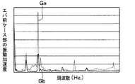
図3、図4に、本実施形態の車両用空調装置1の検証実験の測定値を示す。図3中のグラフGa、Gbは、エバ前ケース部17の振動加速度と周波数との関係を示すグラフである。図4中のグラフGc、Gdは、車室内の騒音レベルと周波数との関係を示すグラフである。グラフGa、Gdは、エバ前ケース部17内に仕切り壁19が設けていない比較例としての車両用空調装置の検証実験の測定値である。グラフGb、Gcは、エバ前ケース部17内に仕切り壁19が設けた本実施形態の車両用空調装置1の検証実験の測定値である。   3 and 4 show measured values of the verification experiment of the vehicle air conditioner 1 of the present embodiment. Graphs Ga and Gb in FIG. 3 are graphs showing the relationship between the vibration acceleration and the frequency of the front case portion 17. Graphs Gc and Gd in FIG. 4 are graphs showing the relationship between the noise level in the passenger compartment and the frequency. Graphs Ga and Gd are measured values of a verification experiment of a vehicle air conditioner as a comparative example in which the partition wall 19 is not provided in the front case portion 17. Graphs Gb and Gc are measured values of a verification experiment of the vehicle air conditioner 1 of the present embodiment in which the partition wall 19 is provided in the front case portion 17.

図3中のグラフGa、Gbおよび図4中のグラフGc、Gdから分かるように、仕切り壁19によって、エバ前ケース部17の振動加速度のピ−クを大幅に低減し、かつ騒音レベルのピ−クを大幅に低減していることが分かる。   As can be seen from the graphs Ga and Gb in FIG. 3 and the graphs Gc and Gd in FIG. 4, the partition wall 19 significantly reduces the peak of the vibration acceleration of the front case portion 17 and the noise level peak. -It can be seen that the drastic reduction is greatly reduced.

本実施形態では、仕切り壁19が、上述の如く、エバ前ケース部17内を上側通風路13aおよび下側通風路13bに仕切る板状に設けられている。よって、本実施形態のエバ前ケース部17を二層流型の室内空調ユニット10Aに用いることができる。このため、単層流用の室内空調ユニット10と二層流型の室内空調ユニット10A(図5参照)とに同一のエバ前ケース部17を共通して使用することができる。   In the present embodiment, the partition wall 19 is provided in a plate shape that partitions the inside of the front case portion 17 into the upper ventilation path 13a and the lower ventilation path 13b as described above. Therefore, the front case portion 17 of the present embodiment can be used for the two-layered indoor air conditioning unit 10A. For this reason, the same front case part 17 can be used in common for the indoor air-conditioning unit 10 for single-layer flow and the indoor air-conditioning unit 10A (see FIG. 5) of the two-layer flow type.

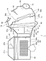
なお、以下、二層流型の室内空調ユニット10Aの概略について図5を参照して説明する。   Hereinafter, an outline of the two-layer flow type indoor air conditioning unit 10A will be described with reference to FIG.

二層流型の室内空調ユニット10Aとは、二層流用ブロアユニット20Aから吹き出される二層の空気流を車室内に向けて流通させる空気通路を有する空調ケース11を備える。図5中の空調ケース11、冷却用熱交換器30、加熱用熱交換器40、およびモードドア60、61、62は、図1中の空調ケース11、冷却用熱交換器30、加熱用熱交換器40、およびモードドア60、61、62と同一である。   The two-layer flow type indoor air-conditioning unit 10A includes an air-conditioning case 11 having an air passage through which a two-layer air flow blown from the two-layer flow blower unit 20A flows toward the vehicle interior. The air conditioning case 11, the cooling heat exchanger 30, the heating heat exchanger 40, and the mode doors 60, 61, 62 in FIG. 5 are the air conditioning case 11, the cooling heat exchanger 30, and the heating heat in FIG. It is the same as the exchanger 40 and the mode doors 60, 61, 62.

二層流用ブロアユニット20Aは、内外気切替導入箱21Aおよび、二層流型の電動送風機22Aから構成されている。内外気切替導入箱21Aには、空気通路21h、21jが設けられている。内外気切替導入箱21Aには、車室外の空気を導入する外気導入口21bと車室内の空気を導入する内気導入口21a、21gとが設けられている。   The two-layer flow blower unit 20A includes an inside / outside air switching introduction box 21A and a two-layer flow type electric blower 22A. In the inside / outside air switching introduction box 21A, air passages 21h and 21j are provided. The inside / outside air switching introduction box 21A is provided with an outside air introduction port 21b for introducing air outside the vehicle compartment and inside air introduction ports 21a and 21g for introducing air inside the vehicle compartment.

外気導入口21bおよび内気導入口21aは、空気通路21h側に設けられており、内気導入口21gは、空気通路21jに設けられている。内外気切替導入箱21内には、内外気切替ドア21c、21eおよびフィルタ21dが配置されている。内外気切替ドア21cは、サーボモータ等のアクチェータによって駆動されて、外気導入口21bおよび内気導入口21aのうち一方を開口する。内気切替ドア21eは、サーボモータ等のアクチェータによって駆動されて、内気導入口21gおよび空気通路21fのうち一方を開閉する。空気通路21fは、内外気切替導入箱21Aのうち空気通路21h、21jの間に設けられている。フィルタ21dは、外気導入口21bおよび内気導入口21a、21gから導入した空気流を濾過する。   The outside air introduction port 21b and the inside air introduction port 21a are provided on the air passage 21h side, and the inside air introduction port 21g is provided on the air passage 21j. Inside / outside air switching introduction box 21 is arranged inside / outside air switching doors 21c, 21e and a filter 21d. The inside / outside air switching door 21c is driven by an actuator such as a servo motor and opens one of the outside air introduction port 21b and the inside air introduction port 21a. The inside air switching door 21e is driven by an actuator such as a servo motor, and opens or closes one of the inside air introduction port 21g and the air passage 21f. The air passage 21f is provided between the air passages 21h and 21j in the inside / outside air switching introduction box 21A. The filter 21d filters the air flow introduced from the outside air inlet 21b and the inside air inlets 21a and 21g.

二層流型の電動送風機22Aは、直流モータ22a、ブロアケーシング24a、ファン24b、24c、スクロールケーシング24dを備える。直流モータ22aは、ブロアケーシング24aによって支持されて、ファン24b、24cを回転駆動させる。ファン24cは、直流モータ22aによって駆動されて、外気導入口21bおよび内気導入口21aのうち少なくとも一方からフィルタ21dを通して導入した空気を吸入して吹き出す。ファン24bは、直流モータ22aによって駆動されて、外気導入口21bおよび内気導入口21gからフィルタ21dを通して導入した空気を吸入して吹き出す。ファン24b、24cとしては、直流モータ22aの回転軸の軸方向一方側から空気を吸い込んで回転軸の径方向外側に吹き出す遠心式ファンが用いられている。   The two-layer flow type electric blower 22A includes a DC motor 22a, a blower casing 24a, fans 24b and 24c, and a scroll casing 24d. The DC motor 22a is supported by the blower casing 24a and drives the fans 24b and 24c to rotate. The fan 24c is driven by the DC motor 22a, and sucks and blows in air introduced through the filter 21d from at least one of the outside air introduction port 21b and the inside air introduction port 21a. The fan 24b is driven by the DC motor 22a and sucks and blows in air introduced through the filter 21d from the outside air inlet 21b and the inside air inlet 21g. As the fans 24b and 24c, centrifugal fans that suck air from one side in the axial direction of the rotating shaft of the DC motor 22a and blow it outward in the radial direction of the rotating shaft are used.

スクロールケーシング24dは、ファン24b、24cから吹き出される二層の空気流を集めて吹出口22e、22fからそれぞれ独立して吹き出す。このとき、吹出口22eから吹き出される空気流は上側通風路13aに導入される。吹出口22fから吹き出される空気流は、下側通風路13bに導入される。ブロアケーシング24aに分離壁21kが設けられている。分離壁21kは、スクロールケーシング24dとともに、ブロアケーシング24a内を空気流路24e、24fとに分離する。   The scroll casing 24d collects two layers of airflows blown from the fans 24b and 24c and blows them independently from the blowout ports 22e and 22f. At this time, the airflow blown out from the air outlet 22e is introduced into the upper ventilation path 13a. The air flow blown out from the air outlet 22f is introduced into the lower ventilation path 13b. A separation wall 21k is provided in the blower casing 24a. The separation wall 21k separates the inside of the blower casing 24a into the air flow paths 24e and 24f together with the scroll casing 24d.

例えば、内外気切替ドア21cが内気導入口21aを開けたとき、ファン24cは、矢印X3の如く、内気導入口21aからの車室内空気をフィルタ21d、および空気流路24fを通して吸入して吹き出す。一方、内外気切替ドア21cが外気導入口21bを開けたとき、ファン24cは、矢印X1の如く、外気導入口21bからの車室外空気をフィルタ21d、および空気流路24fを通して吸入して吹き出す。このようにファン24cから吹き出される空気流は、ダクト23を通して上側通風路13aに吹き出される。   For example, when the inside / outside air switching door 21c opens the inside air introduction port 21a, the fan 24c sucks and blows in the passenger compartment air from the inside air introduction port 21a through the filter 21d and the air flow path 24f as indicated by an arrow X3. On the other hand, when the inside / outside air switching door 21c opens the outside air introduction port 21b, the fan 24c sucks the outside air from the outside air introduction port 21b through the filter 21d and the air flow path 24f and blows it out as indicated by an arrow X1. Thus, the air flow blown out from the fan 24c is blown out to the upper ventilation path 13a through the duct 23.

例えば、内気切替ドア21eが内気導入口21gを開けたとき、ファン24bは、矢印X2の如く、内気導入口21gからの車室内空気をフィルタ21d、および空気流路24eを通して吸入して吹き出す。一方、内外気切替ドア21cが外気導入口21bを開け、かつ内気切替ドア21eが空気通路21fを開けたとき、ファン24bは、矢印X4の如く、外気導入口21bからの車室外空気をフィルタ21dおよび空気流路24eを通して吸入して吹き出す。このようにファン24bから吹き出される空気流は、ダクト23を通して下側通風路13bに吹き出される。   For example, when the inside air switching door 21e opens the inside air introduction port 21g, the fan 24b sucks and blows in the passenger compartment air from the inside air introduction port 21g through the filter 21d and the air flow path 24e as indicated by an arrow X2. On the other hand, when the inside / outside air switching door 21c opens the outside air introduction port 21b and the inside air switching door 21e opens the air passage 21f, the fan 24b filters the outside air from the outside air introduction port 21b through the filter 21d as indicated by an arrow X4. And sucked and blown out through the air flow path 24e. Thus, the airflow blown out from the fan 24b is blown out through the duct 23 to the lower ventilation path 13b.

(第1実施形態の第1変形例)
上記第1実施形態では、空調ケース11のうち冷却用熱交換器30に対して空気流れ下流側に仕切り壁41、42を設けた例について説明したが、これに代えて、図6に示すように、空調ケース11から仕切り壁41、42を削除してもよい。
(First modification of the first embodiment)
In the said 1st Embodiment, although the example which provided the partition walls 41 and 42 in the airflow downstream with respect to the heat exchanger 30 for cooling among air-conditioning cases 11 was demonstrated, it replaces with this and is shown in FIG. In addition, the partition walls 41 and 42 may be deleted from the air conditioning case 11.

この場合も、側壁18cおよび対向壁18dによって仕切り壁19を支持している。このため、対向壁18dのうち仕切り壁19を支持している部位の変位が抑制されることにより、対向壁18dの剛性を大きくすることができる。   Also in this case, the partition wall 19 is supported by the side wall 18c and the opposing wall 18d. For this reason, the rigidity of the opposing wall 18d can be increased by suppressing the displacement of the portion of the opposing wall 18d that supports the partition wall 19.

(第1実施形態の第2変形例)
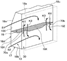
本第2変形例では、上記第1実施形態において、図7に示すように、エバ前ケース部17に、上側通風路13aおよび下側通風路13bの間を空気流が通過する空気通路70a、70bを設ける例について説明する。
(Second modification of the first embodiment)
In the second modification, in the first embodiment, as shown in FIG. 7, an air passage 70 a through which an air flow passes between the upper ventilation path 13 a and the lower ventilation path 13 b, in the front case portion 17, An example in which 70b is provided will be described.

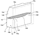
本第2変形例のエバ前ケース部17では、仕切り壁19のうち車幅方向中央部が冷却用熱交換器30側に凸となる凸部19Xが形成されている。これに加えて、仕切り壁19のうち凸部19Xに対して車幅方向一方側および他方側には、凹部19Y、19Zが形成されている。凹部19Y、19Zは、それぞれ、冷却用熱交換器30に対して反対側に凹むように形成されている。このことにより、冷却用熱交換器30の空気流入面31と凹部19Yの間には空気通路70aが形成される。そして、冷却用熱交換器30の空気流入面31と凹部19Zの間には空気通路70bが形成されている。つまり、空気通路70aおよび空気通路70bは、仕切り壁19に対して冷却用熱交換器30の空気流入面31側に形成されている。   In the front case portion 17 of the second modification, a convex portion 19X is formed in which the central portion in the vehicle width direction of the partition wall 19 is convex toward the cooling heat exchanger 30 side. In addition, concave portions 19Y and 19Z are formed on one side and the other side in the vehicle width direction with respect to the convex portion 19X in the partition wall 19. The recesses 19Y and 19Z are formed so as to be recessed on the opposite side with respect to the cooling heat exchanger 30, respectively. Thus, an air passage 70a is formed between the air inflow surface 31 of the cooling heat exchanger 30 and the recess 19Y. An air passage 70b is formed between the air inflow surface 31 of the cooling heat exchanger 30 and the recess 19Z. That is, the air passage 70 a and the air passage 70 b are formed on the air inflow surface 31 side of the cooling heat exchanger 30 with respect to the partition wall 19.

以上のように構成される本第2変形例のエバ前ケース部17には、スクロールケーシング22cの吹出口22dから吸入口13を介して空気流が流れると、この空気流は、仕切り壁19を挟んだ上側通風路13aと下側通風路13bとに分流される。このため、上側通風路13a内の空気流は、主に、図8中矢印S1の如く、冷却用熱交換器30側に流れる。下側通風路13b内の空気流は、主に、図8中矢印S2の如く、冷却用熱交換器30側に流れる。これに加えて、上側通風路13aと下側通風路13bとの間には、空気通路70b、70cを通して空気流が矢印K1、K2、K3、K4の如く流れる。   When an air flow flows through the suction port 13 from the air outlet 22d of the scroll casing 22c, the air flow passes through the partition wall 19 in the front case portion 17 of the second modified example configured as described above. It is divided into the sandwiched upper ventilation path 13a and lower ventilation path 13b. For this reason, the air flow in the upper ventilation path 13a mainly flows toward the cooling heat exchanger 30 as shown by an arrow S1 in FIG. The air flow in the lower ventilation path 13b mainly flows toward the cooling heat exchanger 30 as indicated by an arrow S2 in FIG. In addition, an air flow flows between the upper ventilation path 13a and the lower ventilation path 13b through the air passages 70b and 70c as indicated by arrows K1, K2, K3, and K4.

以上説明した本第2変形例では、仕切り壁19は、ブロアユニット20から吹き出される空気流のうち主流の空気流れ方向に沿うように形成され、かつ空調ケース内を上側通風路13aおよび下側通風路13bに仕切るように設けられている。さらに、このため、冷却用熱交換器30に流れる空気流において、上側通風路13aおよび下側通風路13bが並ぶ上下方向の分布の均一化を図ることができる。   In the second modification described above, the partition wall 19 is formed along the main air flow direction of the air flow blown out from the blower unit 20, and the upper air passage 13a and the lower side are formed in the air conditioning case. It is provided so that it may partition into the ventilation path 13b. Further, for this reason, in the air flow flowing through the cooling heat exchanger 30, the distribution in the vertical direction in which the upper ventilation path 13a and the lower ventilation path 13b are arranged can be made uniform.

さらに、本第2変形例では、仕切り壁19のうち車幅方向中央部に凸部19Xが形成されている。仕切り壁19のうち凸部19Xに対して車幅方向一方側および他方側には、凹部19Y、19Zが形成されている。このため、仕切り壁19のうち車幅方向中央側の奥行き寸法は、仕切り壁19のうち車幅方向一方側および他方側の奥行き寸法に比べて、大きくなる。奥行き寸法とは、対向壁18dと冷却用熱交換器30の空気流入面31とを結ぶ方向(すなわち、車両前後方向)の寸法である。   Furthermore, in the second modified example, a convex portion 19X is formed in the central portion of the partition wall 19 in the vehicle width direction. Concave portions 19Y and 19Z are formed on one side and the other side of the partition wall 19 with respect to the convex portion 19X in the vehicle width direction. For this reason, the depth dimension of the partition wall 19 on the center side in the vehicle width direction is larger than the depth dimension of one side and the other side of the partition wall 19 in the vehicle width direction. The depth dimension is a dimension in a direction connecting the facing wall 18d and the air inflow surface 31 of the cooling heat exchanger 30 (that is, the vehicle longitudinal direction).

ここで、対向壁18dのうち車幅方向中央側は、対向壁18dのうち車幅方向一方側および他方側に比べて、剛性が小さいものの、凸部19X、凹部19Y、19Zを有する仕切り壁19によって、剛性が補強されて、エバ前ケース部17の対向壁18dの剛性の均衡を図ることができる。   Here, the center side in the vehicle width direction of the opposing wall 18d has a smaller rigidity than the one side and the other side in the vehicle width direction of the opposing wall 18d, but the partition wall 19 having the convex portions 19X and the concave portions 19Y and 19Z. Thus, the rigidity is reinforced and the rigidity of the opposing wall 18d of the front case portion 17 can be balanced.

(第2実施形態)
上記第1実施形態では、1つの板材によって仕切り壁19を構成した例について説明したが、これに代えて、本実施形態では、複数の板材によって仕切り壁19を構成した例について説明する。
(Second Embodiment)
Although the said 1st Embodiment demonstrated the example which comprised the partition wall 19 with one board | plate material, it replaces with this and this embodiment demonstrates the example which comprised the partition wall 19 with the several board | plate material.

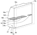
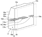
図9は本実施形態のエバ前ケース部17の内部を示す透視図である。本実施形態の仕切り壁19は、それぞれ、3つの板部材19a、19b、19cによって構成されている。板部材19a、19b、19cは、ブロアユニット20から吹き出される空気流のうち主流の流れ方向に沿うようにそれぞれ板状に形成されているものである。板部材19a、19b、19cは、水平方向に平行に配置されたもので、水平方向に並べられている。   FIG. 9 is a perspective view showing the inside of the front case portion 17 of the present embodiment. The partition wall 19 of this embodiment is comprised by the three plate members 19a, 19b, and 19c, respectively. The plate members 19a, 19b, and 19c are each formed in a plate shape so as to follow the mainstream flow direction in the air flow blown out from the blower unit 20. The plate members 19a, 19b, and 19c are arranged in parallel in the horizontal direction, and are arranged in the horizontal direction.

本実施形態では、板部材19a、19b、19cは、それぞれ、ブロアユニット20から吹き出される空気流のうち主流の流れ方向に沿って並ぶように、それぞれ間隔を開けて配置されている。すなわち、板部材19a、19b、19cは、それぞれ、間隔を開けて、主流の流れ方向に平行に配置されている。   In the present embodiment, the plate members 19a, 19b, and 19c are arranged at intervals so as to be aligned along the mainstream flow direction in the airflow blown from the blower unit 20, respectively. That is, the plate members 19a, 19b, and 19c are arranged in parallel with the mainstream flow direction at intervals.

したがって、本実施形態によれば、上記第1実施形態と同様、仕切り壁19によって、エバ前ケース部17の対向壁18dの剛性を大きくすることができる。このため、エバ前ケース部17に単層流用電動送風機22から伝わる振動で共振することを抑制することができる。   Therefore, according to this embodiment, the rigidity of the opposing wall 18d of the front case part 17 can be increased by the partition wall 19 as in the first embodiment. For this reason, it can suppress that it resonates with the vibration transmitted from the electric blower 22 for single laminar flow to the front case part 17 in the ever.

本実施形態の板部材19a、19bの間には、間隔が開けてある。板部材19b、19cの間には間隔を開けてある。このため、板部材19a、19bの間の間隔、および板部材19b、19cの間の間隔を通して上側通風路13aおよび下側通風路13bの間に空気流が流れる。このため、冷却用熱交換器30に流れる空気流において、上側通風路13aおよび下側通風路13bが並ぶ上下方向の分布の均一化をより一層向上させることができる。   A space is provided between the plate members 19a and 19b of the present embodiment. There is a gap between the plate members 19b and 19c. For this reason, an airflow flows between the upper ventilation path 13a and the lower ventilation path 13b through the interval between the plate members 19a and 19b and the interval between the plate members 19b and 19c. For this reason, in the airflow flowing through the cooling heat exchanger 30, it is possible to further improve the uniform distribution in the vertical direction in which the upper ventilation path 13a and the lower ventilation path 13b are arranged.

本実施形態のエバ前ケース部17には、空気通路70a、70bを設けられていない。   Air passages 70a and 70b are not provided in the pre-evacuation case portion 17 of the present embodiment.

(第2実施形態の第1変形例)
本第1変形例では、エバ前ケース部17に空気通路70a、70bを設けないようにした例について説明したが、図10に示すように、エバ前ケース部17に空気通路70a、70bを設けてもよい。
(First Modification of Second Embodiment)
In the first modification, the example in which the air passages 70a and 70b are not provided in the front case portion 17 has been described. However, as shown in FIG. 10, the air passages 70a and 70b are provided in the front case portion 17. May be.

本第1変形例の板部材19a、19b、19cは、図10に示すように、互いに間隔を開けて、車幅方向に並べられている。板部材19aに対して冷却用熱交換器30側には、空気通路70aが形成されている。板部材19cに対して冷却用熱交換器30側には、空気通路70bが形成されている。   As shown in FIG. 10, the plate members 19a, 19b, and 19c of the first modification are arranged in the vehicle width direction at intervals. An air passage 70a is formed on the cooling heat exchanger 30 side with respect to the plate member 19a. An air passage 70b is formed on the cooling heat exchanger 30 side with respect to the plate member 19c.

本第1変形例では、板部材19bの奥行き寸法は、板部材19a、19cの奥行き寸法に比べて大きくなっている。このため、板部材19bは、その板面方向の大きさが、板部材19a、19cの板面方向の大きさに比べて大きくなっている。奥行き寸法とは、上述の如く、対向壁18dと冷却用熱交換器30の空気流入面31とを結ぶ方向(すなわち、車両前後方向)の寸法である。板面方向とは、板部材19a、19c、19bが拡がる方向のことである面方向のことである。   In the first modification, the depth dimension of the plate member 19b is larger than the depth dimension of the plate members 19a and 19c. For this reason, the size of the plate member 19b in the plate surface direction is larger than the size of the plate members 19a and 19c in the plate surface direction. As described above, the depth dimension is a dimension in the direction connecting the facing wall 18d and the air inflow surface 31 of the cooling heat exchanger 30 (that is, the vehicle longitudinal direction). The plate surface direction is a surface direction that is a direction in which the plate members 19a, 19c, and 19b expand.

ここで、板部材19bは、エバ前ケース部17の対向壁18dのうち車幅方向中央側に支持されている。板部材19a、19cは、エバ前ケース部17の対向壁18dのうち車幅方向一方側および他方側に支持されている。対向壁18dのうち車幅方向中央側は、対向壁18dのうち車幅方向一方側および他方側に比べて、剛性が小さい。   Here, the plate member 19b is supported on the center side in the vehicle width direction of the opposing wall 18d of the front case portion 17. The plate members 19a and 19c are supported on one side and the other side of the opposite wall 18d of the front case portion 17 in the vehicle width direction. The center side in the vehicle width direction of the facing wall 18d is less rigid than the one side and the other side in the vehicle width direction of the facing wall 18d.

これに対して、本第1変形例では、板部材19bの板面方向の大きさは、上述の如く、板部材19a、19cの板面方向の大きさに比べて大きくなっている。このため、対向壁18dのうち車幅方向中央側の変位がより一層抑えられる。これにより、対向壁18dのうち車幅方向中央側の剛性を補強することができる。したがって、エバ前ケース部17の対向壁18dの剛性の均衡を図ることができる。   On the other hand, in the first modification, the size of the plate member 19b in the plate surface direction is larger than the size of the plate members 19a and 19c in the plate surface direction as described above. For this reason, the displacement of the opposite side wall 18d on the center side in the vehicle width direction is further suppressed. Thereby, the rigidity of the center side in the vehicle width direction of the opposing wall 18d can be reinforced. Therefore, the rigidity of the opposing wall 18d of the front case portion 17 can be balanced.

(第3実施形態)
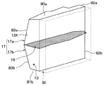
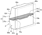
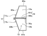
本第3実施形態では、上記第1実施形態のエバ前ケース部17を2つの分割ケース部を組み合わせて構成した例について説明する。図11は本実施形態のエバ前ケース部17の内部を示す透視図である。
(Third embodiment)
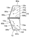
In the third embodiment, an example will be described in which the pre-evacuation case portion 17 of the first embodiment is configured by combining two divided case portions. FIG. 11 is a perspective view showing the inside of the front case portion 17 of the present embodiment.

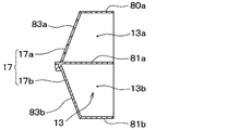
本実施形態のエバ前ケース部17は、上側分割ケース部17aと下側分割ケース部17bとを組み合わせて構成されている。上側分割ケース部17aは、下側分割ケース部17bに対して天地方向上側に配置されている。   The pre-evaporation case portion 17 of the present embodiment is configured by combining an upper divided case portion 17a and a lower divided case portion 17b. The upper division | segmentation case part 17a is arrange | positioned with respect to the lower division | segmentation case part 17b at the heaven district improvement side.

上側分割ケース部17aは、上壁80a、下壁81a、側壁82a、および対向壁83aによって上側通風路13aを構成している。下側分割ケース部17bは、下壁81b、側壁82b、および対向壁83bによって下側通風路13bを構成している。   The upper divided case portion 17a constitutes the upper ventilation path 13a by the upper wall 80a, the lower wall 81a, the side wall 82a, and the opposing wall 83a. In the lower divided case portion 17b, the lower ventilation path 13b is configured by the lower wall 81b, the side wall 82b, and the opposing wall 83b.

ここで、上壁80bは、上記第1実施形態の上壁18aに対応し、下壁81bは、上記第1実施形態の下壁18bに対応し、対向壁83a、83bは、上記第1実施形態の側壁18cに対応している。対向壁83a、83bは、それぞれ、上記第1実施形態の対向壁18dに対応するもので、空気流れ上流側から下流側に向かうほど冷却用熱交換器30の空気流入面31側に近づくように階段状に形成されている。   Here, the upper wall 80b corresponds to the upper wall 18a of the first embodiment, the lower wall 81b corresponds to the lower wall 18b of the first embodiment, and the opposing walls 83a and 83b correspond to the first embodiment. It corresponds to the side wall 18c of the form. The facing walls 83a and 83b correspond to the facing wall 18d of the first embodiment, respectively, and approach the air inflow surface 31 side of the cooling heat exchanger 30 from the upstream side to the downstream side of the air flow. It is formed in steps.

対向壁83aは、上壁80a側から下壁81a側に近づくほど冷却用熱交換器30から遠ざかるように傾斜している。対向壁83bは、下壁81b側から上壁80b側に近づくほど冷却用熱交換器30から遠ざかるように傾斜している。   The facing wall 83a is inclined so as to move away from the cooling heat exchanger 30 as it approaches the lower wall 81a side from the upper wall 80a side. The opposing wall 83b is inclined so as to move away from the cooling heat exchanger 30 as it approaches the upper wall 80b side from the lower wall 81b side.

さらに、上側分割ケース部17aの下壁81aは、上記第実施形態の仕切り壁19を構成するものであって、主流の流れ方向に沿うように板状に形成されている。下壁81aは、上側分割ケース部17aのうち下側分割ケース部17b側に配置されている。下壁81aと冷却用熱交換器30の空気流入面31との間には、空気通路70a、70bが形成されていない。   Further, the lower wall 81a of the upper divided case portion 17a constitutes the partition wall 19 of the above-described embodiment, and is formed in a plate shape along the mainstream flow direction. The lower wall 81a is disposed on the lower divided case portion 17b side of the upper divided case portion 17a. Air passages 70 a and 70 b are not formed between the lower wall 81 a and the air inflow surface 31 of the cooling heat exchanger 30.

以上説明した本実施形態によれば、上側分割ケース部17aの下壁81aは、上記第1実施形態と同様に、上側通風路13aと下側通風路13bとを仕切る仕切り壁を構成している。このため、対向壁83a、83bのうち下壁81aを支持している部位の変位が抑制されることにより、上記第1実施形態と同様に、対向壁83a、83bの剛性を大きくすることができる。   According to the present embodiment described above, the lower wall 81a of the upper divided case portion 17a constitutes a partition wall that partitions the upper ventilation path 13a and the lower ventilation path 13b, as in the first embodiment. . For this reason, the rigidity of the opposing walls 83a and 83b can be increased similarly to the first embodiment by suppressing the displacement of the part of the opposing walls 83a and 83b that supports the lower wall 81a. .

(第3実施形態の第1変形例)
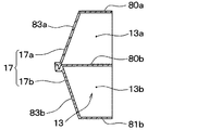
上記第3実施形態では、上側分割ケース部17aの下壁81aにより、上側通風路13aと下側通風路13bとを仕切る仕切り壁を構成した例について説明したが、これに代えて、図13に示すように、下側分割ケース部17bの上壁80bによって上側通風路13aと下側通風路13bとを仕切る仕切り壁を構成してもよい。
(First Modification of Third Embodiment)
In the said 3rd Embodiment, although the partition wall which partitions off the upper side ventilation path 13a and the lower side ventilation path 13b by the lower wall 81a of the upper side division | segmentation case part 17a was demonstrated, instead of this, FIG. As shown, a partition wall that partitions the upper ventilation path 13a and the lower ventilation path 13b by the upper wall 80b of the lower divided case portion 17b may be configured.

本第1変形例の下側分割ケース部17bは、上壁80b、下壁81b、側壁82b、および対向壁83bによって下側通風路13bを構成している。上壁80bは、下側分割ケース部17bのうち上側分割ケース部17a側に配置されている。   In the lower divided case portion 17b of the first modification, the lower ventilation path 13b is configured by the upper wall 80b, the lower wall 81b, the side wall 82b, and the opposing wall 83b. The upper wall 80b is disposed on the upper divided case portion 17a side of the lower divided case portion 17b.

以上説明した本実施形態によれば、対向壁83bは、上壁80bを支持している。上壁80bは、上側通風路13aと下側通風路13bとを仕切る仕切り壁を構成している。このため、対向壁83a、83bのうち上壁80bを支持している部位の変位が抑制されることにより、対向壁83a、83bの剛性を大きくすることができる。   According to the present embodiment described above, the opposing wall 83b supports the upper wall 80b. The upper wall 80b constitutes a partition wall that partitions the upper ventilation path 13a and the lower ventilation path 13b. For this reason, the rigidity of the opposing walls 83a and 83b can be increased by suppressing the displacement of the portion of the opposing walls 83a and 83b that supports the upper wall 80b.

(第3実施形態の第2変形例)
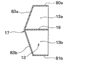
上記第3実施形態、およびその上記第1変形例では、上側分割ケース部17aと下側分割ケース部17bとを組み合わせてエバ前ケース部17を構成した例について説明したが、これに代えて、図14に示すように、上壁80a、側壁82a、82b、下壁81b、対向壁83a、83b、および仕切り壁19を一体に成形したものをエバ前ケース部17として用いてもよい。すなわち、仕切り壁19は、エバ前ケース部17に一体に成形されている。
(Second Modification of Third Embodiment)
In the said 3rd Embodiment and the said 1st modification, although the example which comprised the front case part 17 combining the upper side division | segmentation case part 17a and the lower side division | segmentation case part 17b was demonstrated, it replaced with this, As shown in FIG. 14, the front case portion 17 may be formed by integrally forming the upper wall 80 a, the side walls 82 a and 82 b, the lower wall 81 b, the opposing walls 83 a and 83 b, and the partition wall 19. In other words, the partition wall 19 is formed integrally with the front case portion 17.

(第3実施形態の第3変形例)
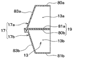
本第3変形例では、図15、図16に示すように、上記第3実施形態と第3実施形態の第1変形例とを組み合わせて、上側分割ケース部17aの下壁81aと下側分割ケース部17bの上壁80bによって、上側通風路13aと下側通風路13bとを仕切る仕切り壁19を構成してもよい。
(Third Modification of Third Embodiment)
In the third modification, as shown in FIGS. 15 and 16, the lower wall 81a and the lower partition are divided by combining the third embodiment and the first modification of the third embodiment. You may comprise the partition wall 19 which partitions off the upper side ventilation path 13a and the lower side ventilation path 13b with the upper wall 80b of the case part 17b.

上側分割ケース部17aは、上壁80a、下壁81a、側壁82a、および対向壁83aによって上側通風路13aを構成している。下側分割ケース部17bは、上壁80b、下壁81b、側壁82b、および対向壁83bによって下側通風路13bを構成している。上側分割ケース部17aの下壁81aは、下側分割ケース部17b側に配置されている。下壁81aは、対向壁83aによって支持されている。下側分割ケース部17bの上壁80bは、上側分割ケース部17a側に配置されている。上壁80bは、対向壁83bによって支持されている。   The upper divided case portion 17a constitutes the upper ventilation path 13a by the upper wall 80a, the lower wall 81a, the side wall 82a, and the opposing wall 83a. The lower divided case portion 17b constitutes the lower ventilation path 13b by the upper wall 80b, the lower wall 81b, the side wall 82b, and the opposing wall 83b. The lower wall 81a of the upper divided case portion 17a is disposed on the lower divided case portion 17b side. The lower wall 81a is supported by the opposing wall 83a. The upper wall 80b of the lower divided case portion 17b is disposed on the upper divided case portion 17a side. The upper wall 80b is supported by the opposing wall 83b.

上側分割ケース部17aの下壁81aおよび下側分割ケース部17bの上壁80bは、互いに厚み方向に隣り合うように上下に配置されて、仕切り壁19を構成している。つまり、下壁81aおよび上壁80bは、隣接して配置されて、仕切り壁19を構成している。下壁81aおよび上壁80bは、主流の空気流れ方向に沿うように形成されている。   The lower wall 81a of the upper divided case portion 17a and the upper wall 80b of the lower divided case portion 17b are arranged vertically so as to be adjacent to each other in the thickness direction, thereby constituting the partition wall 19. That is, the lower wall 81a and the upper wall 80b are arranged adjacent to each other to form the partition wall 19. The lower wall 81a and the upper wall 80b are formed along the mainstream air flow direction.

以上説明した本実施形態によれば、対向壁83aが下壁81aを支持している。対向壁83bが上壁80b支持している。下壁81aおよび上壁80bが仕切り壁19を構成している。このため、対向壁83a、83bのうち仕切り壁19を支持している部位の変位が抑制されることにより、対向壁83a、83bの剛性を大きくすることができる。   According to this embodiment described above, the opposing wall 83a supports the lower wall 81a. The opposing wall 83b supports the upper wall 80b. The lower wall 81a and the upper wall 80b constitute the partition wall 19. For this reason, the rigidity of the opposing walls 83a and 83b can be increased by suppressing the displacement of the part of the opposing walls 83a and 83b that supports the partition wall 19.

(第3実施形態の第4変形例)
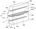
本第4変形例では、上記第3実施形態の第3変形例において、図17、図18に示すように、下壁81aおよび上壁80bと冷却用熱交換器30の空気流入面31との間に、上記第1実施形態の第2変形例と同様に、空気通路70a、70bを形成してもよい。このため、上記第1実施形態の第2変形例と同様の効果が得られる。
(Fourth modification of the third embodiment)
In the fourth modification example, in the third modification example of the third embodiment, as shown in FIGS. 17 and 18, the lower wall 81 a and the upper wall 80 b and the air inflow surface 31 of the cooling heat exchanger 30. In the middle, air passages 70a and 70b may be formed in the same manner as in the second modification of the first embodiment. For this reason, the effect similar to the 2nd modification of the said 1st Embodiment is acquired.

(第4実施形態)
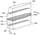
本実施形態では、上記第3実施形態のエバ前ケース部17において、2つの仕切り壁を追加した例について説明する。図19は本実施形態のエバ前ケース部17の内部を示す透視図である。
(Fourth embodiment)
In the present embodiment, an example in which two partition walls are added in the pre-evacuation case portion 17 of the third embodiment will be described. FIG. 19 is a perspective view showing the inside of the front case portion 17 of the present embodiment.

本実施形態のエバ前ケース部17には、図16のエバ前ケース部17に対して仕切り壁84a、84bが追加されている。仕切り壁84aは、上側分割ケース部17a内に配置されている。仕切り壁84bは、下側分割ケース部17b内に配置されている。仕切り壁84a、84bは、それぞれ、水平方向に平行に形成された板状に形成されている。このため、仕切り壁84a、84bは、仕切り壁19と同様に、主流の空気流れ方向に沿うように形成されている。つまり、仕切り壁19、84a、84bは、ブロアユニット20から吹き出される空気流のうち主流の流れ方向から視て互いに重なり合わないように配置されている。このことにより、仕切り壁19、84a、84bは、主流の流れ方向に直交する方向に並べられている。   Partition walls 84a and 84b are added to the pre-evacuation case portion 17 of the present embodiment with respect to the pre-evacuation case portion 17 of FIG. The partition wall 84a is arrange | positioned in the upper side division | segmentation case part 17a. The partition wall 84b is disposed in the lower split case portion 17b. Each of the partition walls 84a and 84b is formed in a plate shape formed in parallel to the horizontal direction. For this reason, the partition walls 84 a and 84 b are formed along the mainstream air flow direction in the same manner as the partition wall 19. That is, the partition walls 19, 84 a, 84 b are arranged so as not to overlap each other when viewed from the mainstream flow direction in the air flow blown out from the blower unit 20. Thus, the partition walls 19, 84a, 84b are arranged in a direction orthogonal to the mainstream flow direction.

仕切り壁84aは、上側分割ケース部17a内を上側通風路13cと下側通風路13dとに仕切る。仕切り壁84aは、側壁82aおよび対向壁83aによって支持されている。仕切り壁84aと冷却用熱交換器30の空気流入面31との間には、空気通路71a(図20参照)が設けられている。空気通路71aは、上側分割ケース部17a内の上側通風路13cおよび下側通風路13dの間に空気を通過させる。   The partition wall 84a partitions the inside of the upper divided case portion 17a into an upper ventilation path 13c and a lower ventilation path 13d. The partition wall 84a is supported by the side wall 82a and the opposing wall 83a. An air passage 71a (see FIG. 20) is provided between the partition wall 84a and the air inflow surface 31 of the cooling heat exchanger 30. The air passage 71a allows air to pass between the upper ventilation path 13c and the lower ventilation path 13d in the upper divided case portion 17a.

仕切り壁84bは、下側分割ケース部17b内を上側通風路13eと下側通風路13fとに仕切る。仕切り壁84bは、側壁82bおよび対向壁83bによって支持されている。仕切り壁84bと冷却用熱交換器30の空気流入面31との間には、空気通路71b(図10参照)が設けられている。空気通路71bは、下側分割ケース部17b内の上側通風路13eおよび下側通風路13fの間に空気を通過させる。   The partition wall 84b partitions the lower divided case portion 17b into an upper ventilation path 13e and a lower ventilation path 13f. The partition wall 84b is supported by the side wall 82b and the opposing wall 83b. An air passage 71b (see FIG. 10) is provided between the partition wall 84b and the air inflow surface 31 of the cooling heat exchanger 30. The air passage 71b allows air to pass between the upper ventilation path 13e and the lower ventilation path 13f in the lower divided case portion 17b.

以上説明した本実施形態によれば、上側分割ケース部17aの対向壁83aは、仕切り壁84aを支持している。このため、対向壁83aのうち仕切り壁84aを支持する部位の変位を抑制することにより、対向壁83aの剛性を大きくすることができる。これに加えて、仕切り壁84aは、側壁82aにより支持されている。よって、対向壁83aの剛性を大きくすることができる。   According to this embodiment described above, the facing wall 83a of the upper divided case portion 17a supports the partition wall 84a. For this reason, the rigidity of the opposing wall 83a can be increased by suppressing the displacement of the part of the opposing wall 83a that supports the partition wall 84a. In addition, the partition wall 84a is supported by the side wall 82a. Therefore, the rigidity of the opposing wall 83a can be increased.

下側分割ケース部17bの対向壁83bは、仕切り壁84bを支持している。このため、対向壁83bのうち仕切り壁84bを支持する部位の変位を抑えることにより、対向壁83bの剛性を大きくすることができる。これに加えて、仕切り壁84bは、側壁82bによって支持されている。   The facing wall 83b of the lower divided case portion 17b supports the partition wall 84b. For this reason, the rigidity of the opposing wall 83b can be increased by suppressing the displacement of the portion of the opposing wall 83b that supports the partition wall 84b. In addition, the partition wall 84b is supported by the side wall 82b.

以上により、エバ前ケース部17の対向壁(83a、83b)の剛性をより一層大きくすることができる。したがって、単層流用電動送風機22から伝わる振動で対向壁83a、83bが共振することをより確実に抑制することができる。   As described above, the rigidity of the opposing walls (83a, 83b) of the front case portion 17 can be further increased. Therefore, it can suppress more reliably that the opposing walls 83a and 83b resonate with the vibration transmitted from the electric blower 22 for single layer flows.

本実施形態の仕切り壁84a、84bは、主流の空気流れに沿うように板状に形成されている。仕切り壁84aと冷却用熱交換器30との間には、空気通路71aが設けられている。このため、上側分割ケース部17aにおいて空気通路85aを通過して上側通風路13cおよび下側通風路13dの間を空気流を通過させることができる。   The partition walls 84a and 84b of the present embodiment are formed in a plate shape so as to follow the mainstream air flow. An air passage 71 a is provided between the partition wall 84 a and the cooling heat exchanger 30. For this reason, it is possible to pass the air flow between the upper ventilation path 13c and the lower ventilation path 13d through the air passage 85a in the upper divided case portion 17a.

さらに、仕切り壁84bと冷却用熱交換器30との間には、空気通路71bが設けられている。このため、下側分割ケース部17bにおいて空気通路71bを通して上側通風路13eおよび下側通風路13fの間を空気流を通過させることができる。   Further, an air passage 71 b is provided between the partition wall 84 b and the cooling heat exchanger 30. For this reason, an air flow can be allowed to pass between the upper ventilation path 13e and the lower ventilation path 13f through the air passage 71b in the lower divided case portion 17b.

以上により、冷却用熱交換器30に流れる空気流において、上下方向の分布の均一化を図ることができる。   As described above, the distribution in the vertical direction can be made uniform in the airflow flowing through the cooling heat exchanger 30.

(第4実施形態の第1変形例)
本第1変形例では、上記第4実施形態において、図21、図22に示すように、上側通風路13aおよび下側通風路13bの間を空気流が通過する空気通路70a、70bを設けてもよい。この場合、上記第1実施形態の第2変形例と同様の効果が得られる。
(First Modification of Fourth Embodiment)
In the first modification, in the fourth embodiment, as shown in FIGS. 21 and 22, air passages 70a and 70b through which an air flow passes between the upper ventilation passage 13a and the lower ventilation passage 13b are provided. Also good. In this case, the same effect as the second modification of the first embodiment can be obtained.

(他の実施形態)
(1)上記第1〜4の実施形態、および各変形例では、仕切り壁19を水平方向に平行になるように配置したが、これに代えて、仕切り壁19を水平方向に直交するように配置してもよい。
(Other embodiments)
(1) In the first to fourth embodiments and the modifications, the partition wall 19 is arranged so as to be parallel to the horizontal direction. Instead, the partition wall 19 is orthogonal to the horizontal direction. You may arrange.

(2)上記第4の実施形態、およびその第1変形例では、仕切り壁19、84a、84bを水平方向に平行になるように配置したが、これに代えて、仕切り壁19、84a、84bを水平方向に直交するように配置してもよい。   (2) In the fourth embodiment and the first modification thereof, the partition walls 19, 84a, 84b are arranged so as to be parallel to the horizontal direction, but instead, the partition walls 19, 84a, 84b are arranged. May be arranged so as to be orthogonal to the horizontal direction.

(3)上記第1〜4の実施形態、および各変形例では、本発明のファン22bとしては、遠心式ファンを用いた例について説明したが、これに代えて、遠心式ファン以外のタイプのファンを本発明のファン22bとして用いてもよい。   (3) In the first to fourth embodiments and the modifications described above, the example using the centrifugal fan has been described as the fan 22b of the present invention, but instead of this, a type other than the centrifugal fan is used. A fan may be used as the fan 22b of the present invention.

(4)上記第1〜4の実施形態、および各変形例では、本発明のファン22bを駆動するモータとして、直流モータ22aを用いた例について説明したが、これに代えて、直流モータ22a以外のタイプのモータを、本発明のファン22bを駆動するモータとして用いてもよい。   (4) In the first to fourth embodiments and the modifications described above, the example in which the DC motor 22a is used as the motor for driving the fan 22b of the present invention has been described, but instead of this, other than the DC motor 22a. This type of motor may be used as a motor for driving the fan 22b of the present invention.

(5)上記第1〜4の実施形態、および各変形例では、スクロールケーシング22cおよびダクト23から本発明の送風ケースを構成した例について説明したが、これに代えて、スクロールケーシング22cおよびダクト23のうちスクロールケーシング22cによって本発明の送風ケースを構成してもよい。つまり、スクロールケーシング22cをエバ前ケース部17に直接接続してもよい。   (5) In the first to fourth embodiments and the modifications, the example in which the air blowing case of the present invention is configured from the scroll casing 22c and the duct 23 has been described, but instead the scroll casing 22c and the duct 23 are described. Among them, the scroll casing 22c may constitute the blower case of the present invention. That is, the scroll casing 22c may be directly connected to the pre-evaluation case portion 17.

(6)上記第1〜4の実施形態、および各変形例では、本発明の仕切り壁(19、84a、84b)をエバ前ケース部17のうち対向壁18dによって支持した例について説明したが、これに代えて、エバ前ケース部17の上壁18a、下壁18b、側壁18cのうちいずれかによって、本発明の仕切り壁を支持すればよい。   (6) In the first to fourth embodiments and the modifications, the examples in which the partition wall (19, 84a, 84b) of the present invention is supported by the opposing wall 18d in the front case portion 17 have been described. Instead of this, the partition wall of the present invention may be supported by any one of the upper wall 18a, the lower wall 18b, and the side wall 18c of the front case portion 17.

(7)上記第2実施形態の第1変形例では、板部材19bの板面方向の大きさを板部材19a、19cの板面方向の大きさに比べて大きくして、対向壁18dのうち車幅方向中央側の剛性を補強した例について説明したが、これに代えて、次のようにしてもよい。すなわち、板部材19bの厚み寸法を板部材19a、19cの厚み寸法に比べて大きくして、対向壁18dのうち車幅方向中央側の剛性を補強してもよい。   (7) In the first modification of the second embodiment, the size of the plate member 19b in the plate surface direction is made larger than the size of the plate members 19a and 19c in the plate surface direction, The example in which the rigidity in the center in the vehicle width direction is reinforced has been described, but the following may be used instead. That is, the thickness dimension of the plate member 19b may be made larger than the thickness dimension of the plate members 19a and 19c to reinforce the rigidity on the center side in the vehicle width direction of the opposing wall 18d.

なお、本発明は上記した実施形態に限定されるものではなく、特許請求の範囲に記載した範囲内において適宜変更が可能である。また、上記第1〜第4の実施形態は、互いに無関係なものではなく、組み合わせが明らかに不可な場合を除き、適宜組み合わせが可能である。また、上記第1〜第4の実施形態において、構成要素等の形状、位置関係等に言及するときは、特に明示した場合および原理的に特定の形状、位置関係等に限定される場合等を除き、その形状、位置関係等に限定されるものではない。   In addition, this invention is not limited to above-described embodiment, In the range described in the claim, it can change suitably. Further, the first to fourth embodiments are not irrelevant to each other and can be appropriately combined except when the combination is clearly impossible. Further, in the first to fourth embodiments, when referring to the shape, positional relationship, etc. of the constituent elements, etc., the case where it is clearly specified and the case where it is limited to a specific shape, positional relationship, etc. in principle, etc. Except, it is not limited to the shape, positional relationship, and the like.

1 車両用空調装置
10 室内空調ユニット
17 エバ前ケース部
19、84a、84b 仕切り壁
20 ブロアユニット
70a、70b、71a、71b 空気通路
22 電動送風機
22a 直流モータ
22b ファン
22c スクロールケーシング
30 冷却用熱交換器
DESCRIPTION OF SYMBOLS 1 Vehicle air conditioner 10 Indoor air-conditioning unit 17 Evacuation case part 19, 84a, 84b Partition wall 20 Blower unit 70a, 70b, 71a, 71b Air passage 22 Electric blower 22a DC motor 22b Fan 22c Scroll casing 30 Cooling heat exchanger

Claims (15)

電動モータ(22a)と、前記電動モータにより駆動されて車室外空気および車室内空気のうち少なくとも一方を導入して吹き出すファン(22b)と、前記ファンから吹き出される前記車室外空気および前記車室内空気を分け隔てなく流通させる単層の空気流路を構成する送風ケース(22c)と、を備える単層流用電動送風機(22)と、
前記送風ケースから吹き出される空気流を車室内に向けて流通させる空調ケース(11)と、
前記空調ケース内に配置されて、前記送風ケースから吹き出される空気流を冷却する冷却用熱交換器(30)と、
前記空調ケース内のうち前記冷却用熱交換器に対して空気流れ上流側に配置され、前記空調ケース内を第1、第2の通風路(13a、13b、13c、13d、13e、13f)に仕切る仕切り壁(19、84a、84b)と、を備え、
前記第1、第2の通風路には、前記送風ケースから吹き出される空気流が流れるようになっており、
前記空調ケースのうち前記冷却用熱交換器に対して空気流れ上流側の部位(17)には前記送風ケースが接続され、
前記仕切り壁は、前記空調ケースのうち前記冷却用熱交換器に対して空気流れ上流側の部位(17)によって支持されるものであって、前記送風ケースから吹き出される空気流のうち主流の空気流れ方向(S1、S2)に沿うように形成されていることを特徴とする車両用空調装置。
An electric motor (22a); a fan (22b) driven by the electric motor to introduce and blow out at least one of vehicle exterior air and vehicle interior air; and vehicle exterior air and vehicle interior blown from the fan A single-layer flow electric blower (22) comprising a blower case (22c) that constitutes a single-layer air flow path through which air flows without being separated;
An air-conditioning case (11) for distributing an air flow blown out of the blower case toward the vehicle interior;
A cooling heat exchanger (30) disposed in the air conditioning case for cooling an air flow blown from the air blowing case;
It arrange | positions in the air flow upstream with respect to the said heat exchanger for cooling among the said air-conditioning cases, and the said air-conditioning case is made into the 1st, 2nd ventilation path (13a, 13b, 13c, 13d, 13e, 13f). Partition walls (19, 84a, 84b) for partitioning,
In the first and second ventilation paths, an air flow blown out from the blower case flows,
The air blowing case is connected to a portion (17) on the upstream side of the air flow with respect to the cooling heat exchanger in the air conditioning case,
The partition wall is supported by a portion (17) on the upstream side of the air flow with respect to the cooling heat exchanger in the air conditioning case, and is a mainstream of the air flow blown out of the air blowing case. An air conditioner for a vehicle characterized by being formed along an air flow direction (S1, S2).
前記仕切り壁は、前記空調ケース内のうち前記冷却用熱交換器に対して空気流れ上流側の部位(17)に一体形成されたものであることを特徴とする請求項1に記載の車両用空調装置。   2. The vehicle according to claim 1, wherein the partition wall is integrally formed in a portion (17) upstream of the air flow with respect to the cooling heat exchanger in the air conditioning case. Air conditioner. 前記空調ケース内のうち前記冷却用熱交換器に対して空気流れ上流側の部位(17)は、前記第1の通風路を形成する第1分割ケース部(17a)と、前記第2の通風路を形成する第2分割ケース部(17b)とを組み合わせて構成されていることを特徴とする請求項1に記載の車両用空調装置。   A portion (17) on the upstream side of the air flow with respect to the cooling heat exchanger in the air conditioning case includes a first divided case portion (17a) that forms the first ventilation passage, and the second ventilation passage. The vehicle air conditioner according to claim 1, wherein the vehicle air conditioner is configured by combining with a second divided case portion (17b) that forms a road. 前記第1分割ケース部のうち前記第2分割ケース部側には、第1の壁(81a)が設けられており、
前記第2分割ケース部のうち前記第1分割ケース部側には、第2の壁(80b)が設けられており、
前記第1、第2の壁は、隣接して配置されて前記仕切り壁を構成することを特徴とする請求項3に記載の車両用空調装置。
A first wall (81a) is provided on the second divided case portion side of the first divided case portion,
A second wall (80b) is provided on the first divided case portion side of the second divided case portion,
The vehicle air conditioner according to claim 3, wherein the first and second walls are arranged adjacent to each other to constitute the partition wall.
前記第1分割ケース部のうち前記第2分割ケース部側には、前記仕切り壁を構成する第1の壁(81a)が設けられていることを特徴とする請求項3に記載の車両用空調装置。   4. The vehicle air conditioner according to claim 3, wherein a first wall (81 a) that constitutes the partition wall is provided on the second divided case portion side of the first divided case portion. 5. apparatus. 前記第2分割ケース部のうち前記第1分割ケース部側には、前記仕切り壁を構成する第2の壁(80b)が設けられていることを特徴とする請求項3に記載の車両用空調装置。   The vehicle air conditioner according to claim 3, wherein a second wall (80b) constituting the partition wall is provided on the first divided case portion side of the second divided case portion. apparatus. 前記第1分割ケース部は、前記第2分割ケース部に対して上側に配置されていることを特徴とする請求項3に記載の車両用空調装置。   The vehicle air conditioner according to claim 3, wherein the first divided case portion is disposed on an upper side with respect to the second divided case portion. 前記仕切り壁(19、84a、84b)が複数設けられており、
前記複数の仕切り壁が、前記空気流れ方向から視たときに互いに重なり合わないように配置されていることを特徴とする請求項1ないし7のいずれか1つに記載の車両用空調装置。
A plurality of the partition walls (19, 84a, 84b) are provided,
The vehicle air conditioner according to any one of claims 1 to 7, wherein the plurality of partition walls are arranged so as not to overlap each other when viewed from the air flow direction.
前記複数の仕切り壁が、それぞれ、上下方向に並べられていることを特徴とする請求項8に記載の車両用空調装置。   The vehicle air conditioner according to claim 8, wherein the plurality of partition walls are arranged in a vertical direction. 前記仕切り壁は、前記主流の流れ方向に沿うようにそれぞれ板状に形成されている複数の板部材(19a、19b、19c)から構成されており、
前記複数の板部材は、前記空気流れ方向に沿って並ぶように、それぞれ、間隔をあけて配置されていることを特徴とする請求項1ないし9のいずれか1つに記載の車両用空調装置。
The partition wall is composed of a plurality of plate members (19a, 19b, 19c) each formed in a plate shape along the mainstream flow direction,
The vehicle air conditioner according to any one of claims 1 to 9, wherein the plurality of plate members are arranged at intervals so as to be aligned along the air flow direction. .
前記複数の板部材のうち前記空調ケースの剛性が小さい部分に支持される板部材(19b)は、前記複数の板部材のうち前記空調ケースの剛性が大きい部分に支持される板部材(19a、19c)に比べて、板面方向の大きさが大きくなっていることを特徴とする請求項10に記載の車両用空調装置。   A plate member (19b) supported by a portion of the plurality of plate members having a low rigidity of the air conditioning case is a plate member (19a) supported by a portion of the plurality of plate members having a high rigidity of the air conditioning case. The vehicle air conditioner according to claim 10, wherein the size in the plate surface direction is larger than that of 19c). 前記空調ケースのうち前記冷却用熱交換器に対して空気流れ上流側の部位(17)には、前記送風ケースから吹き出される空気流が流入する吸入口(13)が形成されており、
前記吸入口は、前記冷却用熱交換器のうち前記空気流が流れる空気流入面(31)の面方向一方側に位置しており、
さらに前記空調ケースのうち前記冷却用熱交換器に対して空気流れ上流側の部位(17)は、
前記空気流入面(31)に対向して前記仕切り壁を支持する対向壁(18e、18d、83a、83b)と、
前記空気流入面に対して前記吸入口の反対側に形成されている側壁(18c、82a)と、
前記対向壁および前記側壁に対して上側に配置されて、前記対向壁、前記側壁、および前記仕切り壁とともに前記第1通風路(13a、13c、13d)を形成する上壁(18a)と、
前記対向壁および前記側壁に対して下側に配置されて、前記対向壁、前記側壁、および前記仕切り壁とともに前記第2通風路(13b、13e、13f)を形成する下壁(18b)とを備えることを特徴とする請求項1ないし11のいずれか1つに記載の車両用空調装置。
A suction port (13) into which an air flow blown from the blower case flows is formed in a portion (17) on the upstream side of the air flow with respect to the cooling heat exchanger in the air conditioning case,
The suction port is located on one side in the surface direction of the air inflow surface (31) through which the air flow flows in the cooling heat exchanger,
Furthermore, the site | part (17) of an air flow upstream with respect to the said heat exchanger for cooling among the said air-conditioning case is,
Opposing walls (18e, 18d, 83a, 83b) that support the partition wall facing the air inflow surface (31);
Sidewalls (18c, 82a) formed on the opposite side of the suction port with respect to the air inflow surface;
An upper wall (18a), which is disposed above the opposing wall and the side wall and forms the first ventilation path (13a, 13c, 13d) together with the opposing wall, the side wall, and the partition wall;
A lower wall (18b) disposed below the opposing wall and the side wall and forming the second ventilation path (13b, 13e, 13f) together with the opposing wall, the side wall, and the partition wall; The vehicle air conditioner according to any one of claims 1 to 11, wherein the vehicle air conditioner is provided.
前記側壁は、前記対向壁とともに、前記仕切り壁を支持することを特徴とする請求項12に記載の車両用空調装置。   The said side wall supports the said partition wall with the said opposing wall, The vehicle air conditioner of Claim 12 characterized by the above-mentioned. 前記送風ケースから吹き出される空気流が前記第1、第2の通風路の間を通過する空気流路(70a、70b、71a、71b)を備えることを特徴とする請求項1ないし13のいずれか1つに記載の車両用空調装置。   The air flow blown out from the blower case includes an air flow path (70a, 70b, 71a, 71b) that passes between the first and second ventilation paths. The vehicle air conditioner according to claim 1. 前記空気流路は、前記仕切り壁のうち前記冷却用熱交換器側に形成されていることを特徴とする請求項14に記載の車両用空調装置。   The vehicle air conditioner according to claim 14, wherein the air flow path is formed on the cooling heat exchanger side of the partition wall.
JP2015041660A 2014-04-01 2015-03-03 Air conditioner for vehicles Pending JP2015199488A (en)

Priority Applications (5)

Application Number Priority Date Filing Date Title
JP2015041660A JP2015199488A (en) 2014-04-01 2015-03-03 Air conditioner for vehicles
US15/300,547 US20170106716A1 (en) 2014-04-01 2015-03-30 Air conditioning device for vehicle
PCT/JP2015/001829 WO2015151499A1 (en) 2014-04-01 2015-03-30 Air conditioning device for vehicle
DE112015001626.0T DE112015001626T5 (en) 2014-04-01 2015-03-30 Air conditioning for one vehicle
CN201580018137.2A CN106170411A (en) 2014-04-01 2015-03-30 Air conditioner for vehicles

Applications Claiming Priority (3)

Application Number Priority Date Filing Date Title
JP2014075421 2014-04-01
JP2015041660A JP2015199488A (en) 2014-04-01 2015-03-03 Air conditioner for vehicles

Publications (2)

Publication Number Publication Date
JP2015199488A true JP2015199488A (en) 2015-11-12
JP2015199488A5 JP2015199488A5 (en) 2016-04-21

Family

ID=54239844

Family Applications (1)

Application Number Title Priority Date Filing Date
JP2015041660A Pending JP2015199488A (en) 2014-04-01 2015-03-03 Air conditioner for vehicles

Country Status (5)

Country Link
US (1) US20170106716A1 (en)
JP (1) JP2015199488A (en)
CN (1) CN106170411A (en)
DE (1) DE112015001626T5 (en)
WO (1) WO2015151499A1 (en)

Cited By (2)

* Cited by examiner, † Cited by third party
Publication number Priority date Publication date Assignee Title
JP2018134950A (en) * 2017-02-21 2018-08-30 株式会社日本クライメイトシステムズ Air conditioner for vehicles
US12083853B2 (en) * 2021-12-02 2024-09-10 Hyundai Motor Company Heating, ventilation, and air conditioning system for vehicle

Families Citing this family (11)

* Cited by examiner, † Cited by third party
Publication number Priority date Publication date Assignee Title
CN108291726A (en) * 2015-11-24 2018-07-17 三菱电机株式会社 Air conditioner
JP6592466B2 (en) * 2016-01-18 2019-10-16 ハンオン システムズ Air conditioning system for vehicles
CN106274358B (en) * 2016-08-25 2020-08-18 安徽江淮松芝空调有限公司 Hollow-out air conditioner box foot air-out partition plate
JP7036644B2 (en) * 2018-03-27 2022-03-15 株式会社日本クライメイトシステムズ Blower for vehicle air conditioning
JP6939700B2 (en) * 2018-05-17 2021-09-22 株式会社デンソー Vehicle air conditioning unit
JP7074086B2 (en) * 2019-01-24 2022-05-24 株式会社デンソー Vehicle air conditioner
JP7052758B2 (en) * 2019-03-04 2022-04-12 株式会社デンソー Vehicle air conditioner
EP3981621A4 (en) * 2019-05-10 2023-08-16 Valeo Japan Co., Ltd. VEHICLE AIR CONDITIONING DEVICE
FR3109333B1 (en) * 2020-04-15 2023-01-13 Valeo Systemes Thermiques Heating, ventilation and/or air conditioning device for a motor vehicle
CN113173051B (en) * 2021-04-06 2023-01-06 侯静霞 Heat pump air conditioning system for vehicle and control method thereof
KR20240039875A (en) * 2022-09-20 2024-03-27 현대자동차주식회사 Air conditioner device for mobility

Citations (9)

* Cited by examiner, † Cited by third party
Publication number Priority date Publication date Assignee Title
JPH0585148A (en) * 1991-09-27 1993-04-06 Nippondenso Co Ltd Air conditioner for vehicle
JPH10236128A (en) * 1997-02-24 1998-09-08 Denso Corp Vehicle air conditioner
JPH111115A (en) * 1996-04-03 1999-01-06 Behr Gmbh & Co Automotive heating or air conditioning
JP2001277834A (en) * 2000-03-28 2001-10-10 Denso Corp Drive source support structure
JP2002103944A (en) * 2000-10-03 2002-04-09 Mitsubishi Heavy Ind Ltd Air conditioner
JP2002234331A (en) * 2001-02-08 2002-08-20 Mitsubishi Heavy Ind Ltd Air conditioner for vehicles
JP2004196125A (en) * 2002-12-18 2004-07-15 Denso Corp Vehicle air conditioner
US20100043470A1 (en) * 2008-08-20 2010-02-25 Sungho Kang Dual zone type air conditioner for vehicles and method of controlling the same
JP2013001288A (en) * 2011-06-17 2013-01-07 Valeo Japan Co Ltd Arrangement structure of heater temperature detecting means, and heater temperature detecting means

Family Cites Families (22)

* Cited by examiner, † Cited by third party
Publication number Priority date Publication date Assignee Title
US2235642A (en) * 1937-04-03 1941-03-18 Evans Prod Co Vehicle ventilating and heating apparatus
FR2545910B1 (en) * 1983-05-11 1988-07-22 Valeo DEVICE FOR IMPROVING THE EFFICIENCY OF A HEAT EXCHANGER IN A HOUSING OF AN AIR CONDITIONING SYSTEM, AND HOUSING OF THIS INSTALLATION
DE3520548A1 (en) * 1985-06-07 1986-12-11 Süddeutsche Kühlerfabrik Julius Fr. Behr GmbH & Co KG, 7000 Stuttgart HEATING OR AIR CONDITIONING FOR MOTOR VEHICLES
US5755107A (en) * 1994-09-22 1998-05-26 Denso Corporation Automotive air conditioner
JP3518102B2 (en) * 1995-10-18 2004-04-12 株式会社デンソー Automotive air conditioners
JP3671522B2 (en) * 1995-08-29 2005-07-13 株式会社デンソー Air conditioner for vehicles
US7082990B1 (en) * 1996-06-13 2006-08-01 Denso Corporation Air conditioning apparatus for vehicle
JP3572146B2 (en) * 1996-07-03 2004-09-29 三菱重工業株式会社 Vehicle air conditioner
JP3584681B2 (en) * 1996-10-07 2004-11-04 株式会社デンソー Vehicle air conditioner
JP3932647B2 (en) * 1997-08-11 2007-06-20 株式会社デンソー Air conditioner
US6192698B1 (en) * 1998-03-12 2001-02-27 Denso Corporation Vehicle-air-conditioning system with cooling degree estimator for left/right temperature control
US6431257B1 (en) * 1999-10-06 2002-08-13 Calsonic Kansei Corporation Air conditioning apparatus for vehicle
JP4388243B2 (en) * 2001-06-27 2009-12-24 三菱重工業株式会社 Air conditioner for vehicles
JP2004276707A (en) * 2003-03-14 2004-10-07 Sanden Corp Air conditioner for vehicle
FR2873189B1 (en) * 2004-07-16 2006-08-18 Valeo Climatisation Sa SYSTEM FOR CONTROLLING THE VENTILATION TEMPERATURE OF A HEATING AND AIR CONDITIONING APPARATUS
US20060201174A1 (en) * 2005-03-14 2006-09-14 Valeo Climate Control Corp. Rotating vane blend door
US20080200110A1 (en) * 2005-06-27 2008-08-21 Debashis Ghosh Box vane mixing element for automotive heating, ventilating and air conditioning system
JP2007176391A (en) * 2005-12-28 2007-07-12 Calsonic Kansei Corp Air-conditioning device
JP5012249B2 (en) * 2006-08-07 2012-08-29 株式会社デンソー Blowing duct for vehicle air conditioning and air conditioning device for vehicle
US8267757B2 (en) * 2009-07-10 2012-09-18 Keihin Corporation Vehicular air conditioning apparatus
US8443873B2 (en) * 2009-12-02 2013-05-21 Keihin Corporation Heat exchanger for vehicular air conditioning apparatus
US20120168117A1 (en) * 2011-01-04 2012-07-05 Automotive Components Holdings, Llc Automotive HVAC Diffuser With Cooperating Wall Guide And Vane

Patent Citations (9)

* Cited by examiner, † Cited by third party
Publication number Priority date Publication date Assignee Title
JPH0585148A (en) * 1991-09-27 1993-04-06 Nippondenso Co Ltd Air conditioner for vehicle
JPH111115A (en) * 1996-04-03 1999-01-06 Behr Gmbh & Co Automotive heating or air conditioning
JPH10236128A (en) * 1997-02-24 1998-09-08 Denso Corp Vehicle air conditioner
JP2001277834A (en) * 2000-03-28 2001-10-10 Denso Corp Drive source support structure
JP2002103944A (en) * 2000-10-03 2002-04-09 Mitsubishi Heavy Ind Ltd Air conditioner
JP2002234331A (en) * 2001-02-08 2002-08-20 Mitsubishi Heavy Ind Ltd Air conditioner for vehicles
JP2004196125A (en) * 2002-12-18 2004-07-15 Denso Corp Vehicle air conditioner
US20100043470A1 (en) * 2008-08-20 2010-02-25 Sungho Kang Dual zone type air conditioner for vehicles and method of controlling the same
JP2013001288A (en) * 2011-06-17 2013-01-07 Valeo Japan Co Ltd Arrangement structure of heater temperature detecting means, and heater temperature detecting means

Cited By (2)

* Cited by examiner, † Cited by third party
Publication number Priority date Publication date Assignee Title
JP2018134950A (en) * 2017-02-21 2018-08-30 株式会社日本クライメイトシステムズ Air conditioner for vehicles
US12083853B2 (en) * 2021-12-02 2024-09-10 Hyundai Motor Company Heating, ventilation, and air conditioning system for vehicle

Also Published As

Publication number Publication date
US20170106716A1 (en) 2017-04-20
CN106170411A (en) 2016-11-30
DE112015001626T5 (en) 2017-02-09
WO2015151499A1 (en) 2015-10-08

Similar Documents

Publication Publication Date Title
WO2015151499A1 (en) Air conditioning device for vehicle
JP6583378B2 (en) Air conditioning unit for vehicles
CN107914542A (en) Air conditioning system for vehicle
JP2019025941A (en) Air conditioning unit for vehicles
JP2012224197A (en) Air-conditioning device for vehicle
JP2008254576A (en) Air conditioner for vehicles
JP5556705B2 (en) Air conditioner
CN105517822A (en) Air conditioning unit
JPWO2017221460A1 (en) Air conditioner
JP2019069753A (en) Vehicle air conditioner unit
JP2009234473A (en) Blower device
JP7077989B2 (en) Vehicle air conditioning unit
JP2007333312A (en) Air conditioner
CN106103150B (en) Air conditioner for vehicles
JP2016155516A (en) Blower and vehicle air conditioner
JP2009061863A (en) Vehicle air-conditioner
JP2004196125A (en) Vehicle air conditioner
JP6816742B2 (en) Vehicle air conditioner
JP2020084819A (en) Blower
JP6213350B2 (en) Air conditioner for vehicles
JP2018131045A (en) Air conditioner for vehicles
JP5131075B2 (en) Air conditioner
JP2006159924A (en) Air conditioner for automobile
JP2003080921A (en) Blowers and air conditioners for vehicles
CN113260524A (en) Air conditioning unit for vehicle

Legal Events

Date Code Title Description
A521 Request for written amendment filed

Free format text: JAPANESE INTERMEDIATE CODE: A523

Effective date: 20160303

A621 Written request for application examination

Free format text: JAPANESE INTERMEDIATE CODE: A621

Effective date: 20170418

A131 Notification of reasons for refusal

Free format text: JAPANESE INTERMEDIATE CODE: A131

Effective date: 20180612

A521 Request for written amendment filed

Free format text: JAPANESE INTERMEDIATE CODE: A523

Effective date: 20180801

A02 Decision of refusal

Free format text: JAPANESE INTERMEDIATE CODE: A02

Effective date: 20180904