EP1967689A2 - Capteur à positionnement linéaire pour outils d'extraction - Google Patents
Capteur à positionnement linéaire pour outils d'extraction Download PDFInfo
- Publication number
- EP1967689A2 EP1967689A2 EP08250785A EP08250785A EP1967689A2 EP 1967689 A2 EP1967689 A2 EP 1967689A2 EP 08250785 A EP08250785 A EP 08250785A EP 08250785 A EP08250785 A EP 08250785A EP 1967689 A2 EP1967689 A2 EP 1967689A2
- Authority
- EP
- European Patent Office
- Prior art keywords
- magnetic flux
- deployed
- magnetic field
- sensors
- linear array
- Prior art date
- Legal status (The legal status is an assumption and is not a legal conclusion. Google has not performed a legal analysis and makes no representation as to the accuracy of the status listed.)
- Withdrawn
Links
Images

Classifications
-
- E—FIXED CONSTRUCTIONS
- E21—EARTH OR ROCK DRILLING; MINING
- E21B—EARTH OR ROCK DRILLING; OBTAINING OIL, GAS, WATER, SOLUBLE OR MELTABLE MATERIALS OR A SLURRY OF MINERALS FROM WELLS
- E21B17/00—Drilling rods or pipes; Flexible drill strings; Kellies; Drill collars; Sucker rods; Cables; Casings; Tubings
- E21B17/10—Wear protectors; Centralising devices, e.g. stabilisers
- E21B17/1014—Flexible or expansible centering means, e.g. with pistons pressing against the wall of the well
-
- E—FIXED CONSTRUCTIONS
- E21—EARTH OR ROCK DRILLING; MINING
- E21B—EARTH OR ROCK DRILLING; OBTAINING OIL, GAS, WATER, SOLUBLE OR MELTABLE MATERIALS OR A SLURRY OF MINERALS FROM WELLS
- E21B47/00—Survey of boreholes or wells
- E21B47/02—Determining slope or direction
- E21B47/024—Determining slope or direction of devices in the borehole
-
- E—FIXED CONSTRUCTIONS
- E21—EARTH OR ROCK DRILLING; MINING
- E21B—EARTH OR ROCK DRILLING; OBTAINING OIL, GAS, WATER, SOLUBLE OR MELTABLE MATERIALS OR A SLURRY OF MINERALS FROM WELLS
- E21B7/00—Special methods or apparatus for drilling
- E21B7/04—Directional drilling
- E21B7/06—Deflecting the direction of boreholes
-
- G—PHYSICS
- G01—MEASURING; TESTING
- G01D—MEASURING NOT SPECIALLY ADAPTED FOR A SPECIFIC VARIABLE; ARRANGEMENTS FOR MEASURING TWO OR MORE VARIABLES NOT COVERED IN A SINGLE OTHER SUBCLASS; TARIFF METERING APPARATUS; MEASURING OR TESTING NOT OTHERWISE PROVIDED FOR
- G01D5/00—Mechanical means for transferring the output of a sensing member; Means for converting the output of a sensing member to another variable where the form or nature of the sensing member does not constrain the means for converting; Transducers not specially adapted for a specific variable
- G01D5/12—Mechanical means for transferring the output of a sensing member; Means for converting the output of a sensing member to another variable where the form or nature of the sensing member does not constrain the means for converting; Transducers not specially adapted for a specific variable using electric or magnetic means
- G01D5/14—Mechanical means for transferring the output of a sensing member; Means for converting the output of a sensing member to another variable where the form or nature of the sensing member does not constrain the means for converting; Transducers not specially adapted for a specific variable using electric or magnetic means influencing the magnitude of a current or voltage
- G01D5/142—Mechanical means for transferring the output of a sensing member; Means for converting the output of a sensing member to another variable where the form or nature of the sensing member does not constrain the means for converting; Transducers not specially adapted for a specific variable using electric or magnetic means influencing the magnitude of a current or voltage using Hall-effect devices
- G01D5/145—Mechanical means for transferring the output of a sensing member; Means for converting the output of a sensing member to another variable where the form or nature of the sensing member does not constrain the means for converting; Transducers not specially adapted for a specific variable using electric or magnetic means influencing the magnitude of a current or voltage using Hall-effect devices influenced by the relative movement between the Hall device and magnetic fields
Definitions
- the present invention relates generally to downhole tools, for example, including directional drilling tools having one or more steering blades. More particularly, embodiments of this invention relate to a sensor apparatus and a method for determining the linear position of various components, such as steering blades and/or hydraulic pistons used in downhole tools.
- Position sensing tools have several important applications in downhole tools used in subterranean drilling. For example, many drilling applications require directional drilling tools to control the lateral drilling direction. Such steering tools commonly include a plurality of force application members (also referred to herein as blades) that may be independently extended out from and retracted into a housing. The blades are disposed to extend outward from the housing into contact with the borehole wall and to thereby displace the housing from the centerline of a borehole during drilling. Blade position sensors are useful for determining blade extension. Accurate blade position measurements facilitate more accurate steering of the drill bit. Additionally, such blades are typically controlled by a hydraulic circuit. The measurement of a piston position within a hydraulic reservoir may be utilized, for example, to calculate the volume of pressurized hydraulic fluid available to actuate the blades.
- a rotary steerable tool in accordance with this invention includes a substantially linear array of magnetic sensors deployed along an outer surface of a hydraulic housing, and a magnet assembly fixed to the piston whose position is to be measured.
- the position of the magnet (and therefore the piston) may be measured, for example, by determining the location within the magnetic sensor array that experiences a peak magnetic field induced by the magnet assembly.
- magnetic sensor measurements may be advantageously transmitted to a microprocessor that is programmed to apply a curve-fitting program to the sensor data.
- the position of the magnet assembly may then be calculated, for example, by determining the maxima/minima of an equation that characterizes the magnetic field strength data gathered from the magnetic sensors.
- Exemplary embodiments of the present invention may advantageously provide several technical advantages.
- sensor embodiments in accordance with the present invention are non-contact and therefore not typically subject to mechanical wear.
- embodiments of this invention tend to provide for accurate and reliable measurements with very little drift despite the high temperatures and pressures commonly encountered by downhole tools.
- embodiments of the invention are typically small, low mass, and low cost and tend to require minimal maintenance.
- the invention in one aspect relates to a downhole tool comprising: a downhole tool body; first and second members disposed to translate substantially linearly with respect to one another; at least one magnet deployed on the first member; a plurality of magnetic field sensors deployed on the second member, the magnetic field sensors spaced in a direction substantially parallel with a direction of translation between the first and second members, at least one of the magnetic field sensors in sensory range of magnetic flux emanating from the magnet; and a controller disposed to determine a linear position of the first and second members with respect to one another from magnetic flux measurements at the magnetic field sensors.
- the downhole tool is preferably selected from the group consisting of wireline tools, measurement while drilling tools, logging while drilling tools, directional drilling tools, and rotary steerable tools.
- the magnet comprises a cylindrical magnet having a cylindrical axis substantially parallel with the direction of translation.
- the magnet may comprise first and second cylindrical magnets having cylindrical axes substantially parallel with the direction of translation, the first and second magnets deployed such that a magnetic pole on the first magnet is adjacent an opposing magnetic pole on the second magnet.
- the magnetic field sensors are preferably deployed such that an axis of sensitivity of each of the sensors is substantially parallel with the direction of translation.
- the magnetic field sensors may be deployed such that an axis of sensitivity of each of the sensors is substantially perpendicular to the direction of translation.
- the magnetic field sensors are preferably selected from the group consisting of Hall-Effect sensors, magnetoresistive sensors, magnetometers, and reed switches.
- the plurality of magnetic field sensors and the controller may be deployed on a linear array, the array being deployed substantially parallel with the direction of translation; and the second member may be substantially stationary with respect to the tool body.
- the invention relates to a downhole steering tool configured to operate in a borehole, the steering tool comprising:at least one blade deployed in a housing, the blade configured to displace between radially opposed retracted and extended positions in the housing; and a position sensor disposed to measure the position of the blade relative to the housing, the position sensor including a magnet assembly deployed on either the blade or the housing and a linear array of magnetic field sensors deployed on either the blade or the housing such that the linear array is substantially parallel with a direction of extension and retraction of the blade, the magnet assembly and linear array disposed to translate with respect to one another as the blade is retracted and extended in the housing, at least one of the magnetic field sensors in sensory range of magnetic flux emanating from the magnet assembly.
- the magnet assembly is deployed on the housing and the linear array is deployed on the blade.
- the magnet assembly may be deployed on the blade and the linear array is deployed on the housing.
- the magnetic field sensors are preferably deployed on the array such that an axis of sensitivity of each of the sensors is substantially parallel with the direction of extension and retraction of the blade.
- the magnetic field sensors may be deployed on the array such that an axis of sensitivity of each of the sensors is substantially perpendicular to the direction of extension and retraction of the blade.
- the magnet assembly preferably comprises a cylindrical magnet having a cylindrical axis substantially parallel with the direction of extension and retraction of the blade.
- the magnet assembly may comprise first and second cylindrical magnets having cylindrical axes substantially parallel with the direction of extension and retraction of the blade, the first and second magnets deployed such that a magnetic pole on the first magnet is adjacent an opposing magnetic pole on the second magnet.
- the steering tool may further comprise a controller, the controller disposed to determine an extension of the blade from magnetic flux measurements made by the magnetic field sensors in the linear array.
- the controller is preferably configured to determine the extension of the of the blade by determining at least one member of the group consisting of (i) a location in the linear array of a magnetic flux maximum and (ii) a location in the linear array of a magnetic flux null.
- the controller is preferably embedded with the linear array of magnetic field sensors.
- the magnetic sensors are preferably selected from the group consisting of magnetoresistive sensors and Hall-Effect sensors.
- a further aspect of the invention relates to a downhole tool comprising: a downhole tool body, a hydraulic fluid chamber deployed in the tool body and disposed to provide pressurized hydraulic fluid to at least one hydraulically actuated tool member, the hydraulic fluid chamber including a piston deployed in the chamber; and a position sensor disposed to measure a position of the piston in the chamber, the position sensor including a magnet assembly deployed on the piston and a linear array of magnetic field sensors deployed on the tool body such that the linear array is substantially parallel with a direction of motion of the piston in the chamber, at least one of the magnetic field sensors in sensory range of magnetic flux emanating from the magnet assembly.
- the magnetic field sensors are preferably deployed on the array such that an axis of sensitivity of each of the sensors is substantially parallel with the direction of motion of the piston.
- the magnetic field sensors are preferably deployed on the array such that an axis of sensitivity of each of the sensors is substantially perpendicular to the direction of motion of the piston.
- the magnet assembly produces a substantially radially symmetric flux about the piston.
- the magnet assembly may comprise a cylindrical magnet having a cylindrical axis substantially parallel with the direction of motion of the piston.
- the magnet assembly may comprise first and second cylindrical magnets having cylindrical axes substantially parallel with the direction of motion of the piston, the first and second magnets deployed such that a magnetic pole on the first magnet is adjacent an opposing magnetic pole on the second magnet.
- the downhole tool preferably further comprises a controller, the controller disposed to determine a fluid volume of the hydraulic chamber from magnetic flux measurements made by the magnetic field sensors in the linear array.
- the controller is preferably configured to determine the fluid volume of the hydraulic chamber by determining at least one member of the group consisting of (i) a location in the linear array of a magnetic flux maximum and (ii) a location in the linear array of a magnetic flux null.
- the controller is preferably embedded with the linear array of magnetic field sensors.
- the hydraulic fluid chamber preferably comprises a piston pump, the piston actuated by a rotating shaft disposed to rotate with respect to the tool body; and the tool further comprises a controller, the controller disposed to determine at least one of (i) a stroke volume of the pump, (ii) a rotation rate of the shaft with respect to the housing, and (iii) a rotational position of the shaft with respect to the house from magnetic flux measurements made by the magnetic field sensors in the linear array.
- the magnetic sensors are preferably selected from the group consisting of magnetoresistive sensors and Hall-Effect sensors.
- the invention relates to a directional drilling tool comprising: a plurality of blades deployed in a housing, the blades configured to displace between radially opposed retracted and extended positions; a hydraulic module deployed in the housing and disposed to extend the blades, the hydraulic module including a pressurized fluid chamber having a spring loaded piston; each of the blades including a position sensor disposed to measure the position of a corresponding blade relative to the housing, each position sensor including a first magnet assembly deployed on either the corresponding blade or the housing and a first linear array of magnetic field sensors deployed on either the corresponding blade or the housing such that the first linear array is substantially parallel with a direction of extension and retraction of the blade, the magnet assembly and linear array disposed to translate with respect to one another as the blade is retracted and extended in the housing; and a volume sensor disposed to measure a fluid volume of the pressurized fluid chamber, the volume sensor including a second magnet assembly deployed on the piston and a second linear array of magnetic field sensors deployed on the housing such that the second
- the housing is preferably disposed about a shaft, the shaft disposed to rotate relative to the housing.
- the directional drilling tool preferably further comprises a controller, the controller disposed to determine (i) extensions of each of the blades from magnetic flux measurements made by the magnetic field sensors in each of the corresponding first linear arrays and (ii) a fluid volume of the pressurized fluid chamber from magnetic flux measurements made by the magnetic field sensors in the second linear array.
- the controller is preferably configured to determine extensions of each of the blades and the fluid volume by determining locations of magnetic flux nulls in the first and second linear arrays.
- a further aspect of the invention relates to a method for determining a relative linear position between first and second members of a downhole tool, the method comprising:
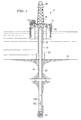
- FIGURE 1 depicts a drilling rig on which exemplary embodiments of the present invention may be deployed.
- FIGURE 2 is a perspective view of the steering tool shown on FIGURE 1 .
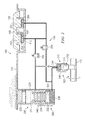
- FIGURE 3 depicts an exemplary hydraulic circuit in which exemplary embodiments of the present invention may be deployed.
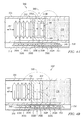
- FIGURE 4A depicts one exemplary embodiment of a position sensor, in accordance with the present invention, deployed on a hydraulic piston.
- FIGURE 4B depicts another exemplary embodiment of a position sensor, in accordance with the present invention, deployed on the hydraulic piston shown on figure 4A .
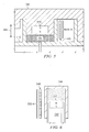
- FIGURE 5 depicts an exemplary embodiment of a position sensor deployed on a blade.
- FIGURE 6 depicts an exemplary embodiment of a position sensor deployed on a pump.
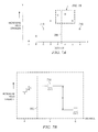
- FIGURE 7A depicts a graph of magnetic field strength versus distance for an exemplary data set measured by the sensor arrangement depicted on FIGURE 4A .
- FIGURE 7B depicts a portion of the graph shown on FIGURE 7A about the maximum.
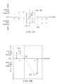
- FIGURE 8A depicts a graph of magnetic field strength versus distance for an exemplary data set measured by the sensor arrangement depicted on FIGURE 4B .
- FIGURE 8B depicts a portion of the graph shown on FIGURE 8A about the zero-crossing.
- FIGURES 1 to 6 it will be understood that features or aspects of the embodiments illustrated may be shown from various views. Where such features or aspects are common to particular views, they are labeled using the same reference numeral. Thus, a feature or aspect labeled with a particular reference numeral on one view in FIGURES 1 to 6 may be described herein with respect to that reference numeral shown on other views.
- FIGURE 1 illustrates a drilling rig 10 suitable for utilizing exemplary downhole tool and method embodiments of the present invention.
- a semisubmersible drilling platform 12 is positioned over an oil or gas formation (not shown) disposed below the sea floor 16.
- a subsea conduit 18 extends from deck 20 of platform 12 to a wellhead installation 22.
- the platform may include a derrick 26 and a hoisting apparatus 28 for raising and lowering the drill string 30, which, as shown, extends into borehole 40 and includes a drill bit 32 and a directional drilling tool 100 (such as a three-dimensional rotary steerable tool).
- steering tool 100 includes one or more, usually three, blades 150 disposed to extend outward from the tool 100 and apply a lateral force and/or displacement to the borehole wall 42.
- the extension of the blades deflects the drill string 30 from the central axis of the borehole 40, thereby changing the drilling direction.
- Drill string 30 may further include a downhole drilling motor, a mud pulse telemetry system, and one or more additional sensors, such as LWD and/or MWD tools for sensing downhole characteristics of the borehole and the surrounding formation.
- additional sensors such as LWD and/or MWD tools for sensing downhole characteristics of the borehole and the surrounding formation. The invention is not limited in these regards.
- rotary steerable tool 100 is substantially cylindrical and includes threaded ends 102 and 104 (threads not shown) for connecting with other bottom hole assembly (BHA) components (e.g., connecting with the drill bit at end 104).
- the rotary steerable tool 100 further includes a housing 110 deployed about a shaft (not shown in FIGURE 2 ).
- the shaft is typically configured to rotate relative to the housing 110.
- the housing 110 further includes at least one blade 150 deployed, for example, in a recess (not shown) therein.
- Directional drilling tool 100 further includes hydraulics 130 and electronics 140 modules (also referred to herein as control modules 130 and 140) deployed in the housing 110.
- the control modules 130 and 140 are configured for sensing and controlling the relative positions of the blades 150.
- one or more of blades 150 are extended and exert a force against the borehole wall.
- the rotary steerable tool 100 is moved away from the center of the borehole by this operation, thereby altering the drilling path.
- increasing the offset i.e., increasing the distance between the tool axis and the borehole axis via extending one or more of the blades
- the tool 100 may also be moved back towards the borehole axis if it is already eccentered. It will be understood that the drilling direction (whether straight or curved) is determined by the positions of the blades with respect to housing 110.
- a more precise determination (measurement) of the positions of the blades 150 relative to the housing 110 tends to yield a more precise and predictable drilling direction. More precise determination of the blade positions also provides for more precise borehole caliper measurements. Additionally, improving the reliability of the position sensor apparatus tends to improve the reliability of the tool (particularly the steering functionality of the tool).
- FIGURE 3 a schematic of one exemplary hydraulic module 130 ( FIGURE 2 ) used to control blade 150 is depicted.
- FIGURE 3 is a simplified schematic showing only a single blade. It will be understood that steering tools typically employ a plurality of blades, three being most common.
- Hydraulic module 130 includes a hydraulic fluid chamber 220 including first and second, low- and high-pressure reservoirs 226 and 236.
- low-pressure reservoir 226 is modulated to wellbore (hydrostatic) pressure via equalizer piston 222.
- Hydraulic fluid in chamber 236 is pressurized by pump 240, which is energized by rotating shaft 115.
- hydraulic fluid chamber 220 further includes a pressurizing spring 234 (e.g., a Belleville spring) deployed between an internal shoulder 221 of the chamber housing and a high-pressure piston 232.
- a pressurizing spring 234 e.g., a Belleville spring
- high-pressure piston 232 compresses spring 234, which maintains the pressure in the high-pressure reservoir 236 at some predetermined pressure above wellbore pressure.
- the volume of pressurized fluid in chamber 236 is related to the position of piston 232 in chamber 220.
- valves 254 and 256 Transmission of hydraulic pressure to blade 150 is controlled by solenoid-controlled valves 254 and 256. Opening valve 254 and closing valve 256 causes high-pressure hydraulic fluid to flow into chamber or reservoir 264. As chamber 264 is filled with pressurized fluid, piston 252 is urged radially outward, which in turn urges blade 150 outward from housing 110 (e.g., into contact with the borehole wall). When the blade 150 has been extended to a desired (predetermined) position, valve 254 may be closed, thereby "locking" the blade 150 in position (at the desired extension from the tool body). In order to retract the blade (radially inward towards the tool body), valve 256 is open (while valve 254 remains closed).
- Opening valve 256 allows pressurized hydraulic fluid in chamber 264 to return to the low-pressure reservoir 226.
- Blade 150 may be urged inward (towards the tool body), for example, via spring bias and/or contact with the borehole wall. In the exemplary embodiment shown, the blade 150 is not drawn inward under the influence of a hydraulic force, although the invention is not limited in this regard.
- Hydraulic module 130 further includes position sensors 300, 400, and 500 in accordance with the present invention.
- Position sensor 300 includes a magnet assembly 360 deployed in or on piston 232 and a substantially linear magnetic sensor array 340 deployed on chamber 220 in sensory range of magnetic flux emanating from the magnet assembly 360.
- Position sensor 300 is disposed to measure the position of high pressure piston 232 in chamber 220 and therefore is further disposed to measure the volume of high pressure hydraulic fluid in reservoir 236.
- Position sensor 400 includes magnet assembly 410 deployed in or on piston 252 (i.e., in or on blade 150) and a substantially linear magnetic sensor array 440 deployed adjacent chamber 264 in sensory range of magnetic flux emanating from magnet assembly 410.
- Position sensor 400 is disposed to measure the position of blade pistons 252 in chamber 264 and therefore is further disposed to measure the extension of the blade 150 relative to the housing 110 (or the tool axis).
- Position sensor 500 includes magnet assembly 510 deployed in or on piston 242 and a substantially linear sensor array 540 deployed adjacent pump housing 244.
- Position sensor 500 is disposed to measure the position of piston 242 in housing 244.
- Magnetic sensor arrays 340, 440, and 540 may include substantially any type of magnetic sensor, e.g., including magnetometers, reed switches, magnetoresistive sensors, and/or Hall-Effect sensors.
- each sensor may have either a ratiometric (analog) or digital output. While the exemplary embodiments described below with respect to FIGURES 4A through 5 advantageously utilize Hall-Effect sensors, the invention is not limited in this regard.
- FIGURE 4A depicts one exemplary embodiment of position sensor 300.
- a linear array 340 of Hall-Effect sensors 350A-H is deployed in a pressure resistant housing 310, which is located, for example, along an outer surface of hydraulic housing 305.
- FIGURE 4A shows an array of eight magnetic sensors, it will be appreciated by those of ordinary skill on the art that this invention may equivalently utilize substantially any suitable plurality of magnetic sensors (with three or more being preferred and five or more being most preferred).
- sensor array 340 further includes a microprocessor 355 electronically coupled with the sensors 350A-H.
- magnet assembly 360 is deployed on movable piston 232.
- magnet assembly 360 includes first and second magnets 370A and 370B (typically, although not necessarily, of equal size and strength) deployed in a magnetically permeable housing 380.
- magnets 370A and 370B are deployed such that opposing magnetic poles face one another (e.g., the north pole on magnet 370A is adjacent to the north pole on magnet 370B).
- magnetic flux lines 315 emanate outward from between the magnets 370A and 370B along center plane 390.
- magnet assembly 360 produces a substantially radially symmetric magnetic flux about the cylindrical axis of piston 232. While the invention is not limited in this regard, such a radially symmetric configuration advantageously provides for rotational freedom about the longitudinal axis of the piston 232. As such, the piston 232 and/or magnet assembly 360 may rotate in housing 305 during drilling (e.g., due to the extreme tool vibration commonly encountered downhole) without substantially effecting the accuracy of the linear position measurements. Moreover, a radially symmetric configuration also advantageously provides for easier tool assembly in that there is no need to key the piston 232 or magnet assembly 360 to a precise rotational position in housing 305.
- Magnetic sensor array 340 lies substantially parallel to the direction of movement of piston 232. Moreover, each magnetic sensor 350A-H in the sensor array 340 is deployed so that its axis of sensitivity is substantially perpendicular to the array 340 (i.e., perpendicular to the direction of movement of piston 232 and parallel with center plane 390). It will be appreciated by those of ordinary skill in the art that a magnetic sensor is typically sensitive only to the component of the magnetic flux that is aligned (parallel) with the sensor's axis of sensitivity.
- magnet assembly 340 shown on FIGURE 4A results in magnetic flux lines 315 that are substantially perpendicular to the sensor array 340 where the center plane 390 intercepts the array 340. Therefore, the magnetic sensor 350A-H located closest to center plane 390 tends to sense the highest magnetic flux (magnetic field strength).
- magnetic sensor 350E (as shown on FIGURE 4A ) tends to measure the highest magnetic flux because (i) it closest to magnet assembly 340 and (ii) it is closest to plane 390 (therefore the magnetic flux tends to be substantially parallel with the magnetic sensor's axis of sensitivity). It is thus possible to approximate the position of the magnet, and thus the piston, by determining which magnetic sensor 350A-H measures the greatest magnetic field.
- magnet assembly 360' includes a cylindrical magnet having a cylindrical axis substantially parallel with direction 307.
- Magnet assembly 360' also advantageously produces a substantially radially symmetric magnetic flux about the cylindrical axis of piston 232.
- sensors 350A-H are disposed so that each sensor's axis of sensitivity is substantially perpendicular to sensor array 340 (and therefore parallel with center plane 390).
- the magnetic sensor closest to center plane 390 tends to measure the lowest magnetic flux.
- magnetic sensor 350E tends to sense the lowest flux despite being closer to magnet assembly 360' since the flux is nearly perpendicular to the sensor's axis of sensitivity (e.g., as shown at 315'). It is thus possible to approximate the position of the magnet, and thus the piston, by determining which magnetic sensor measures the lowest magnetic flux.
- each sensor 350A-H in sensor array 340 may alternatively be aligned so that its axis of sensitivity is parallel with the array 340 (and therefore perpendicular to center plane 390).
- the position of the magnet assembly 360' would be determined based on the maximum (rather than the minimum) measured flux.
- sensors 350A-H may also alternatively be aligned so that their axes of sensitivity are parallel with the array 340 (and therefore perpendicular to center plane 390).
- the position of the magnet assembly 360 would be determined based on the minimum (rather than the maximum) measured flux.
- position sensor 400 is disposed to measure the position of blade 150 ( FIGURES 2 and 3 ).
- blade 150 is in its fully retracted position within housing 110.
- magnet assembly 410 is fixed to an inner surface of the blade 150 (inside piston 252 as shown on FIGURE 3 ).
- the blade extends outward from a longitudinal axis of the tool in the direction of arrow 405.
- Magnetic sensor array 440 is deployed within the blade housing in close enough proximity to magnet assembly 410 such that at least one of the sensors 450A-H on sensor array 440 is in sensory range of magnetic flux emanating from the assembly 410.
- magnet assembly 410 is substantially similar to magnet assembly 360', although an assembly similar to magnet assembly 360 may also be equivalently utilized.
- Sensors 450A-H may be deployed having substantially any suitable alignment (e.g., parallel or perpendicular to array 440).
- the typical range of motion of a blade in a rotary steerable tool e.g., tool 100
- the typical range of motion of a blade in a rotary steerable tool is approximately one inch (2.54 cm).
- sensors 450A-H are preferably closely spaced (e.g., spaced at an interval of approximately 1/8 inch (0.32 cm) or less along the length of the array 440).
- the invention is not limited in this regard.
- FIGURE 5 depicts an exemplary embodiment in which the magnet assembly 410 is deployed in the blade 150 (e.g., in piston 252) and the array 440 of sensors 450A-H is deployed on the housing 110, the invention is expressly not limited in this regard. It will be understood that sensor 400 may be equivalently configured such that magnet assembly 410 is deployed on housing 110 and sensor array 440 is deployed in the blade 150.
- Position sensor 500 is disposed to measure the axial position of piston 242 in housing 244. As shown on FIGURES 3 and 6 , rotation of shaft 115 causes piston 242 to reciprocate in housing 244 (e.g., due to a cam on the shaft). Magnetic sensor array 540 is deployed on an outer surface of housing 244 in close enough proximity to magnet assembly 510 such that at least one of the sensors 550A-I is in sensory range of magnetic flux emanating from the assembly 510.
- magnet assembly 510 is substantially similar to magnet assembly 360', although an assembly similar to magnet assembly 360 may also be equivalently utilized.
- Sensors 550A-I may be deployed having substantially any suitable alignment (e.g., parallel or perpendicular to array 540).
- sensor embodiment 500 is disposed to measure several tool parameters.
- the stroke volume of pump 240 (the volume of fluid pumped per single rotation of shaft 115 in housing 110) may be determined in substantially real time during drilling by measuring the axial positions at the top and bottom of the piston stroke.
- the axial position of piston 242 in housing 244 indicates the rotational position of the shaft 115 relative to the housing 110.
- the rotation rate of the shaft 115 with respect to the housing 110 may further be determined from the periodic motion of piston 242 in housing 244. While such rotational position and rotation rate measurements are typically made using other sensor arrangements, it will be appreciated that sensor embodiment 500 advantageously provides for a redundant measure of these parameters. As is known to those of ordinary skill in the downhole arts, redundant measurement capabilities can be highly advantageous in demanding downhole environments in which sensor failures are not uncommon.
- downhole tools must typically be designed to withstand shock levels in the range of 1000G on each axis and vibration levels of 50G root mean square. Moreover, downhole tools are also typically subject to pressures ranging up to about 25,000 psi (172 megapascals) and temperatures ranging up to about 200 degrees C.
- sensor array 340 is shown deployed in a pressure resistant housing 310. Such an arrangement is preferred for downhole applications utilizing solid state magnetic field sensors such as Hall-Effect sensors and magnetoresistive sensors. While not shown on FIGURES 5 and 6 , sensor arrays 440 and 540 are also preferably deployed in corresponding pressure resistant housings.
- housing 310 includes a sealed, magnetically permeable, steel tube that is configured to resist downhole pressures which can damage sensitive electronic components.
- the sensor arrays (340, 440, and 540) are also typically encapsulated in a potting material 358 to improve resistance to shocks and vibrations.
- Magnetic assemblies 360, 360', 410, and 510 are also typically constructed in view of demanding downhole conditions. For example, suitable magnets must posses a sufficiently high Curie Temperature to prevent demagnetization at downhole temperatures.
- Samarium cobalt (SaCo 5 ) magnets are typically preferred in view of their high Curie Temperatures (e.g., from about 700 to 800 degrees C).
- magnet assemblies 360, 360', 410, and 510 are also typically (although not necessarily) deployed inside corresponding pistons 232, 252, and 242 in order to provide additional shock and vibration resistance.
- each magnetic sensor may be advantageously electronically coupled to the input of a microprocessor.
- the microprocessor serves to process the data received by the sensor array.
- any suitable microprocessor, logic gate, or hardware device able to execute logic may be utilized.
- a hybrid device including multiple magnetic sensors (e.g., Hall-Effect sensors) and a microprocessor in a single package may also be utilized. The invention is not limited in these regards.
- a suitable microprocessor such as a PIC16F630/676 Microcontroller available from Microchip
- a suitable microprocessor 355 is deployed on a printed circuit board with sensors 350A-H.
- the microprocessor output (rather than the signals from the individual magnetic sensors) is typically electronically coupled with a main processor which is deployed further away from the sensor array (e.g., deployed in control module 140 as shown on FIGURE 2 ).
- This configuration advantageously reduces wiring requirements in the body of the downhole tool, which is particularly important in smaller diameter tool embodiments (e.g., tools having a diameter of less than about 12 inches).
- Digital output from the embedded microprocessor also tends to advantageously reduce electrical interference in wiring to the main processor.
- Embedded microprocessor output may also be combined with a voltage source line to further reduce the number of wires required, e.g., one wire for combined power and data output and one wire for ground. This may be accomplished, for example, by imparting a high frequency digital signal to the voltage source line or by modulating the current draw from the voltage source line. Such techniques are known to those of ordinary skill in the art.
- microprocessor 355 includes processor-readable or computer-readable program code embodying logic, including instructions for calculating a precise linear position of an element, such as a piston or a blade, from the received magnetic sensor measurements. While substantially any logic routines may be utilized, it will be appreciated that logic routines requiring minimal processing power are advantageous for downhole applications (particularly for LWD, MWD, and directional drilling embodiments of the invention in which both electrical and electronic processing power are often severely limited).
- FIGURES 7A and 7B a graphical representation of one exemplary mathematical technique for determining the linear position is illustrated.
- the exemplary method embodiment described with respect to FIGURES 7A and 7B determines the linear position via locating the position of a maximum magnetic field in the array 340.
- FIGURE 7A plots the magnetic field measurements made at each of sensors 350A-H as a function of distance along array 340.
- Data points 710 represent the absolute value of the magnetic field strength as measured by the magnetic sensors 350AH.
- the maximum magnetic field strength (and therefore the position of plane 390) is located between sensors 350E and 350F.
- the position of plane 390 (and therefore the position of piston 232) may be determined as follows.
- P represents the linear position of plane 390 in the array
- L represents the distance interval between adjacent sensors in the array
- A represents the difference in the absolute value of the magnetic field between the first and second of the three consecutive data points
- B represents the difference in the absolute value of the magnetic field between the second and third of the three consecutive data points ( A and B are shown on FIGURE 7B )
- Data points 810 represent the magnetic field strength as measured by sensors 350A-H on FIGURE 4B .
- the position of center plane 390 is indicated by zero-crossing 820, the location on the array at which magnetic flux is substantially null and at which the polarity of the magnetic field changes from positive to negative (or negative to positive). Note that in the exemplary embodiment shown, the position of the zero crossing (and therefore the position of plane 390) is located between sensors 350D and 350E.
- processor 355 first selects adjacent sensors (e.g., sensors 350D and 350E) between which the sign of the magnetic field changes (from positive to negative or negative to positive).
- the position of the zero crossing 820 may then be determined, for example, by fitting a straight line through the data points on either side of the zero crossing (e.g., between the measurements made by sensors 350D and 350E in embodiment shown on FIGURE 8B ).
- the shape and strength of the magnet(s) may be advantageously configured, for example, to produce a highly linear flux regime in the vicinity of the zero-crossing.
- P represents the linear position of plane 390
- L represents the distance interval between adjacent sensors in the array
- a and B represent the absolute values of the magnetic field measured on either side of the zero crossing ( A and B are shown on FIGURE 7B )
- x 4 (sensor 350D).
- position sensing methods described above with respect to FIGURES 7A through 8B advantageously require minimal computational resources (minimal processing power), which is critical in downhole applications in which 8-bit microprocessors are commonly used. These methods also provide accurate position determination along the full length of the sensor array. For example, an accurate position may be determined even when the magnetic field maximum or zero crossing are located near the ends of the array (near the first or last sensor in the array).
- the zero crossing method e.g., as shown on FIGURES 8A and 8B ) tends to be further advantageous in that a wider sensor input range is available (from the negative to positive saturation limits of the sensors).
- position sensors in accordance with this invention may be utilized to measure the extension of caliper probes used in wireline applications (one such caliper probe is disclosed in U.S. Patent 6,339,886 ). Additionally, position sensors in accordance with this invention may also be utilized to measure hydraulic volume in an inflatable packer assembly, such as are commonly utilized in MWD, LWD, and wireline applications (one such packer assembly is disclosed in U.S. Patent 5,517,854 ).
Landscapes
- Engineering & Computer Science (AREA)
- Geology (AREA)
- Life Sciences & Earth Sciences (AREA)
- Mining & Mineral Resources (AREA)
- Physics & Mathematics (AREA)
- Environmental & Geological Engineering (AREA)
- Fluid Mechanics (AREA)
- General Life Sciences & Earth Sciences (AREA)
- Geochemistry & Mineralogy (AREA)
- General Physics & Mathematics (AREA)
- Mechanical Engineering (AREA)
- Geophysics (AREA)
- Measurement Of Length, Angles, Or The Like Using Electric Or Magnetic Means (AREA)
Applications Claiming Priority (1)
| Application Number | Priority Date | Filing Date | Title |
|---|---|---|---|
| US11/714,966 US7377333B1 (en) | 2007-03-07 | 2007-03-07 | Linear position sensor for downhole tools and method of use |
Publications (2)
| Publication Number | Publication Date |
|---|---|
| EP1967689A2 true EP1967689A2 (fr) | 2008-09-10 |
| EP1967689A3 EP1967689A3 (fr) | 2011-11-23 |
Family
ID=39426779
Family Applications (1)
| Application Number | Title | Priority Date | Filing Date |
|---|---|---|---|
| EP08250785A Withdrawn EP1967689A3 (fr) | 2007-03-07 | 2008-03-07 | Capteur à positionnement linéaire pour outils d'extraction |
Country Status (2)
| Country | Link |
|---|---|
| US (1) | US7377333B1 (fr) |
| EP (1) | EP1967689A3 (fr) |
Cited By (5)
| Publication number | Priority date | Publication date | Assignee | Title |
|---|---|---|---|---|
| US20110232115A1 (en) * | 2010-03-23 | 2011-09-29 | Baker Hughes Incorporated | Position-sensing device and method |
| GB2467077B (en) * | 2007-11-16 | 2012-06-27 | Baker Hughes Inc | Position sensor for a downhole completion device |
| WO2014089490A1 (fr) * | 2012-12-07 | 2014-06-12 | Halliburton Energy Services Inc. | Forage de puits parallèles pour applications sagd et puits de secours |
| WO2017065731A1 (fr) * | 2015-10-12 | 2017-04-20 | Halliburton Energy Services, Inc. | Étalonnage de capteur de gradient de champ magnétique |
| US12291959B2 (en) | 2022-08-15 | 2025-05-06 | Halliburton Energy Services, Inc. | Position sensor assembly with circumferential magnetic coupling for wellbore operations |
Families Citing this family (30)
| Publication number | Priority date | Publication date | Assignee | Title |
|---|---|---|---|---|
| US7967081B2 (en) * | 2006-11-09 | 2011-06-28 | Smith International, Inc. | Closed-loop physical caliper measurements and directional drilling method |
| US8118114B2 (en) * | 2006-11-09 | 2012-02-21 | Smith International Inc. | Closed-loop control of rotary steerable blades |
| US20080236819A1 (en) * | 2007-03-28 | 2008-10-02 | Weatherford/Lamb, Inc. | Position sensor for determining operational condition of downhole tool |
| US7836975B2 (en) * | 2007-10-24 | 2010-11-23 | Schlumberger Technology Corporation | Morphable bit |
| GB2460096B (en) * | 2008-06-27 | 2010-04-07 | Wajid Rasheed | Expansion and calliper tool |
| GB2473377A (en) * | 2008-07-04 | 2011-03-09 | Peak Well Solutions As | Trigger device for activating an action |
| NO20083040A (no) * | 2008-07-04 | 2009-10-26 | Peak Well Solutions As | Triggerinnretning for å aktivere en hendelse |
| US8278928B2 (en) * | 2008-08-25 | 2012-10-02 | Baker Hughes Incorporated | Apparatus and method for detection of position of a component in an earth formation |
| EP2438342B1 (fr) * | 2009-06-03 | 2018-08-29 | Control Products Inc. | Accumulateur hydraulique avec capteur de position |
| US8156798B1 (en) * | 2010-07-09 | 2012-04-17 | Hongfeng Bi | High pressure high temperature fluid densitometer |
| SG187083A1 (en) | 2010-07-23 | 2013-03-28 | Halliburton Energy Serv Inc | Method and apparatus for measuring linear displacment |
| US9038747B2 (en) | 2011-06-20 | 2015-05-26 | David L. Abney, Inc. | Adjustable bent drilling tool having in situ drilling direction change capability |
| US8829893B2 (en) | 2011-09-09 | 2014-09-09 | Honeywell International Inc. | Linear position sensor |
| US9273550B2 (en) * | 2012-08-28 | 2016-03-01 | Intelliserv, Llc | System and method for determining fault location |
| EP2778622B1 (fr) * | 2013-03-15 | 2024-08-28 | Hirschmann Automotive GmbH | Capteur de position magnétique doté de deux barres magnétiques à polarités opposées |
| US9422806B2 (en) | 2013-10-04 | 2016-08-23 | Baker Hughes Incorporated | Downhole monitoring using magnetostrictive probe |
| US9598642B2 (en) | 2013-10-04 | 2017-03-21 | Baker Hughes Incorporated | Distributive temperature monitoring using magnetostrictive probe technology |
| US9822633B2 (en) * | 2013-10-22 | 2017-11-21 | Schlumberger Technology Corporation | Rotational downlinking to rotary steerable system |
| US9988887B2 (en) * | 2014-05-08 | 2018-06-05 | Baker Hughes, A Ge Company, Llc | Metal bellows equalizer capacity monitoring system |
| GB2531782A (en) * | 2014-10-30 | 2016-05-04 | Roxar Flow Measurement As | Position indicator for determining the relative position and/or movement of downhole tool componenets and method thereof |
| US10024315B2 (en) | 2014-12-19 | 2018-07-17 | Schlumberger Technology Corporation | Pump operation procedure with piston position sensor |
| FR3038932B1 (fr) * | 2015-07-15 | 2018-08-17 | Saltel Ind | Dispositif d'isolation pour puits avec un disque de rupture |
| US10907412B2 (en) | 2016-03-31 | 2021-02-02 | Schlumberger Technology Corporation | Equipment string communication and steering |
| US10502024B2 (en) | 2016-08-19 | 2019-12-10 | Schlumberger Technology Corporation | Systems and techniques for controlling and monitoring downhole operations in a well |
| CN111279160A (zh) * | 2017-10-31 | 2020-06-12 | Qed环境系统有限责任公司 | 带循环计数器的地下水井流体泵 |
| CN111448764B (zh) | 2017-12-13 | 2022-03-25 | 星光随钻测量公司 | 电磁遥测发射机装置和泥浆脉冲-电磁遥测组件 |
| CN109209339B (zh) * | 2018-10-10 | 2022-05-13 | 大连理工大学盘锦产业技术研究院 | 用于带压作业接箍探测装置探头侧向力的确定方法及装置 |
| CA3099061A1 (en) | 2019-11-15 | 2021-05-15 | Op-Hygiene Ip Gmbh | Fluid dispenser with wake up sensor |
| JP7136137B2 (ja) * | 2020-01-29 | 2022-09-13 | Tdk株式会社 | 磁気センサ、磁気検出装置及び磁気検出システム |
| US12460482B2 (en) * | 2023-06-23 | 2025-11-04 | Halliburton Energy Services, Inc. | Absolute linear position for downhole tool using rotary potentiometer |
Citations (5)
| Publication number | Priority date | Publication date | Assignee | Title |
|---|---|---|---|---|
| US5517854A (en) | 1992-06-09 | 1996-05-21 | Schlumberger Technology Corporation | Methods and apparatus for borehole measurement of formation stress |
| US5603386A (en) | 1992-03-05 | 1997-02-18 | Ledge 101 Limited | Downhole tool for controlling the drilling course of a borehole |
| US6339886B1 (en) | 1998-12-22 | 2002-01-22 | Baker Hughes, Inc. | Remotely measured caliper for wellbore fluid sample taking instrument |
| US20030184305A1 (en) | 2002-04-01 | 2003-10-02 | Nobuyoshi Niina | Displacement measuring system and method |
| US20060131013A1 (en) * | 2004-12-20 | 2006-06-22 | Pathfinder Energy Services, Inc. | Magnetization of target well casing strings tubulars for enhanced passive ranging |
Family Cites Families (62)
| Publication number | Priority date | Publication date | Assignee | Title |
|---|---|---|---|---|
| US2373880A (en) | 1942-01-24 | 1945-04-17 | Lawrence F Baash | Liner hanger |
| US2603163A (en) | 1949-08-11 | 1952-07-15 | Wilson Foundry & Machine Compa | Tubing anchor |
| US2874783A (en) | 1954-07-26 | 1959-02-24 | Marcus W Haines | Frictional holding device for use in wells |
| US2880805A (en) | 1956-01-03 | 1959-04-07 | Jersey Prod Res Co | Pressure operated packer |
| US2915011A (en) | 1956-03-29 | 1959-12-01 | Welex Inc | Stabilizer for well casing perforator |
| US3968473A (en) | 1974-03-04 | 1976-07-06 | Mobil Oil Corporation | Weight-on-drill-bit and torque-measuring apparatus |
| DE3046122C2 (de) | 1980-12-06 | 1984-05-17 | Bergwerksverband Gmbh, 4300 Essen | Einrichtungen zur Herstellung zielgerichteter Bohrungen mit einer Zielbohrstange |
| US4416339A (en) | 1982-01-21 | 1983-11-22 | Baker Royce E | Bit guidance device and method |
| US4463814A (en) | 1982-11-26 | 1984-08-07 | Advanced Drilling Corporation | Down-hole drilling apparatus |
| EP0190529B1 (fr) | 1985-01-07 | 1988-03-09 | S.M.F. International | Dispositif d'actionnement à distance à commande de débit, en particulier pour l'actionnement d'un stabilisateur d'un train de tiges de forage |
| GB2178088B (en) | 1985-07-25 | 1988-11-09 | Gearhart Tesel Ltd | Improvements in downhole tools |
| GB2179736B (en) | 1985-08-30 | 1989-10-18 | Prad Res & Dev Nv | Method of analyzing vibrations from a drilling bit in a borehole |
| US4715451A (en) | 1986-09-17 | 1987-12-29 | Atlantic Richfield Company | Measuring drillstem loading and behavior |
| EP0286500A1 (fr) | 1987-03-27 | 1988-10-12 | S.M.F. International | Dispositif de forage à trajectoire contrôlée et procédé de réglage de trajectoire correspondant |
| DE3890497D2 (en) | 1987-06-16 | 1989-06-15 | Preussag Ag | Device for guiding a drilling tool and/or pipe string |
| GB2228326B (en) | 1988-12-03 | 1993-02-24 | Anadrill Int Sa | Method for determining the instantaneous rotation speed of a drill string |
| US4957173A (en) | 1989-06-14 | 1990-09-18 | Underground Technologies, Inc. | Method and apparatus for subsoil drilling |
| DE4017761A1 (de) | 1990-06-01 | 1991-12-05 | Eastman Christensen Co | Bohrwerkzeug zum abteufen von bohrungen in unterirdische gesteinsformationen |
| US6417666B1 (en) * | 1991-03-01 | 2002-07-09 | Digital Control, Inc. | Boring tool tracking system and method using magnetic locating signal and wire-in-pipe data |
| US5226332A (en) | 1991-05-20 | 1993-07-13 | Baker Hughes Incorporated | Vibration monitoring system for drillstring |
| GB9111381D0 (en) | 1991-05-25 | 1991-07-17 | Petroline Wireline Services | Centraliser |
| US5313829A (en) | 1992-01-03 | 1994-05-24 | Atlantic Richfield Company | Method of determining drillstring bottom hole assembly vibrations |
| US5448911A (en) | 1993-02-18 | 1995-09-12 | Baker Hughes Incorporated | Method and apparatus for detecting impending sticking of a drillstring |
| US5864058A (en) | 1994-09-23 | 1999-01-26 | Baroid Technology, Inc. | Detecting and reducing bit whirl |
| US6206108B1 (en) * | 1995-01-12 | 2001-03-27 | Baker Hughes Incorporated | Drilling system with integrated bottom hole assembly |
| CA2141086A1 (fr) | 1995-01-25 | 1996-07-26 | Gerhard Herget | Extensometre de contrainte rocheuse |
| FR2732403B1 (fr) | 1995-03-31 | 1997-05-09 | Inst Francais Du Petrole | Methode et systeme de prediction de l'apparition d'un dysfonctionnement en cours de forage |
| US5797453A (en) | 1995-10-12 | 1998-08-25 | Specialty Machine & Supply, Inc. | Apparatus for kicking over tool and method |
| US6068394A (en) | 1995-10-12 | 2000-05-30 | Industrial Sensors & Instrument | Method and apparatus for providing dynamic data during drilling |
| US5957221A (en) | 1996-02-28 | 1999-09-28 | Baker Hughes Incorporated | Downhole core sampling and testing apparatus |
| US5941323A (en) | 1996-09-26 | 1999-08-24 | Bp Amoco Corporation | Steerable directional drilling tool |
| GB9620679D0 (en) | 1996-10-04 | 1996-11-20 | Halliburton Co | Method and apparatus for sensing and displaying torsional vibration |
| US6609579B2 (en) | 1997-01-30 | 2003-08-26 | Baker Hughes Incorporated | Drilling assembly with a steering device for coiled-tubing operations |
| US6173793B1 (en) * | 1998-12-18 | 2001-01-16 | Baker Hughes Incorporated | Measurement-while-drilling devices with pad mounted sensors |
| CA2318033A1 (fr) | 1998-01-16 | 1999-07-22 | Numar Corporation | Procede et appareil de mesure de fond pendant le forage par resonance magnetique nucleaire |
| US6092610A (en) | 1998-02-05 | 2000-07-25 | Schlumberger Technology Corporation | Actively controlled rotary steerable system and method for drilling wells |
| US6158529A (en) | 1998-12-11 | 2000-12-12 | Schlumberger Technology Corporation | Rotary steerable well drilling system utilizing sliding sleeve |
| GB9902023D0 (en) | 1999-01-30 | 1999-03-17 | Pacitti Paolo | Directionally-controlled eccentric |
| US6267185B1 (en) | 1999-08-03 | 2001-07-31 | Schlumberger Technology Corporation | Apparatus and method for communication with downhole equipment using drill string rotation and gyroscopic sensors |
| US6216802B1 (en) | 1999-10-18 | 2001-04-17 | Donald M. Sawyer | Gravity oriented directional drilling apparatus and method |
| US6427783B2 (en) | 2000-01-12 | 2002-08-06 | Baker Hughes Incorporated | Steerable modular drilling assembly |
| US6608565B1 (en) | 2000-01-27 | 2003-08-19 | Scientific Drilling International | Downward communication in a borehole through drill string rotary modulation |
| US6439325B1 (en) | 2000-07-19 | 2002-08-27 | Baker Hughes Incorporated | Drilling apparatus with motor-driven pump steering control |
| US6647637B2 (en) | 2000-11-01 | 2003-11-18 | Baker Hughes Incorporated | Use of magneto-resistive sensors for borehole logging |
| US6681633B2 (en) | 2000-11-07 | 2004-01-27 | Halliburton Energy Services, Inc. | Spectral power ratio method and system for detecting drill bit failure and signaling surface operator |
| GB0103702D0 (en) | 2001-02-15 | 2001-03-28 | Computalog Usa Inc | Apparatus and method for actuating arms |
| US6518756B1 (en) | 2001-06-14 | 2003-02-11 | Halliburton Energy Services, Inc. | Systems and methods for determining motion tool parameters in borehole logging |
| US6742604B2 (en) | 2002-03-29 | 2004-06-01 | Schlumberger Technology Corporation | Rotary control of rotary steerables using servo-accelerometers |
| US6913095B2 (en) | 2002-05-15 | 2005-07-05 | Baker Hughes Incorporated | Closed loop drilling assembly with electronics outside a non-rotating sleeve |
| US7114565B2 (en) | 2002-07-30 | 2006-10-03 | Baker Hughes Incorporated | Measurement-while-drilling assembly using real-time toolface oriented measurements |
| US6761232B2 (en) | 2002-11-11 | 2004-07-13 | Pathfinder Energy Services, Inc. | Sprung member and actuator for downhole tools |
| CN100449268C (zh) | 2003-02-14 | 2009-01-07 | Bei传感器及系统有限公司 | 使用线性霍尔效应传感器、具有增强线性磁体配置的位置传感器 |
| US7195033B2 (en) * | 2003-02-24 | 2007-03-27 | Weatherford/Lamb, Inc. | Method and system for determining and controlling position of valve |
| US7082821B2 (en) | 2003-04-15 | 2006-08-01 | Halliburton Energy Services, Inc. | Method and apparatus for detecting torsional vibration with a downhole pressure sensor |
| US7168487B2 (en) * | 2003-06-02 | 2007-01-30 | Schlumberger Technology Corporation | Methods, apparatus, and systems for obtaining formation information utilizing sensors attached to a casing in a wellbore |
| US6848189B2 (en) | 2003-06-18 | 2005-02-01 | Halliburton Energy Services, Inc. | Method and apparatus for measuring a distance |
| GB2406344B (en) | 2003-07-01 | 2007-01-03 | Pathfinder Energy Services Inc | Drill string rotation encoding |
| US7678253B2 (en) | 2003-08-11 | 2010-03-16 | Mehrooz Zamanzadeh | Atmospheric corrosion sensor |
| US7394244B2 (en) | 2003-10-22 | 2008-07-01 | Parker-Hannifan Corporation | Through-wall position sensor |
| US20050150694A1 (en) | 2004-01-14 | 2005-07-14 | Validus | Method and apparatus for preventing the friction induced rotation of non-rotating stabilizers |
| US7219748B2 (en) * | 2004-05-28 | 2007-05-22 | Halliburton Energy Services, Inc | Downhole signal source |
| US7204325B2 (en) | 2005-02-18 | 2007-04-17 | Pathfinder Energy Services, Inc. | Spring mechanism for downhole steering tool blades |
-
2007
- 2007-03-07 US US11/714,966 patent/US7377333B1/en not_active Expired - Fee Related
-
2008
- 2008-03-07 EP EP08250785A patent/EP1967689A3/fr not_active Withdrawn
Patent Citations (5)
| Publication number | Priority date | Publication date | Assignee | Title |
|---|---|---|---|---|
| US5603386A (en) | 1992-03-05 | 1997-02-18 | Ledge 101 Limited | Downhole tool for controlling the drilling course of a borehole |
| US5517854A (en) | 1992-06-09 | 1996-05-21 | Schlumberger Technology Corporation | Methods and apparatus for borehole measurement of formation stress |
| US6339886B1 (en) | 1998-12-22 | 2002-01-22 | Baker Hughes, Inc. | Remotely measured caliper for wellbore fluid sample taking instrument |
| US20030184305A1 (en) | 2002-04-01 | 2003-10-02 | Nobuyoshi Niina | Displacement measuring system and method |
| US20060131013A1 (en) * | 2004-12-20 | 2006-06-22 | Pathfinder Energy Services, Inc. | Magnetization of target well casing strings tubulars for enhanced passive ranging |
Cited By (15)
| Publication number | Priority date | Publication date | Assignee | Title |
|---|---|---|---|---|
| GB2467077B (en) * | 2007-11-16 | 2012-06-27 | Baker Hughes Inc | Position sensor for a downhole completion device |
| US8237443B2 (en) | 2007-11-16 | 2012-08-07 | Baker Hughes Incorporated | Position sensor for a downhole completion device |
| GB2491325B (en) * | 2010-03-23 | 2017-09-20 | Baker Hughes Inc | Position-sensing device and method |
| WO2011119726A3 (fr) * | 2010-03-23 | 2012-01-19 | Baker Hughes Incorporated | Dispositif et procédé de détection de position |
| GB2491325A (en) * | 2010-03-23 | 2012-11-28 | Baker Hughes Inc | Position-sensing device and method |
| US8453527B2 (en) * | 2010-03-23 | 2013-06-04 | Baker Hughes Incorporated | Position-sensing device and method |
| US20110232115A1 (en) * | 2010-03-23 | 2011-09-29 | Baker Hughes Incorporated | Position-sensing device and method |
| NO342551B1 (no) * | 2010-03-23 | 2018-06-11 | Baker Hughes Inc | Posisjonsføleanordning og fremgangsmåte |
| WO2014089490A1 (fr) * | 2012-12-07 | 2014-06-12 | Halliburton Energy Services Inc. | Forage de puits parallèles pour applications sagd et puits de secours |
| CN104884736A (zh) * | 2012-12-07 | 2015-09-02 | 哈利伯顿能源服务公司 | 钻探用于sagd应用的平行井 |
| US10132157B2 (en) | 2012-12-07 | 2018-11-20 | Halliburton Energy Services, Inc. | System for drilling parallel wells for SAGD applications |
| US10995608B2 (en) | 2012-12-07 | 2021-05-04 | Halliburton Energy Services, Inc. | System for drilling parallel wells for SAGD applications |
| WO2017065731A1 (fr) * | 2015-10-12 | 2017-04-20 | Halliburton Energy Services, Inc. | Étalonnage de capteur de gradient de champ magnétique |
| US10677955B2 (en) | 2015-10-12 | 2020-06-09 | Halliburton Energy Services, Inc. | Two part magnetic field gradient sensor calibration |
| US12291959B2 (en) | 2022-08-15 | 2025-05-06 | Halliburton Energy Services, Inc. | Position sensor assembly with circumferential magnetic coupling for wellbore operations |
Also Published As
| Publication number | Publication date |
|---|---|
| US7377333B1 (en) | 2008-05-27 |
| EP1967689A3 (fr) | 2011-11-23 |
Similar Documents
| Publication | Publication Date | Title |
|---|---|---|
| US7377333B1 (en) | Linear position sensor for downhole tools and method of use | |
| US8484858B2 (en) | Wall contact caliper instruments for use in a drill string | |
| US8497685B2 (en) | Angular position sensor for a downhole tool | |
| US7725263B2 (en) | Gravity azimuth measurement at a non-rotating housing | |
| US8467268B2 (en) | Pressure release encoding system for communicating downhole information through a wellbore to a surface location | |
| US8024868B2 (en) | Wall contact caliper instruments for use in a drill string | |
| US11142955B2 (en) | Steerable drill bit system | |
| US8836325B2 (en) | Valve position sensor | |
| US20130220602A1 (en) | Downhole downlinking system employing a differential pressure transducer | |
| US11815352B2 (en) | Apparatus and method for determining borehole size with a borehole imaging tool | |
| US8824241B2 (en) | Method for a pressure release encoding system for communicating downhole information through a wellbore to a surface location | |
| US20160208953A1 (en) | Mud pulser with poppet valve, having linear displacement determination means | |
| CA2591386A1 (fr) | Transmetteur de pression de fond | |
| CA2746081C (fr) | Commutateur de detection de position sans contact | |
| WO2012094242A2 (fr) | Procédé pour un système de codage de dégagement de pression servant à communiquer à un emplacement à la surface des informations de fond à travers un puits de forage | |
| CA2879026A1 (fr) | Pulseur de boue dote d'un distributeur a clapet et de mecanismes de determination de deplacement lineaire | |
| US9024777B2 (en) | Active compensation for mud telemetry modulator and turbine |
Legal Events
| Date | Code | Title | Description |
|---|---|---|---|
| PUAI | Public reference made under article 153(3) epc to a published international application that has entered the european phase |
Free format text: ORIGINAL CODE: 0009012 |
|
| AK | Designated contracting states |
Kind code of ref document: A2 Designated state(s): AT BE BG CH CY CZ DE DK EE ES FI FR GB GR HR HU IE IS IT LI LT LU LV MC MT NL NO PL PT RO SE SI SK TR |
|
| AX | Request for extension of the european patent |
Extension state: AL BA MK RS |
|
| RAP1 | Party data changed (applicant data changed or rights of an application transferred) |
Owner name: SMITH INTERNATIONAL, INC. |
|
| RIC1 | Information provided on ipc code assigned before grant |
Ipc: E21B 47/08 20060101ALN20110628BHEP Ipc: E21B 7/06 20060101AFI20110628BHEP |
|
| PUAL | Search report despatched |
Free format text: ORIGINAL CODE: 0009013 |
|
| AK | Designated contracting states |
Kind code of ref document: A3 Designated state(s): AT BE BG CH CY CZ DE DK EE ES FI FR GB GR HR HU IE IS IT LI LT LU LV MC MT NL NO PL PT RO SE SI SK TR |
|
| AX | Request for extension of the european patent |
Extension state: AL BA MK RS |
|
| RIC1 | Information provided on ipc code assigned before grant |
Ipc: E21B 7/06 20060101AFI20111017BHEP Ipc: E21B 47/08 20060101ALN20111017BHEP |
|
| 17P | Request for examination filed |
Effective date: 20120523 |
|
| AKX | Designation fees paid |
Designated state(s): AT BE BG CH CY CZ DE DK EE ES FI FR GB GR HR HU IE IS IT LI LT LU LV MC MT NL NO PL PT RO SE SI SK TR |
|
| RAP1 | Party data changed (applicant data changed or rights of an application transferred) |
Owner name: SERVICES PETROLIERS SCHLUMBERGER Owner name: SCHLUMBERGER HOLDINGS LIMITED Owner name: SCHLUMBERGER TECHNOLOGY B.V. Owner name: PRAD RESEARCH AND DEVELOPMENT LIMITED |
|
| STAA | Information on the status of an ep patent application or granted ep patent |
Free format text: STATUS: EXAMINATION IS IN PROGRESS |
|
| 17Q | First examination report despatched |
Effective date: 20180213 |
|
| STAA | Information on the status of an ep patent application or granted ep patent |
Free format text: STATUS: THE APPLICATION IS DEEMED TO BE WITHDRAWN |
|
| 18D | Application deemed to be withdrawn |
Effective date: 20190726 |