EP1967772A2 - Gangschaltungsindikator und Gangschaltungsindikatorverfahren für Getriebe - Google Patents
Gangschaltungsindikator und Gangschaltungsindikatorverfahren für Getriebe Download PDFInfo
- Publication number
- EP1967772A2 EP1967772A2 EP08250754A EP08250754A EP1967772A2 EP 1967772 A2 EP1967772 A2 EP 1967772A2 EP 08250754 A EP08250754 A EP 08250754A EP 08250754 A EP08250754 A EP 08250754A EP 1967772 A2 EP1967772 A2 EP 1967772A2
- Authority
- EP
- European Patent Office
- Prior art keywords
- gear ratio
- consumption amount
- fuel consumption
- gear
- fuel
- Prior art date
- Legal status (The legal status is an assumption and is not a legal conclusion. Google has not performed a legal analysis and makes no representation as to the accuracy of the status listed.)
- Granted
Links
- 230000005540 biological transmission Effects 0.000 title claims abstract description 34
- 238000000034 method Methods 0.000 title claims description 25
- 239000000446 fuel Substances 0.000 claims abstract description 362
- 238000010586 diagram Methods 0.000 claims abstract description 13
- 230000008929 regeneration Effects 0.000 claims description 23
- 238000011069 regeneration method Methods 0.000 claims description 23
- 239000003054 catalyst Substances 0.000 abstract description 63
- 239000007789 gas Substances 0.000 description 45
- QVGXLLKOCUKJST-UHFFFAOYSA-N atomic oxygen Chemical compound [O] QVGXLLKOCUKJST-UHFFFAOYSA-N 0.000 description 20
- 229910052760 oxygen Inorganic materials 0.000 description 20
- 239000001301 oxygen Substances 0.000 description 20
- 238000001514 detection method Methods 0.000 description 12
- 238000002347 injection Methods 0.000 description 10
- 239000007924 injection Substances 0.000 description 10
- 238000002485 combustion reaction Methods 0.000 description 9
- 239000002585 base Substances 0.000 description 8
- 230000008569 process Effects 0.000 description 7
- 238000011144 upstream manufacturing Methods 0.000 description 7
- 230000009467 reduction Effects 0.000 description 6
- 230000006870 function Effects 0.000 description 5
- 239000003638 chemical reducing agent Substances 0.000 description 4
- 239000000203 mixture Substances 0.000 description 3
- BASFCYQUMIYNBI-UHFFFAOYSA-N platinum Chemical compound [Pt] BASFCYQUMIYNBI-UHFFFAOYSA-N 0.000 description 3
- PNEYBMLMFCGWSK-UHFFFAOYSA-N aluminium oxide Inorganic materials [O-2].[O-2].[O-2].[Al+3].[Al+3] PNEYBMLMFCGWSK-UHFFFAOYSA-N 0.000 description 2
- 239000011575 calcium Substances 0.000 description 2
- 239000000919 ceramic Substances 0.000 description 2
- 229910052593 corundum Inorganic materials 0.000 description 2
- 238000005516 engineering process Methods 0.000 description 2
- 239000002828 fuel tank Substances 0.000 description 2
- 229910001845 yogo sapphire Inorganic materials 0.000 description 2
- OYPRJOBELJOOCE-UHFFFAOYSA-N Calcium Chemical compound [Ca] OYPRJOBELJOOCE-UHFFFAOYSA-N 0.000 description 1
- OKTJSMMVPCPJKN-UHFFFAOYSA-N Carbon Chemical compound [C] OKTJSMMVPCPJKN-UHFFFAOYSA-N 0.000 description 1
- WHXSMMKQMYFTQS-UHFFFAOYSA-N Lithium Chemical compound [Li] WHXSMMKQMYFTQS-UHFFFAOYSA-N 0.000 description 1
- ZLMJMSJWJFRBEC-UHFFFAOYSA-N Potassium Chemical compound [K] ZLMJMSJWJFRBEC-UHFFFAOYSA-N 0.000 description 1
- KEAYESYHFKHZAL-UHFFFAOYSA-N Sodium Chemical compound [Na] KEAYESYHFKHZAL-UHFFFAOYSA-N 0.000 description 1
- 238000010521 absorption reaction Methods 0.000 description 1
- 230000001133 acceleration Effects 0.000 description 1
- 239000003513 alkali Substances 0.000 description 1
- 229910052783 alkali metal Inorganic materials 0.000 description 1
- 150000001340 alkali metals Chemical class 0.000 description 1
- 229910052788 barium Inorganic materials 0.000 description 1
- DSAJWYNOEDNPEQ-UHFFFAOYSA-N barium atom Chemical compound [Ba] DSAJWYNOEDNPEQ-UHFFFAOYSA-N 0.000 description 1
- 230000002457 bidirectional effect Effects 0.000 description 1
- 229910052792 caesium Inorganic materials 0.000 description 1
- TVFDJXOCXUVLDH-UHFFFAOYSA-N caesium atom Chemical compound [Cs] TVFDJXOCXUVLDH-UHFFFAOYSA-N 0.000 description 1
- 229910052791 calcium Inorganic materials 0.000 description 1
- 229910052799 carbon Inorganic materials 0.000 description 1
- 238000010276 construction Methods 0.000 description 1
- -1 kalium (K) Chemical class 0.000 description 1
- 229910052751 metal Inorganic materials 0.000 description 1
- 239000002184 metal Substances 0.000 description 1
- 238000012986 modification Methods 0.000 description 1
- 230000004048 modification Effects 0.000 description 1
- 229910052697 platinum Inorganic materials 0.000 description 1
- 238000012805 post-processing Methods 0.000 description 1
- 238000012545 processing Methods 0.000 description 1
- 238000000746 purification Methods 0.000 description 1
- 229910052761 rare earth metal Inorganic materials 0.000 description 1
- 230000001105 regulatory effect Effects 0.000 description 1
- 239000000758 substrate Substances 0.000 description 1
- 229910052727 yttrium Inorganic materials 0.000 description 1
- VWQVUPCCIRVNHF-UHFFFAOYSA-N yttrium atom Chemical compound [Y] VWQVUPCCIRVNHF-UHFFFAOYSA-N 0.000 description 1
Images


Classifications
-
- F—MECHANICAL ENGINEERING; LIGHTING; HEATING; WEAPONS; BLASTING
- F16—ENGINEERING ELEMENTS AND UNITS; GENERAL MEASURES FOR PRODUCING AND MAINTAINING EFFECTIVE FUNCTIONING OF MACHINES OR INSTALLATIONS; THERMAL INSULATION IN GENERAL
- F16H—GEARING
- F16H63/00—Control outputs from the control unit to change-speed- or reversing-gearings for conveying rotary motion or to other devices than the final output mechanism
- F16H63/40—Control outputs from the control unit to change-speed- or reversing-gearings for conveying rotary motion or to other devices than the final output mechanism comprising signals other than signals for actuating the final output mechanisms
- F16H63/42—Ratio indicator devices
-
- F—MECHANICAL ENGINEERING; LIGHTING; HEATING; WEAPONS; BLASTING
- F16—ENGINEERING ELEMENTS AND UNITS; GENERAL MEASURES FOR PRODUCING AND MAINTAINING EFFECTIVE FUNCTIONING OF MACHINES OR INSTALLATIONS; THERMAL INSULATION IN GENERAL
- F16H—GEARING
- F16H61/00—Control functions within control units of change-speed- or reversing-gearings for conveying rotary motion ; Control of exclusively fluid gearing, friction gearing, gearings with endless flexible members or other particular types of gearing
- F16H61/02—Control functions within control units of change-speed- or reversing-gearings for conveying rotary motion ; Control of exclusively fluid gearing, friction gearing, gearings with endless flexible members or other particular types of gearing characterised by the signals used
- F16H61/0202—Control functions within control units of change-speed- or reversing-gearings for conveying rotary motion ; Control of exclusively fluid gearing, friction gearing, gearings with endless flexible members or other particular types of gearing characterised by the signals used the signals being electric
- F16H61/0204—Control functions within control units of change-speed- or reversing-gearings for conveying rotary motion ; Control of exclusively fluid gearing, friction gearing, gearings with endless flexible members or other particular types of gearing characterised by the signals used the signals being electric for gearshift control, e.g. control functions for performing shifting or generation of shift signal
- F16H61/0213—Control functions within control units of change-speed- or reversing-gearings for conveying rotary motion ; Control of exclusively fluid gearing, friction gearing, gearings with endless flexible members or other particular types of gearing characterised by the signals used the signals being electric for gearshift control, e.g. control functions for performing shifting or generation of shift signal characterised by the method for generating shift signals
-
- F—MECHANICAL ENGINEERING; LIGHTING; HEATING; WEAPONS; BLASTING
- F16—ENGINEERING ELEMENTS AND UNITS; GENERAL MEASURES FOR PRODUCING AND MAINTAINING EFFECTIVE FUNCTIONING OF MACHINES OR INSTALLATIONS; THERMAL INSULATION IN GENERAL
- F16H—GEARING
- F16H61/00—Control functions within control units of change-speed- or reversing-gearings for conveying rotary motion ; Control of exclusively fluid gearing, friction gearing, gearings with endless flexible members or other particular types of gearing
- F16H2061/0015—Transmission control for optimising fuel consumptions
-
- F—MECHANICAL ENGINEERING; LIGHTING; HEATING; WEAPONS; BLASTING
- F16—ENGINEERING ELEMENTS AND UNITS; GENERAL MEASURES FOR PRODUCING AND MAINTAINING EFFECTIVE FUNCTIONING OF MACHINES OR INSTALLATIONS; THERMAL INSULATION IN GENERAL
- F16H—GEARING
- F16H61/00—Control functions within control units of change-speed- or reversing-gearings for conveying rotary motion ; Control of exclusively fluid gearing, friction gearing, gearings with endless flexible members or other particular types of gearing
- F16H2061/0018—Transmission control for optimising exhaust emissions
-
- F—MECHANICAL ENGINEERING; LIGHTING; HEATING; WEAPONS; BLASTING
- F16—ENGINEERING ELEMENTS AND UNITS; GENERAL MEASURES FOR PRODUCING AND MAINTAINING EFFECTIVE FUNCTIONING OF MACHINES OR INSTALLATIONS; THERMAL INSULATION IN GENERAL
- F16H—GEARING
- F16H61/00—Control functions within control units of change-speed- or reversing-gearings for conveying rotary motion ; Control of exclusively fluid gearing, friction gearing, gearings with endless flexible members or other particular types of gearing
- F16H61/02—Control functions within control units of change-speed- or reversing-gearings for conveying rotary motion ; Control of exclusively fluid gearing, friction gearing, gearings with endless flexible members or other particular types of gearing characterised by the signals used
- F16H61/0202—Control functions within control units of change-speed- or reversing-gearings for conveying rotary motion ; Control of exclusively fluid gearing, friction gearing, gearings with endless flexible members or other particular types of gearing characterised by the signals used the signals being electric
- F16H61/0204—Control functions within control units of change-speed- or reversing-gearings for conveying rotary motion ; Control of exclusively fluid gearing, friction gearing, gearings with endless flexible members or other particular types of gearing characterised by the signals used the signals being electric for gearshift control, e.g. control functions for performing shifting or generation of shift signal
- F16H61/0213—Control functions within control units of change-speed- or reversing-gearings for conveying rotary motion ; Control of exclusively fluid gearing, friction gearing, gearings with endless flexible members or other particular types of gearing characterised by the signals used the signals being electric for gearshift control, e.g. control functions for performing shifting or generation of shift signal characterised by the method for generating shift signals
- F16H2061/022—Calculation or estimation of optimal gear ratio, e.g. best ratio for economy drive or performance according driver preference, or to optimise exhaust emissions
-
- F—MECHANICAL ENGINEERING; LIGHTING; HEATING; WEAPONS; BLASTING
- F16—ENGINEERING ELEMENTS AND UNITS; GENERAL MEASURES FOR PRODUCING AND MAINTAINING EFFECTIVE FUNCTIONING OF MACHINES OR INSTALLATIONS; THERMAL INSULATION IN GENERAL
- F16H—GEARING
- F16H63/00—Control outputs from the control unit to change-speed- or reversing-gearings for conveying rotary motion or to other devices than the final output mechanism
- F16H63/40—Control outputs from the control unit to change-speed- or reversing-gearings for conveying rotary motion or to other devices than the final output mechanism comprising signals other than signals for actuating the final output mechanisms
- F16H63/42—Ratio indicator devices
- F16H2063/426—Ratio indicator devices with means for advising the driver for proper shift action, e.g. prompting the driver with allowable selection range of ratios
Definitions
- the present invention relates to a gear shift indicator and a gear shift indication method for a transmission. More specifically, the present invention relates to a technology that indicates a gear shift in consideration of a fuel consumption amount when fuel addition is performed to regenerate a purifier that purifies- exhaust gas from an engine.
- a manual transmission that shifts gears according to an operation of a driver is well known.
- the driver can select any gear (gear ratio). Therefore, the gear selected by the driver is not always the best in regard to the vehicle fuel consumption (fuel economy). Accordingly, there is a vehicle provided with a GSI (Gear Shift Indicator) that indicates to the driver a gear shift to the gear determined in consideration of fuel consumption, or the like.
- GSI Gate Shift Indicator
- JP-A-2006-307877 describes a shift indication method for a transmission that makes a driver select the optimal gear position according to travel conditions of a vehicle provided with a diesel engine, a manual transmission, and a diesel particulate filter (DPF).
- DPF diesel particulate filter
- a first map for regular travel establishing a base gear position according to vehicle speed is changed over to a second map in which up-shift of the base gear position is shifted to a low vehicle speed side according to vehicle speed to calculate a target gear position according to vehicle speed.
- the target gear position is calculated by correcting the base gear position according to a fuel injection quantity, an engine rotation speed and vehicle acceleration.
- An up-shift is indicated if the target gear position is higher than an actual gear position and a downshift is indicated if the target gear position is lower than the actual gear position
- the base gear position is calculated according to the vehicle speed using the map in which the up-shift of the base gear position is shifted to the low vehicle speed side from that used during the regular traveling period. Therefore, while the regeneration of DPF is performed efficiently, the best gear position, in which the fuel economy is optimum, is indicated to the driver. At this time, if the up-shift is prompted earlier while the fuel economy (performance) is sacrificed to a certain extent, the temperature of the exhaust gas is increased to burn the particulate matters (PM) trapped by the DPF and the regeneration of DPF may be completed more rapidly (facilitated).
- PM particulate matters
- the purifier such as a DPF or a DPNR (Diesel Particulate-NOx Reduction system)
- fuel addition which adds fuel more than that required by vehicle traveling, may not always required.
- the temperature of the exhaust gas is high, no fuel addition is required for the regeneration process.
- the first map in which the base gear position is set based on vehicle speed during regular traveling, is changed over to the second map, in which the up-shift of the base gear position is shifted to the low vehicle speed side according to the vehicle speed. Accordingly, an up-shift may be prompted earlier, even in the case where no fuel addition is required for the regeneration process. In this case, fuel may be consumed more than necessary.
- the present invention provides a gear shift indicator and a gear shift indication method for a transmission that indicate a gear shift to the gear that reduces a fuel consumption amount.
- a first aspect of the present invention provides a gear shift indicator of a transmission in which a gear is shifted according to an operation of a driver.
- the gear shift indicator includes means for determining, for each of a first gear ratio and a second gear ratio of the transmission, whether fuel addition is performed to regenerate a purifier that purifies exhaust gas from an engine; means for calculating, for each of the first gear ratio and the second gear ratio, a first fuel consumption amount of the engine in a case where the fuel addition is not performed to regenerate the purifier; means for calculating, for each of the first gear ratio and the second gear ratio, a second fuel consumption amount of the engine in a case where the fuel addition is performed to regenerate the purifier; and indication means for comparing, when a current gear ratio of the transmission is the first gear ratio, one of the first fuel consumption amount and the second fuel consumption amount in the first gear ratio with one of the first fuel consumption amount and the second fuel consumption amount in the second gear ratio, and for indicating to the driver a shift from the first gear ratio to the second gear ratio
- a second aspect of the present invention provides a gear shift indication method for a transmission in which a gear is shifted according to an operation of a driver.
- the gear shift indication method includes step of determining, for each of a first gear ratio and a second gear ratio, whether fuel addition is performed to regenerate a purifier that purifies exhaust gas from an engine; step of calculating, for each of the first gear ratio and the second gear ratio, a first fuel consumption amount in the engine in a case where the fuel addition is not performed to regenerate the purifier; step of calculating, for each of the first gear ratio and the second gear ratio, a second fuel consumption amount of the engine in a case where the fuel addition is performed to regenerate the purifier; and step of indicating a shift to the second gear ratio to the driver by comparing, when a current gear of the transmission is the first gear ratio, one of the first fuel consumption amount and the second fuel consumption amount in the first gear ratio with one of the first fuel consumption amount and the second fuel consumption amount in the second gear ratio.
- the first fuel consumption amount of the engine in the case where fuel addition to regenerate the purifier is not performed and the second fuel consumption amount in the case where fuel addition is performed are calculated for each gear ratio.
- a shift to the second gear ratio is indicated to the driver by comparing one of the first fuel consumption amount and the second fuel consumption amount in the first gear ratio with one of the first fuel consumption amount and the second fuel consumption amount in the second gear ratio.
- the shift to the second gear ratio is indicated.
- a shift is indicated to a driver in consideration of the fuel consumption amount in the case where the purifier is regenerated without performing fuel addition. Accordingly, a shift to the gear in which the fuel consumption amount is smaller is indicated.
- a gear shift indicator or a gear shift indication method is provided that indicates a shift to the gear in which the fuel consumption amount is reduced.
- the indication means or the step of indicating the shift to the second gear ratio may compare the second fuel consumption amount in the first gear ratio with the second fuel consumption amount in the second gear ratio, and may indicate the shift to the second gear ratio when the second fuel consumption amount in the second gear ratio is smaller than the second fuel consumption amount in the first gear ratio.
- the second fuel consumption amount in the first gear ratio is compared with the second fuel consumption amount in the second gear ratio.
- the shift to the second gear ratio is indicated. Therefore, a shift to a gear in which the fuel consumption amount is smaller can be indicated.
- the indication means or the step of indicating the shift to the second gear ratio may compare the first fuel consumption amount in the first gear ratio with the first fuel consumption amount in the second gear ratio, and may indicate the shift to the second gear ratio when the first fuel consumption amount in the second gear ratio is smaller than the first fuel consumption amount in the first gear ratio.
- the first fuel consumption amount in the first gear ratio is compared with the first fuel consumption amount in the second gear ratio.
- the shift to the second gear ratio is indicated. Therefore, a shift to a gear in which the fuel consumption amount is smaller can be indicated.
- the indication means or the step of indicating the shift to the second gear ratio may compare the first fuel consumption amount in the first gear ratio with the second fuel consumption amount in the second gear ratio, and may indicate the shift to the second gear ratio when the second fuel consumption amount in the second gear ratio is smaller than the first fuel consumption amount in the first gear ratio.
- the fuel addition is not performed to regenerate the purifier in the first gear ratio and the fuel addition is performed to regenerate the purifier in the second gear ratio, the first fuel consumption amount in the first gear ratio is compared with the second fuel consumption amount of the second gear ratio.
- the second fuel consumption amount in the second gear ratio is smaller than the first fuel consumption amount in the first fear ratio, the shift to the second gear ratio is indicated. Therefore, a shift to a gear in which the fuel consumption amount is smaller can be indicated.
- the indication means or the step of indicating the shift to the second gear ratio may compare the second fuel consumption amount in the first gear ratio with the first fuel consumption amount in the second gear ratio, and may indicate the shift to the second gear ratio when the first fuel consumption amount in the second gear ratio is smaller than the second fuel consumption amount in the first gear ratio.
- the fuel addition is performed to regenerate the purifier in the first gear ratio and the fuel addition is not performed to regenerate the purifier in the second gear ratio, the second fuel consumption amount in the first gear ratio is compared with the first fuel consumption amount in the second gear ratio.
- the shift to the second gear ratio is indicated. Therefore, a shift to a gear in which the fuel consumption amount is smaller can be indicated.
- the power train includes an engine 10, a clutch 20 and a transmission 30.
- the gear shift indicator according to this embodiment is realized by, for example, performing program stored in a ROM (Read Only Memory) 1004 of an ECU (Electronic Control Unit) 1000, which will be described later.
- the program performed by the ECU 1000 may be stored in a storage medium, such as a CD (Compact Disc) or a DVD (Digital Versatile Disc), and may be distributed to the market.
- Torque of the engine 10 is transmitted to the transmission 30 via the clutch 20.
- the torque transmitted to the transmission 30 is further transmitted to driven wheels (not shown) via a drive shaft (not shown).
- the engine 10 will be described in detail later.
- the clutch 20 is a dry single plate friction clutch.
- the clutch 20 is released when a driver depresses a clutch pedal 40.
- the transmission 30 is a manual transmission that shifts gears when the driver operates a shift lever 50. Gearshift of the transmission 30 may be performed by an actuator based on a shift by the driver.
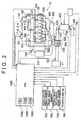
- the engine 10 is further described with reference to FIG 2 .
- the engine 10 continuously and simultaneously reduces PM and NOx by combining a high-pressure common rail fuel injector, a large capacity electronically controlled EGR (exhaust gas recirculation) cooler, and a DPNR catalyst.
- EGR exhaust gas recirculation
- Each catalyst includes a NSR (NOx Storage Reduction) catalyst that absorbs NOx, and a DPNR catalyst that removes PM, which is a particulate of carbon, or the like, and absorbs NOx.
- the NSR catalyst and the DPNR catalyst are disposed on an upstream side and on a downstream side, respectively. Note that this invention is not limited to the case in which two catalysts are provided. Further, the NSR catalyst is not limited to that constitutes a catalyst with the DPNR catalyst.
- the engine 10 is an inline four-cylinder diesel engine that includes a fuel supply system 100, a combustion changer 200, an intake system 300, an exhaust system 400 and the like, as principal portions.
- the fuel supply system 100 includes a supply pump 110, a common rail 120, a fuel injection valve 130, a cutoff valve 140, a control valve 160, a fuel addition nozzle 170, an engine fuel passage 800, an additional fuel passage 810, and the like.
- the supply pump 110 pumps up fuel from a fuel tank, raises the pressure of the pumped fuel, and supplies the high-pressure fuel to the common rail 120 via the engine fuel passage 800.
- the common rail 120 has a function as an accumulator chamber that maintains (or accumulates) the high pressure fuel supplied from the supply pump 110 at (or to) a predetermined pressure.
- the accumulated fuel is distributed to each fuel injection valve 130.
- an electromagnetic solenoid is provided in the fuel injection valve 130.
- the fuel injection valve 130 opens appropriately to inject and supplies fuel to the combustion chamber.
- the supply pump 110 supplies a portion of the fuel pumped up from the fuel tank to the fuel addition nozzle (reducing agent injection nozzle) 170 via the additional fuel passage 810.
- the cutoff valve 140 and the control valve 160 are provided in series in the additional fuel passage 810 from the supply pump 110 to the fuel addition nozzle 170.
- the cutoff valve 140 cuts off the additional fuel passage 810 in the event of emergency, and stops supplying fuel.
- the control valve 160 controls the pressure of the fuel supplied to the fuel addition nozzle 170 (fuel pressure).
- the fuel addition nozzle 170 opens when the fuel pressure is higher than a predetermined pressure (e.g., 0.2Mpa).
- the fuel addition nozzle is a mechanical on-off valve that injects and supplies fuel into the exhaust system 400 (exhaust port 410).
- the control valve 160 controls the fuel pressure upstream of the fuel addition nozzle 170, and a desired amount of fuel is injected and supplied (or added) from the fuel addition nozzle 170 at an appropriate timing.
- the intake system 300 forms an intake passage, which is a passage of intake air supplied to each combustion chamber 200.
- the exhaust system 400 is formed by connecting an exhaust port 410, an exhaust manifold 420, a catalyst upstream side passage 430 and a catalyst downstream side passage 440 in series from upstream side to downstream side.
- the exhaust system 400 forms an exhaust passage, which is a passage of exhaust gas discharged from each combustion chamber 200.
- the engine 10 is provided with a known booster device (turbocharger) 500.
- the turbocharger 500 is provided with a turbine wheel 520 and a turbine wheel 530 that are connected via a shaft 510.
- the turbine wheel (intake side turbine wheel) 530 is exposed to intake air in the intake system 300, and the turbine wheel (exhaust side turbine wheel) 520 is exposed to exhaust gas in the exhaust system 400.
- the turbocharger 500 as constructed above causes the intake side turbine wheel 520 to rotate by using the flow of exhaust gas (exhaust gas pressure) received by the exhaust side turbine wheel 520.
- the turbocharger 500 increases the intake pressure.
- an intercooler 310 disposed downstream of the turbocharger 500 forcibly cools the intake air that has been heated by the pressure increase.
- the throttle valve 320 disposed further downstream of the intercooler 310 is an electronically controlled open/close valve whose opening degree is adjustable steplessly or continuously.
- the flow passage area of intake air is reduced under a predetermined condition, to regulate (or reduce) the supply amount of intake air.
- the engine 10 has an exhaust gas recirculation passage (EGR passage) 600, which is a bypass passage connecting between the upstream (intake system 300) and the downstream (exhaust system 400) of the combustion chamber 200.
- the EGR passage 600 has a function to return a portion of exhaust gas to the intake system 300, as appropriate.
- an EGR valve 610 and an EGR cooler 620 are provided in the EGR passage 600.
- the EGR valve 610 is electronically controlled to open and close steplessly and is capable of regulating a flow volume of exhaust gas flowing through the EGR passage 600.
- the EGR cooler 620 cools recirculated exhaust gas that passes though the EGR passage 600.
- a catalyst 450 formed of the NSR catalyst and the DPNR catalyst is provided downstream of the exhaust side turbine wheel 520 (between the catalyst upstream side passage 430 and the catalyst downstream side passage 440).
- the NSR catalyst is a NOx storage reduction catalyst, in which, for example, almina (Al 2 O 3 ) as a substrate carries or supports alkali metals, such as kalium (K), natrium (Na), litium (Li) or cesium (Ce), alkali earths, such as barium (Ba) or calcium (Ca), or rare earth elements, such as lantern (La) or yttrium (Y).
- almina (Al 2 O 3 ) also carries a rare metal, such as platinum (Pt).
- the NSR catalyst absorbs NOx in a condition in which exhaust gas includes a great amount of oxygen.
- the NSR catalyst reduces NOx to NO 2 or NO to release. NOx released as NO 2 or NO reacts quickly with HC or CO in exhaust gas and is further reduced to N 2 .
- HC or CO itself is oxidized to be H 2 O or CO 2 .
- oxygen concentration or HC component in exhaust gas introduced into the NSR catalyst is controlled appropriately, HC, CO and NOx in exhaust gas is purified.
- the DPNR catalyst is formed by combining a porous ceramic structure with NOx storage reduction catalyst. While exhaust gas from the engine 10 passes through gaps in the ceramics, the exhaust gas is oxidized or reduced by the catalyst, and is chemically-altered to harmless gas to discharge.
- PM is temporarily trapped by the porous structured catalyst.
- PM is oxidized and purified by active oxygen generated when NOx is stored and oxygen in the exhaust gas.
- NOx is once stored in the catalyst during the lean-burn operation, and then, is reduced and purified during an instantaneous or momentary rich-burn (during a combustion with rich air fuel ratio and small amount of oxygen) operation.
- PM is oxidized and purified by active oxygen generated when the stored NOx is reduced during the rich burn operation.
- Various sensors are attached to respective portions of the engine 10, and respectively output circumstantial conditions or signals with respect to the operating conditions of the engine 10.
- a rail pressure sensor 700 outputs a detection signal according to a pressure of fuel stored or accumulated in the common rail 120.
- a fuel pressure sensor 710 outputs a detection signal according to a pressure (fuel pressure) Pg of fuel introduced into the control valve 160 in the fuel flowing in the additional fuel passage 810.
- An airflow meter 720 outputs a detection signal according to a flow volume (intake air volume) Ga of intake air downstream of the throttle valve 320 in the intake system 300.
- An air fuel ratio (A/F) sensor 730 outputs a detection signal that continuously changes according to the oxygen concentration in exhaust gas downstream of the catalyst casing in the exhaust system 400.
- An exhaust temperature sensor 740 outputs a detection signal according to the temperature (exhaust temperature) Tex of exhaust gas downstream of the catalyst casing in the exhaust system 400.
- An accelerator angle sensor 750 is attached to an accelerator pedal of the engine 10, and outputs a detection signal in accordance with an amount of depression of the accelerator pedal (an accelerator angle) Acc.
- a crank angle sensor 760 outputs a detection signal (pulse) every time an output shaft (crankshaft) rotates by a predetermined angle.
- An engine rotation speed NE is detected from the detection signal of the crank angle sensor 760.
- An output shaft rotational speed sensor 770 outputs a detection signal (pulse) every time the output shaft of the transmission 30 rotates by a constant angle. Vehicle speeds are detected from the detection signals of the output shaft rotational speed sensor 770.
- a position switch 780 outputs a detection signal corresponding to a position of the shift lever 50, that is, a currently selected gear in the transmission 30.
- Each of the sensors 700-770 and the switch 780 is electrically connected to the ECU 1000.
- the ECU 1000 includes a CPU (Central Processing Unit) 1002, a ROM 1004, a RAM (Random Access Memory) 1006, a timer, a counter, and the like, and is formed by connecting, via a bidirectional bus, the above components, an external input circuit including an A/D (Analog/Digital) converter, and an external output circuit.
- a CPU Central Processing Unit
- ROM Read Only Memory
- RAM Random Access Memory
- the ECU 1000 formed as described above, receives detection signals of the above-described various sensors through the external input circuit, and performs various control with respect to operating states of the engine 10, such as reducing agent (fuel) addition control to determine an addition timing and an amount supplied with respect to the addition of the reducing agent (fuel functioning as reducing agent), in addition to basic control with respect to fuel injection or the like of the engine 10 based on the above-described signals.
- the oxygen concentration in air-fuel mixture to be burned in the combustion chamber is in a state of high concentration in most of operating regions.
- the oxygen concentration in the air-fuel mixture to be burned is directly reflected in the oxygen concentration in exhaust gas, while burned oxygen is subtracted therefrom.
- the oxygen concentration (air-fuel ratio) in the air-fuel mixture is high, the oxygen concentration (air-fuel ratio) in the exhaust gas is basically high as well.
- the NOx storage reduction catalyst absorbs NOx when the oxygen concentration in exhaust gas is high, and reduces NOx to NO 2 or NO and releases them when the oxygen concentration in exhaust gas is low.
- NOx is absorbed. Note that, however, if the catalyst has a limit in the amount of NOx to be absorbed, and is in the state where the catalyst has absorbed the limit amount of NOx, NOx in exhaust gas is not absorbed by the catalyst and passes through the catalyst casing.
- exhaust addition fuel is added in the exhaust system 400 upstream of the catalyst 450 through the fuel addition nozzle 170 at an appropriate time (hereinafter, "exhaust addition"), thereby temporarily reducing the oxygen concentration in the exhaust gas and increasing the amount of reducing components (such as HC). Then, the catalyst 450 reduces the NOx absorbed up to then to NO 2 or NO and releases them. Thus, the catalyst 450 recovers (regenerates) the NOx absorption capacity thereof. The released NO 2 or NO reacts with HC or CO to be quickly reduced to N 2 , as described above.
- the efficiency of the reduction and purification is determined based on the amount of reducing components (fuel concentration) and the oxygen concentration (air-fuel ratio) in the exhaust gas flowing into the catalyst casing.
- the PM accumulated in the DPNR is burned by the exhaust gas whose temperature is increased for a regeneration process, and the burned PM further increases the temperature of the exhaust gas, thereby burning more PM.
- the PM trapping capability of DPNR is regenerated.
- additional fuel of the amount determined based on the operating state of the engine and the value measured by the temperature sensors disposed before and after the DPNR is added. More specifically, the additional fuel amount for PM regeneration is determined in consideration of combustion state or fuel injection state in the engine.
- the ECU 1000 detects the state quantities from the various sensors, and performs an operation for estimating the amount of trapped PM.
- the fuel injection amount from the fuel addition nozzle 170 is as less as possible to improve the fuel economy.
- the PM regeneration is performed efficiently by effectively using the heat of PM burning and is completed in a time period as short as possible.
- the fuel addition (fuel addition control) to the exhaust system is performed such that, in the engine 10, an appropriate amount of reducing components and air-fuel ratio in the exhaust gas, and an appropriate temperature of the exhaust gas are stably obtained.
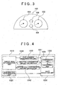
- the combination meter 900 of the vehicle on which the gear shift indicator according to the embodiment of the present invention will be described with reference to FIG 3 .
- the combination meter 900 includes an up-shift indicator lamp 906 and a downshift indicator lamp 908 in addition to a speedometer 902 and a tachometer 904.
- the up-shift indicator lamp 906 turns on or flashes, for example, to indicate an up-shift operation to the driver.
- the downshift indicator lamp 908 turns on or flashes, for example, to indicate a downshift operation to the driver.
- an up-shift operation or a downshift operation may be indicated with sounds.
- ECU 1000 The functions of ECU 1000 will be described with reference to FIG. 4 .
- the functions of ECU 1000 described below may be realized by hardware or software.
- the ECU 1000 includes a target gear determination unit 1010, a regeneration determination unit 1020, a fuel addition determination unit 1030, a first fuel consumption amount calculator 1041, a second fuel consumption amount calculator 1042 and a shift indication unit 1050.
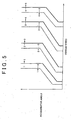
- the target gear determination unit 1010 determines a target gear, which is a gear to be indicated to the driver, based on, for example, a shifting diagram shown in FIG. 5 .
- the shifting diagram in this embodiment is defined by accelerator angles and vehicle speeds as parameters.
- solid lines are up-shift lines, and broken lines are downshift lines.
- the parameters of the shifting diagram are not limited thereto.
- the regeneration determination unit 1020 determines whether regeneration of the catalyst 450 is necessary. Whether the regeneration is necessary is determined by, for example, determining whether the value obtained by summing loads (intake air amounts) of the engine 10 after the previous regeneration is performed exceeds a threshold value. Incidentally, the method to determine whether regeneration is necessary is not limited thereto. Other well-known common techniques may be utilized, instead.
- the fuel addition determination unit 1030 determines, in each gear of the transmission 30, whether the fuel addition from the fuel addition nozzle 170 is necessary (or is performed) to regenerate the catalyst 450.
- the temperature of the exhaust gas detected by the exhaust temperature sensor 740 is smaller than a threshold value, it is determined that fuel addition is necessary in the current gear.
- the temperature of the exhaust gas detected by the exhaust temperature sensor 740 is larger than the threshold value, it is determined that fuel addition is not necessary in the current gear.
- the temperature of the exhaust gas in the target gear which is estimated from a map having a temperature of exhaust gas detected by the exhaust temperature sensor 740, a current gear and a target gear as parameters, is smaller than the threshold value, it is determined that fuel addition is necessary in the target gear. If the estimated temperature of the exhaust gas is larger than the threshold value, it is determined that fuel addition is not necessary in the target gear. Note that the method to determine whether fuel addition is necessary is not limited thereto.
- the first fuel consumption amount calculator 1041 calculates a first fuel consumption amount for each gear of the transmission 30.
- the first fuel consumption amount is a fuel consumption amount (fuel consumption rate) of the engine 10 when the fuel addition to regenerate the catalyst 450 is not necessary (is not performed).
- the second fuel consumption amount calculator 1042 calculates a second fuel consumption amount for each gear of the transmission 30.
- the second fuel consumption amount is a fuel consumption amount of the engine 10 when the fuel addition to regenerate the catalyst 450 is necessary (is performed).
- the fuel consumption amount is calculated according to, for example, a map using output torque of engine 10 and an engine rotational speed NE as parameters.
- the map is defined for each gear.
- the output torque of engine 10 is calculated from, for example, an accelerator angle Acc, an intake air amount Ga, an engine rotational speed NE, or the like. Note that the methods for calculating the fuel consumption amount and the output torque are not limited thereto, but a well-known common technology may be utilized.
- the first fuel consumption amount and the second fuel consumption amount in the target gear may be calculated using, for example, an engine rotational speed NE estimated by multiplying the output shaft rotational speed of the transmission 30 by the gear ratio of the target gear, instead of the engine rotational speed NE detected by use of the crank angle sensor 760.
- the shift indication unit 1050 includes a comparison unit 1054 and an indication unit 1054.
- the comparison unit 1052 compares the fuel consumption amount in the current gear, which is detected using the position switch 780, and the fuel consumption amount in the target gear.
- the second fuel consumption amount in the current gear is compared with the second fuel consumption amount in the target gear.
- the first fuel consumption amount in the current gear is compared with the first fuel consumption amount in the target gear.
- the first fuel consumption amount in the current gear is compared with the second fuel consumption amount in the target gear.
- the second fuel consumption amount in the current gear is compared with the first fuel consumption amount in the target gear.
- the first fuel consumption amount in the current gear is compared with the first fuel consumption amount in the target gear, in the same manner as the case in which the fuel addition is necessary neither in the current gear nor in the target gear.
- the indication unit 1054 indicates to the driver a shift to the target gear using the up-shift indicator lamp 906 or the downshift indicator lamp 908, when the fuel consumption amount in the target gear is smaller than the fuel consumption amount in the current gear of the transmission 30.
- the target gear is a gear with a speed higher than (or a gear with a gear ratio lower than) that of the current gear
- an up-shift operation to the target gear is indicated using the up-shift indicator lamp 906.
- the target gear is a gear with a speed lower than (or a gear with a gear ratio higher than) that of the current gear
- a downshift operation to the target gear is indicated by the downshift indicator lamp 908.
- a control structure of the program performed by the ECU 1000 which is a shift indication device according to the embodiment with reference to FIG 6 .
- step 10 the ECU 1000 detects the position of the shift lever 50, i.e., the current selected gear in the transmission 30, based on the signal transmitted from the position switch 780.
- step 20 the ECU 1000 determines the target gear in accordance with a shifting diagram.
- the ECU 1000 calculates a first fuel consumption amount, which is a fuel consumption amount of the engine 10 when fuel addition to regenerate the catalyst 450 is not necessary, for each of the current gear and the target gear.
- the ECU 1000 calculates a second fuel consumption amount, which is a fuel consumption amount of the engine 10 when fuel addition to regenerate the catalyst 450 is necessary, for each of the current gear and the target gear.
- the ECU 1000 determines whether the regeneration of the catalyst 450 is necessary. If it is determined that the regeneration of the catalyst 450 is necessary (YES in S50), the process proceeds to S60. If not (NO in S50), the process proceeds to S70.
- the ECU 1000 determines whether fuel addition from the fuel addition nozzle 170 to regenerate the catalyst 450 is necessary in each of the current gear and the target gear.
- the ECU 1000 determines whether the fuel consumption amount in the target gear is smaller than the fuel consumption amount in the current gear.
- the regeneration of the catalyst 450 is not necessary, it is determined whether the first fuel consumption amount in the target gear is smaller than the first fuel consumption amount in the current gear, as in the case in which fuel addition is necessary neither in the current gear nor in the target gear.
- the position of the shift lever 50 i.e., the gear currently selected in the transmission 30 is detected based on the signal transmitted from the position switch 780 (S10).
- the target gear is also determined in accordance with the shifting diagram (S20).
- the first fuel consumption amount of the engine 10 in the case where fuel addition to regenerate the catalyst 450 is not necessary is calculated for each of the current gear and the target gear (S30).
- the second fuel consumption amount of the engine 10 in the case where fuel addition to regenerate the catalyst 450 is necessary' is calculated for each of the current gear and the target gear (S40).
- the first fuel consumption amount and the second fuel consumption amount are calculated for each of the current gear and the target gear.
- the first fuel consumption amount is a fuel consumption amount of the engine when the fuel addition to regenerate the catalyst is not necessary.
- the second fuel consumption is a fuel consumption amount of the engine when the fuel addition is necessary.
- One of the first fuel consumption amount and the second fuel consumption amount in the current gear is compared with one of the first fuel consumption amount and the second fuel consumption amount in the target gear, and a shift to the target gear is indicated.
- a shift is indicated to the driver in consideration of the fuel consumption amount when the catalyst is regenerated without fuel addition. Accordingly, a shift to the gear in which the fuel consumption amount is smaller is indicated to the driver.
Landscapes
- Engineering & Computer Science (AREA)
- General Engineering & Computer Science (AREA)
- Mechanical Engineering (AREA)
- Control Of Transmission Device (AREA)
- Arrangement And Mounting Of Devices That Control Transmission Of Motive Force (AREA)
Applications Claiming Priority (1)
| Application Number | Priority Date | Filing Date | Title |
|---|---|---|---|
| JP2007054484A JP4412336B2 (ja) | 2007-03-05 | 2007-03-05 | 変速機の変速指示装置、変速指示方法、その方法を実現させるプログラムおよびそのプログラムを記録した記録媒体 |
Publications (3)
| Publication Number | Publication Date |
|---|---|
| EP1967772A2 true EP1967772A2 (de) | 2008-09-10 |
| EP1967772A3 EP1967772A3 (de) | 2011-05-11 |
| EP1967772B1 EP1967772B1 (de) | 2012-09-26 |
Family
ID=39472631
Family Applications (1)
| Application Number | Title | Priority Date | Filing Date |
|---|---|---|---|
| EP08250754A Not-in-force EP1967772B1 (de) | 2007-03-05 | 2008-03-05 | Gangschaltungsindikator und Gangschaltungsindikatorverfahren für Getriebe |
Country Status (2)
| Country | Link |
|---|---|
| EP (1) | EP1967772B1 (de) |
| JP (1) | JP4412336B2 (de) |
Cited By (2)
| Publication number | Priority date | Publication date | Assignee | Title |
|---|---|---|---|---|
| WO2016034465A3 (en) * | 2014-09-01 | 2016-06-02 | Jaguar Land Rover Limited | Control system and method |
| CN114704629A (zh) * | 2022-03-21 | 2022-07-05 | 潍柴动力股份有限公司 | 一种车辆换挡控制方法、装置、存储介质和汽车 |
Families Citing this family (1)
| Publication number | Priority date | Publication date | Assignee | Title |
|---|---|---|---|---|
| JP2011127640A (ja) | 2009-12-15 | 2011-06-30 | Toyota Motor Corp | 車両の制御装置 |
Citations (1)
| Publication number | Priority date | Publication date | Assignee | Title |
|---|---|---|---|---|
| JP2006307877A (ja) | 2005-04-26 | 2006-11-09 | Honda Motor Co Ltd | 変速機のシフト指示方法 |
Family Cites Families (4)
| Publication number | Priority date | Publication date | Assignee | Title |
|---|---|---|---|---|
| DE3912359A1 (de) * | 1989-04-14 | 1990-10-25 | Man Nutzfahrzeuge Ag | Schalthilfe-informationseinrichtung in kraftfahrzeugen |
| JPH04210159A (ja) * | 1990-12-12 | 1992-07-31 | Toyota Motor Corp | 車両のシフト時期指示装置 |
| DE10120713A1 (de) * | 2001-04-27 | 2002-10-31 | Bosch Gmbh Robert | Verfahren zur Erzeugung einer Schaltinformation und Schaltinformationsanzeige |
| JP4702285B2 (ja) * | 2004-12-21 | 2011-06-15 | 日産自動車株式会社 | 車両のシフト時期指示装置 |
-
2007
- 2007-03-05 JP JP2007054484A patent/JP4412336B2/ja not_active Expired - Fee Related
-
2008
- 2008-03-05 EP EP08250754A patent/EP1967772B1/de not_active Not-in-force
Patent Citations (1)
| Publication number | Priority date | Publication date | Assignee | Title |
|---|---|---|---|---|
| JP2006307877A (ja) | 2005-04-26 | 2006-11-09 | Honda Motor Co Ltd | 変速機のシフト指示方法 |
Cited By (3)
| Publication number | Priority date | Publication date | Assignee | Title |
|---|---|---|---|---|
| WO2016034465A3 (en) * | 2014-09-01 | 2016-06-02 | Jaguar Land Rover Limited | Control system and method |
| US10507830B2 (en) | 2014-09-01 | 2019-12-17 | Jaguar Land Rover Limited | Control system and method |
| CN114704629A (zh) * | 2022-03-21 | 2022-07-05 | 潍柴动力股份有限公司 | 一种车辆换挡控制方法、装置、存储介质和汽车 |
Also Published As
| Publication number | Publication date |
|---|---|
| JP4412336B2 (ja) | 2010-02-10 |
| EP1967772B1 (de) | 2012-09-26 |
| EP1967772A3 (de) | 2011-05-11 |
| JP2008215507A (ja) | 2008-09-18 |
Similar Documents
| Publication | Publication Date | Title |
|---|---|---|
| CA2463696C (en) | Exhaust gas purifying device and method for internal combustion engine | |
| JP3613676B2 (ja) | 内燃機関の排気浄化装置 | |
| CN102428257B (zh) | 内燃机的排气净化装置 | |
| JP4720054B2 (ja) | 内燃機関の排気浄化装置 | |
| JP2008063988A (ja) | 内燃機関の排気浄化装置 | |
| JP4314135B2 (ja) | 車載内燃機関の排気浄化装置 | |
| US8596062B2 (en) | Exhaust gas control apparatus and exhaust gas control method for internal combustion engine | |
| JP5056725B2 (ja) | 内燃機関の制御装置 | |
| US20070277509A1 (en) | Exhaust gas purification system and method of purifying exhaust gas | |
| US9598998B2 (en) | Control apparatus for internal combustion engine | |
| EP1967772B1 (de) | Gangschaltungsindikator und Gangschaltungsindikatorverfahren für Getriebe | |
| JP2003120390A (ja) | 内燃機関の排気浄化装置 | |
| JP4935929B2 (ja) | 内燃機関の排気浄化装置 | |
| JP2005155500A (ja) | 内燃機関の排気浄化装置 | |
| JPWO1993025806A1 (ja) | 内燃機関の排気浄化装置 | |
| JP2005146904A (ja) | 排気浄化装置 | |
| US9708994B2 (en) | Method of regenerating an exhaust after treatment device | |
| JP4357917B2 (ja) | 内燃機関の排気浄化装置 | |
| JP2005155532A (ja) | 排気浄化装置 | |
| JP2009036153A (ja) | 内燃機関の排気浄化装置 | |
| JP2007231918A (ja) | 圧縮着火式内燃機関の排気浄化装置 | |
| EP2578824A1 (de) | System zur abgasreinigung in hochlandbereichen | |
| JP2005113703A (ja) | 内燃機関 | |
| JP2007099079A (ja) | 排気浄化装置の制御装置 | |
| JP2002317682A (ja) | 内燃機関の制御装置 |
Legal Events
| Date | Code | Title | Description |
|---|---|---|---|
| PUAI | Public reference made under article 153(3) epc to a published international application that has entered the european phase |
Free format text: ORIGINAL CODE: 0009012 |
|
| 17P | Request for examination filed |
Effective date: 20080331 |
|
| AK | Designated contracting states |
Kind code of ref document: A2 Designated state(s): AT BE BG CH CY CZ DE DK EE ES FI FR GB GR HR HU IE IS IT LI LT LU LV MC MT NL NO PL PT RO SE SI SK TR |
|
| AX | Request for extension of the european patent |
Extension state: AL BA MK RS |
|
| PUAL | Search report despatched |
Free format text: ORIGINAL CODE: 0009013 |
|
| AK | Designated contracting states |
Kind code of ref document: A3 Designated state(s): AT BE BG CH CY CZ DE DK EE ES FI FR GB GR HR HU IE IS IT LI LT LU LV MC MT NL NO PL PT RO SE SI SK TR |
|
| AX | Request for extension of the european patent |
Extension state: AL BA MK RS |
|
| AKX | Designation fees paid |
Designated state(s): DE FR GB IT |
|
| RIC1 | Information provided on ipc code assigned before grant |
Ipc: F16H 61/02 20060101ALN20120319BHEP Ipc: F16H 63/42 20060101AFI20120319BHEP |
|
| GRAP | Despatch of communication of intention to grant a patent |
Free format text: ORIGINAL CODE: EPIDOSNIGR1 |
|
| RIC1 | Information provided on ipc code assigned before grant |
Ipc: F16H 61/02 20060101ALN20120404BHEP Ipc: F16H 63/42 20060101AFI20120404BHEP |
|
| GRAS | Grant fee paid |
Free format text: ORIGINAL CODE: EPIDOSNIGR3 |
|
| GRAA | (expected) grant |
Free format text: ORIGINAL CODE: 0009210 |
|
| AK | Designated contracting states |
Kind code of ref document: B1 Designated state(s): DE FR GB IT |
|
| RAP1 | Party data changed (applicant data changed or rights of an application transferred) |
Owner name: TOYOTA JIDOSHA KABUSHIKI KAISHA |
|
| REG | Reference to a national code |
Ref country code: GB Ref legal event code: FG4D |
|
| RIN1 | Information on inventor provided before grant (corrected) |
Inventor name: KINOSHITA, TOMONORI |
|
| REG | Reference to a national code |
Ref country code: DE Ref legal event code: R096 Ref document number: 602008018965 Country of ref document: DE Effective date: 20121115 |
|
| RAP2 | Party data changed (patent owner data changed or rights of a patent transferred) |
Owner name: TOYOTA JIDOSHA KABUSHIKI KAISHA |
|
| PGFP | Annual fee paid to national office [announced via postgrant information from national office to epo] |
Ref country code: FR Payment date: 20130325 Year of fee payment: 6 Ref country code: DE Payment date: 20130227 Year of fee payment: 6 Ref country code: GB Payment date: 20130228 Year of fee payment: 6 |
|
| PLBE | No opposition filed within time limit |
Free format text: ORIGINAL CODE: 0009261 |
|
| STAA | Information on the status of an ep patent application or granted ep patent |
Free format text: STATUS: NO OPPOSITION FILED WITHIN TIME LIMIT |
|
| 26N | No opposition filed |
Effective date: 20130627 |
|
| REG | Reference to a national code |
Ref country code: DE Ref legal event code: R097 Ref document number: 602008018965 Country of ref document: DE Effective date: 20130627 |
|
| REG | Reference to a national code |
Ref country code: DE Ref legal event code: R119 Ref document number: 602008018965 Country of ref document: DE |
|
| GBPC | Gb: european patent ceased through non-payment of renewal fee |
Effective date: 20140305 |
|
| REG | Reference to a national code |
Ref country code: FR Ref legal event code: ST Effective date: 20141128 |
|
| REG | Reference to a national code |
Ref country code: DE Ref legal event code: R119 Ref document number: 602008018965 Country of ref document: DE Effective date: 20141001 |
|
| PG25 | Lapsed in a contracting state [announced via postgrant information from national office to epo] |
Ref country code: GB Free format text: LAPSE BECAUSE OF NON-PAYMENT OF DUE FEES Effective date: 20140305 Ref country code: DE Free format text: LAPSE BECAUSE OF NON-PAYMENT OF DUE FEES Effective date: 20141001 Ref country code: FR Free format text: LAPSE BECAUSE OF NON-PAYMENT OF DUE FEES Effective date: 20140331 |
|
| PG25 | Lapsed in a contracting state [announced via postgrant information from national office to epo] |
Ref country code: IT Free format text: LAPSE BECAUSE OF NON-PAYMENT OF DUE FEES Effective date: 20140305 |