EP1967890A2 - Procédé de fabrication de composants de filtres multispectraux et agencement de filtre multispectral - Google Patents
Procédé de fabrication de composants de filtres multispectraux et agencement de filtre multispectral Download PDFInfo
- Publication number
- EP1967890A2 EP1967890A2 EP08003762A EP08003762A EP1967890A2 EP 1967890 A2 EP1967890 A2 EP 1967890A2 EP 08003762 A EP08003762 A EP 08003762A EP 08003762 A EP08003762 A EP 08003762A EP 1967890 A2 EP1967890 A2 EP 1967890A2
- Authority
- EP
- European Patent Office
- Prior art keywords
- filter elements
- filter
- different
- substrate
- spectral
- Prior art date
- Legal status (The legal status is an assumption and is not a legal conclusion. Google has not performed a legal analysis and makes no representation as to the accuracy of the status listed.)
- Ceased
Links
- 238000004519 manufacturing process Methods 0.000 title claims description 31
- 238000001914 filtration Methods 0.000 title 1
- 239000000758 substrate Substances 0.000 claims abstract description 88
- 230000003595 spectral effect Effects 0.000 claims abstract description 66
- 230000003287 optical effect Effects 0.000 claims abstract description 37
- 239000000463 material Substances 0.000 claims abstract description 12
- 238000000576 coating method Methods 0.000 claims description 24
- 238000000034 method Methods 0.000 claims description 21
- 238000005304 joining Methods 0.000 claims description 20
- 239000011248 coating agent Substances 0.000 claims description 19
- 230000000712 assembly Effects 0.000 claims description 10
- 238000000429 assembly Methods 0.000 claims description 10
- 238000007493 shaping process Methods 0.000 claims description 10
- 230000004075 alteration Effects 0.000 claims description 7
- 238000012545 processing Methods 0.000 claims description 4
- 239000002131 composite material Substances 0.000 claims description 3
- 230000008569 process Effects 0.000 claims description 3
- 238000003672 processing method Methods 0.000 claims description 3
- 238000003754 machining Methods 0.000 claims description 2
- 238000002360 preparation method Methods 0.000 claims description 2
- 238000011144 upstream manufacturing Methods 0.000 claims description 2
- 230000010354 integration Effects 0.000 claims 2
- 238000007730 finishing process Methods 0.000 abstract 1
- 238000000926 separation method Methods 0.000 description 6
- 230000004888 barrier function Effects 0.000 description 5
- 238000013461 design Methods 0.000 description 5
- 238000003384 imaging method Methods 0.000 description 5
- 239000000853 adhesive Substances 0.000 description 4
- 230000001070 adhesive effect Effects 0.000 description 4
- 238000000227 grinding Methods 0.000 description 4
- 238000005498 polishing Methods 0.000 description 4
- 238000011109 contamination Methods 0.000 description 3
- 238000012937 correction Methods 0.000 description 2
- 230000001419 dependent effect Effects 0.000 description 2
- 239000011159 matrix material Substances 0.000 description 2
- 230000008450 motivation Effects 0.000 description 2
- 239000002689 soil Substances 0.000 description 2
- 239000000126 substance Substances 0.000 description 2
- 229920001817 Agar Polymers 0.000 description 1
- 241001136792 Alle Species 0.000 description 1
- 230000006978 adaptation Effects 0.000 description 1
- 238000004458 analytical method Methods 0.000 description 1
- 238000013459 approach Methods 0.000 description 1
- 230000005540 biological transmission Effects 0.000 description 1
- 238000005266 casting Methods 0.000 description 1
- 238000004140 cleaning Methods 0.000 description 1
- 238000010276 construction Methods 0.000 description 1
- 238000001816 cooling Methods 0.000 description 1
- 238000005520 cutting process Methods 0.000 description 1
- 230000006735 deficit Effects 0.000 description 1
- 238000000151 deposition Methods 0.000 description 1
- 239000000428 dust Substances 0.000 description 1
- 210000003746 feather Anatomy 0.000 description 1
- 230000006870 function Effects 0.000 description 1
- 239000012535 impurity Substances 0.000 description 1
- 238000007689 inspection Methods 0.000 description 1
- 230000001795 light effect Effects 0.000 description 1
- 238000013507 mapping Methods 0.000 description 1
- 239000000203 mixture Substances 0.000 description 1
- 238000000465 moulding Methods 0.000 description 1
- 239000002245 particle Substances 0.000 description 1
- 230000005855 radiation Effects 0.000 description 1
- 210000002023 somite Anatomy 0.000 description 1
- 125000006850 spacer group Chemical group 0.000 description 1
- 238000004381 surface treatment Methods 0.000 description 1
Images


Classifications
-
- G—PHYSICS
- G02—OPTICS
- G02B—OPTICAL ELEMENTS, SYSTEMS OR APPARATUS
- G02B5/00—Optical elements other than lenses
- G02B5/20—Filters
- G02B5/201—Filters in the form of arrays
-
- G—PHYSICS
- G01—MEASURING; TESTING
- G01J—MEASUREMENT OF INTENSITY, VELOCITY, SPECTRAL CONTENT, POLARISATION, PHASE OR PULSE CHARACTERISTICS OF INFRARED, VISIBLE OR ULTRAVIOLET LIGHT; COLORIMETRY; RADIATION PYROMETRY
- G01J3/00—Spectrometry; Spectrophotometry; Monochromators; Measuring colours
- G01J3/02—Details
- G01J3/0202—Mechanical elements; Supports for optical elements
-
- G—PHYSICS
- G01—MEASURING; TESTING
- G01J—MEASUREMENT OF INTENSITY, VELOCITY, SPECTRAL CONTENT, POLARISATION, PHASE OR PULSE CHARACTERISTICS OF INFRARED, VISIBLE OR ULTRAVIOLET LIGHT; COLORIMETRY; RADIATION PYROMETRY
- G01J3/00—Spectrometry; Spectrophotometry; Monochromators; Measuring colours
- G01J3/02—Details
- G01J3/0205—Optical elements not provided otherwise, e.g. optical manifolds, diffusers, windows
- G01J3/0208—Optical elements not provided otherwise, e.g. optical manifolds, diffusers, windows using focussing or collimating elements, e.g. lenses or mirrors; performing aberration correction
-
- G—PHYSICS
- G01—MEASURING; TESTING
- G01J—MEASUREMENT OF INTENSITY, VELOCITY, SPECTRAL CONTENT, POLARISATION, PHASE OR PULSE CHARACTERISTICS OF INFRARED, VISIBLE OR ULTRAVIOLET LIGHT; COLORIMETRY; RADIATION PYROMETRY
- G01J3/00—Spectrometry; Spectrophotometry; Monochromators; Measuring colours
- G01J3/02—Details
- G01J3/0256—Compact construction
- G01J3/0259—Monolithic
-
- G—PHYSICS
- G01—MEASURING; TESTING
- G01J—MEASUREMENT OF INTENSITY, VELOCITY, SPECTRAL CONTENT, POLARISATION, PHASE OR PULSE CHARACTERISTICS OF INFRARED, VISIBLE OR ULTRAVIOLET LIGHT; COLORIMETRY; RADIATION PYROMETRY
- G01J3/00—Spectrometry; Spectrophotometry; Monochromators; Measuring colours
- G01J3/02—Details
- G01J3/0262—Constructional arrangements for removing stray light
-
- G—PHYSICS
- G01—MEASURING; TESTING
- G01J—MEASUREMENT OF INTENSITY, VELOCITY, SPECTRAL CONTENT, POLARISATION, PHASE OR PULSE CHARACTERISTICS OF INFRARED, VISIBLE OR ULTRAVIOLET LIGHT; COLORIMETRY; RADIATION PYROMETRY
- G01J3/00—Spectrometry; Spectrophotometry; Monochromators; Measuring colours
- G01J3/28—Investigating the spectrum
- G01J3/30—Measuring the intensity of spectral lines directly on the spectrum itself
- G01J3/36—Investigating two or more bands of a spectrum by separate detectors
-
- G—PHYSICS
- G01—MEASURING; TESTING
- G01J—MEASUREMENT OF INTENSITY, VELOCITY, SPECTRAL CONTENT, POLARISATION, PHASE OR PULSE CHARACTERISTICS OF INFRARED, VISIBLE OR ULTRAVIOLET LIGHT; COLORIMETRY; RADIATION PYROMETRY
- G01J3/00—Spectrometry; Spectrophotometry; Monochromators; Measuring colours
- G01J3/12—Generating the spectrum; Monochromators
- G01J2003/1213—Filters in general, e.g. dichroic, band
-
- G—PHYSICS
- G01—MEASURING; TESTING
- G01J—MEASUREMENT OF INTENSITY, VELOCITY, SPECTRAL CONTENT, POLARISATION, PHASE OR PULSE CHARACTERISTICS OF INFRARED, VISIBLE OR ULTRAVIOLET LIGHT; COLORIMETRY; RADIATION PYROMETRY
- G01J3/00—Spectrometry; Spectrophotometry; Monochromators; Measuring colours
- G01J3/46—Measurement of colour; Colour measuring devices, e.g. colorimeters
- G01J3/50—Measurement of colour; Colour measuring devices, e.g. colorimeters using electric radiation detectors
- G01J3/51—Measurement of colour; Colour measuring devices, e.g. colorimeters using electric radiation detectors using colour filters
- G01J3/513—Measurement of colour; Colour measuring devices, e.g. colorimeters using electric radiation detectors using colour filters having fixed filter-detector pairs
Definitions
- the invention relates to a method for producing multispectral filter assemblies, which are composed of a plurality of separately coated filter elements, as well as filter arrangements for line scan cameras for multispectral image acquisition, in particular for the remote sensing of the earth.
- spectral channels are required for multispectral mapping and analysis of the Earth segments observed during overflight.
- different approaches can be considered.
- the spectral selection is realized, for example, by entrance windows designed as filter elements (for example MKF-6 multi-spectral camera, Carl Zeiss Jena VEB).
- the simplest solution for the strip-shaped design of the multispectral filter assembly is a stepwise one strip-depositing various spectral filters on a continuous substrate plate.
- the disadvantages of this method lie in the chipping of the substrates provided with sensitive filter coating, whereby an impermissible contamination with dust particles, but also with chemicals that are used for cooling during the Separation or used for subsequent cleaning of the filter elements is inevitable. Furthermore, the separation process produces micro-breaks both at the substrate edges and at the filter edges, which lead to undesired scattered light effects if they are not removed by processing steps such as grinding and polishing, but by which the contamination risk of the filter layers increases further. If one abstains from grinding and polishing steps after separation, the required dimensional stability for the assembly of a filter assembly is hardly achievable.
- the invention has for its object to find a new way to produce multichannel multispectral filter assemblies, which reduces the manufacturing and cost risk in the production of high-quality compact multispectral filter assemblies and keeps in particular with increasing number of spectral channels within limits.
- the substrate bars for filter elements of different wavelengths are advantageously made of different materials. It is also convenient to make the substrate ingots for filter elements of different wavelengths of different thickness or to apply a combination of different materials and thickness.
- the substrate bars are manufactured in an elongated cuboid shape.
- positioning aids in the form of profile edges can be incorporated into the substrate ingot in dimensionally stable production at intended joining surfaces. These positioning aids are expediently introduced during the shaping process of the substrate ingot. However, they can also be advantageously introduced after the shaping process of the substrate ingots with cutting processes.
- the substrate ingots can either be coated individually after the dimensionally stable production or it is expedient to use a plurality of substrate ingots for Filter elements of the same wavelength coated simultaneously. For the latter coating preparation, the substrate ingots are preferably coated in a temporarily assembled package composite.
- broader substrate bars for integrating a few filter elements with filters of different wavelengths are advantageously produced dimensionally stable and then coated with different spectral filters in successive coating processes on different surface areas.
- the object of the invention in a filter arrangement for line scan cameras for multispectral image recording with a plurality of independently readable sensor lines, in which a plurality of separately coated filter elements of different spectral characteristics are assembled into a plate-shaped filter assembly, achieved in that substrate ingot of optical material for the of respective filter element to be filtered wavelengths sufficient transparency, are preformed in a filter coating upstream shaping and surface processing process adapted to different transmitted wavelengths to minimize aberrations due to different optical path lengths and deflection angle of the filtered spectral components.
- the substrate bars are prefabricated for filter elements of different wavelengths in each case in a thickness which is adapted to the optical path length of the prescribed by the applied filter spectral wavelengths.
- the substrate bars for filter elements of different wavelengths are each prefabricated in such a thickness, which is adapted to the optical path length of the spectral filter wavelengths, and with a curved surface shape, which is designed to reduce optical aberrations due to spectrally different deflection angle.
- the substrate ingots advantageously have at their joining surfaces Positioning on, with which the individual filter elements are self-aligning to the multispectral filter assembly assembled.
- positioning aids are the joining surfaces of adjacent filter elements expediently opposite provided with tongue and groove. Further advantageous positioning aids are opposing steps or wedge profiles attached to opposite joining surfaces.
- the substrate ingot may be formed for adjacent filter elements as alternately arranged T-profiles.
- the basic idea of the invention is, unlike the prior art, to bring the substrate to be coated with filters to dimensional accuracy (for example, elongated parallelepiped ingots) before coating and then to coat the resulting individual substrates.
- dimensional accuracy for example, elongated parallelepiped ingots
- suitable machining methods for example sawing or hot deformation and subsequent grinding and polishing
- the filter elements are selected without further aftertreatment according to the quality of their spectral properties, and only those filter elements which fulfill the respective spectral specification are used to assemble them with filter elements of other spectral characteristics also selected according to their specification to form a multispectral filter assembly.
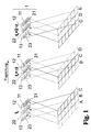
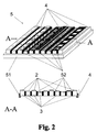
- a filter assembly as in their entirety Fig. 2 is to be explained first - to explain their particular application requirements when used in a multispectral line scan camera (so-called pushbroom scanner).
- the instrument first detects with a sensor line 11 the red spectral components of the ground strip C, which were selected by the red filter 21.
- an adjacent ground strip B is detected by the green filter 22 with the green sensor line 12 and the further ground strip A is detected by the sensor line 13 via the blue filter 23.
- the bottom strip C is detected by the green filter 22 with the sensor line 12.
- a further time interval .DELTA.t that at time t 0 + 2 ⁇ t, the floor strip C is then absorbed by the blue filter 23 coupled to the sensor line.
- ground strip C has been successively recorded by all (here - for simplicity and without restriction of generality - only three) spectral channels, while the other channels (sensor line 11 with filter 12 and sensor line 12 with filter 22) at time t 0 + ⁇ t already record their associated spectral components of the next ground strip C or B and at time t 0 + 2 ⁇ t the ground strips D and C respectively.
- a common imaging optics and sensor lines 11, 12, 13 etc. integrated on a chip are to be used for the spectrally selective recording of a ground strip A, B, C, D, in the case of the strip-shaped design the multispectral filter assembly 2 particularly narrow filter elements 4 required.
- the risk increases, the already expensive-produced large-area filter substrates when they are separated into narrow bars to damage (additional risk of breakage in addition to the above-mentioned contamination problems).
- the substrate bars 3 required for the filter elements 4 are brought to the required final dimension before the coating.
- suitable processing methods both by molding processes, such as casting, hot working, etc., as well as separation methods, such as sawing, breaking, etc., and then grinding and polishing ) are brought into the desired shape and dimensions.
- the guaranteed dimensionally stable substrate ingots 3 are coated individually or, in order to minimize the risk of the coating process, at the same time in larger quantities with the corresponding spectral filters 2.
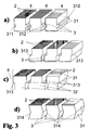
- These spectral filters 2 can be used both on the top, the bottom (as in Fig. 4a shown) or on both sides of the substrate ingot 3 (as in FIG 4b to be isolated).
- a mechanical profiling (grooves, steps, etc.) take place at the joining surfaces 31.
- the joining surfaces 31 have in one embodiment according to Fig. 3a corresponding groove 311 and spring 312, whereby only a single circumferential outer frame 51 is required in the final assembling.
- the joining surfaces 31 can be glued together.
- an optical barrier layer 52 for separating the spectral channels is to be introduced, as in FIG Fig. 2 shown.
- the barrier layer 52 can be performed in the form of a dark pigmented adhesive when desired bonding and thus combined with fixing function, as in Fig. 4a and 4b drawn stylized.
- Fig. 3b an embodiment is shown which has an adapted step shape 313, which - with fixed predetermined spectral order of the different filter elements 4 within the filter assembly 5 - as an alternately shaped T-profile 32 of the individual substrate bars 3 according to Fig. 3c can be executed.
- three-dimensional frames 51 are required in the final assembling at least up to a possibly provided bonding.
- specified self-aligning wedge shape 315 may - similar to the application of grooves 311 and springs 312 - provided for the assembly of the filter assembly 5 frame 51 for adjusting and fixing be limited to a circumferential outer ring.
- the successive (multiple) coating of the substrate for the production of filter elements 4 of the same spectral properties can be done both on individual substrate bars 3 and on a package composite, which is temporarily assembled from a plurality of identical substrate bars 3.
- the latter is particularly indicated when a large number of identical filter elements 4 has to be produced in order to achieve high quality requirements in the subsequent selection step those filter elements 4 with sufficient quality of their spectral properties (such as compliance with the spectral bandwidth of the filter 2 and consistency of the filter properties over the full length of the substrate bar 3).
- positioning aids such as tongue and groove 311 or 312, for example, are provided on the intended joining surfaces 31 (FIG. Fig. 3a ), Steps 313 ( Fig. 3b ) or self-centering wedges 314 ( Fig. 3d ), which are produced without any problems in the production of the uncoated substrate ingots 3 without any problems, so that the final assembly ( Fig. 5 ) of the filter assemblies 5 is simplified and reduce the manufacturing tolerances.
- the variant with steps 313 in the manner according to Fig. 3c be modified by the substrate bars 3 are formed for adjacent different filter elements 4 as T-profiles 32 which are arranged alternately upright and inverted.
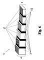
- the substrate bars 3 for different spectral filter elements 4 are manufactured in different substrate thicknesses to compensate for spectral aberrations of the common imaging optics of the (multispectral) line scan 1 to equalize the spectrally different optical path lengths equal in the filter assembly 5.
- An otherwise required separate correction plate is thereby eliminated.
- Fig. 6 shows the appearance the filter assembly 5 with adapted, different high filter elements 4 after assembling.
- substrate bars 3 with suitably adapted shape and different dimensions can be produced.
- Such an embodiment of the invention shows Fig. 7 .
- the different shaping which is possible both in the longitudinal direction of the substrate bar 3 and in the direction orthogonal thereto, is based on the wavelength-dependent distortions and imaging errors.
Landscapes
- Physics & Mathematics (AREA)
- Spectroscopy & Molecular Physics (AREA)
- General Physics & Mathematics (AREA)
- Optics & Photonics (AREA)
- Investigating Or Analysing Materials By Optical Means (AREA)
- Optical Filters (AREA)
- Spectrometry And Color Measurement (AREA)
Applications Claiming Priority (1)
| Application Number | Priority Date | Filing Date | Title |
|---|---|---|---|
| DE102007011112.8A DE102007011112B4 (de) | 2007-03-03 | 2007-03-03 | Verfahren zur Herstellung multispektraler Filterbaugruppen sowie eine multispektrale Filteranordnung |
Publications (2)
| Publication Number | Publication Date |
|---|---|
| EP1967890A2 true EP1967890A2 (fr) | 2008-09-10 |
| EP1967890A3 EP1967890A3 (fr) | 2010-11-17 |
Family
ID=39431107
Family Applications (1)
| Application Number | Title | Priority Date | Filing Date |
|---|---|---|---|
| EP08003762A Ceased EP1967890A3 (fr) | 2007-03-03 | 2008-02-29 | Procédé de fabrication de composants de filtres multispectraux et agencement de filtre multispectral |
Country Status (2)
| Country | Link |
|---|---|
| EP (1) | EP1967890A3 (fr) |
| DE (1) | DE102007011112B4 (fr) |
Cited By (2)
| Publication number | Priority date | Publication date | Assignee | Title |
|---|---|---|---|---|
| WO2011064403A1 (fr) * | 2009-11-30 | 2011-06-03 | Imec | Circuit intégré pour système d'imagerie spectrale |
| FR3053478A1 (fr) * | 2016-07-01 | 2018-01-05 | Sodern | Composant optique passif pour module de detection et procede de fabrication |
Families Citing this family (1)
| Publication number | Priority date | Publication date | Assignee | Title |
|---|---|---|---|---|
| CN113720808B (zh) * | 2021-08-31 | 2024-02-06 | 中国科学院合肥物质科学研究院 | 一种多元光学元件设计方法及多元光学元件 |
Citations (1)
| Publication number | Priority date | Publication date | Assignee | Title |
|---|---|---|---|---|
| US4740059A (en) * | 1983-12-23 | 1988-04-26 | Birger Boldt | Method and apparatus for color synthesis |
Family Cites Families (5)
| Publication number | Priority date | Publication date | Assignee | Title |
|---|---|---|---|---|
| US5073008A (en) * | 1987-12-11 | 1991-12-17 | Fuji Photo Film Co., Ltd. | Multicolor interference filters with side surfaces to prevent entry of undesirable light |
| US7038191B2 (en) * | 2003-03-13 | 2006-05-02 | The Boeing Company | Remote sensing apparatus and method |
| TWI242684B (en) * | 2004-01-30 | 2005-11-01 | Asia Optical Co Inc | Color wheel capable of preventing filter from escape |
| TW200613770A (en) * | 2004-10-26 | 2006-05-01 | Delta Electronics Inc | Color wheel |
| WO2008012706A2 (fr) * | 2006-07-20 | 2008-01-31 | Koninklijke Philips Electronics N.V. | Biocapteur multicolore |
-
2007
- 2007-03-03 DE DE102007011112.8A patent/DE102007011112B4/de not_active Expired - Fee Related
-
2008
- 2008-02-29 EP EP08003762A patent/EP1967890A3/fr not_active Ceased
Patent Citations (1)
| Publication number | Priority date | Publication date | Assignee | Title |
|---|---|---|---|---|
| US4740059A (en) * | 1983-12-23 | 1988-04-26 | Birger Boldt | Method and apparatus for color synthesis |
Cited By (13)
| Publication number | Priority date | Publication date | Assignee | Title |
|---|---|---|---|---|
| US10620049B2 (en) | 2009-11-30 | 2020-04-14 | Imec | Integrated circuit for spectral imaging system |
| CN102741671A (zh) * | 2009-11-30 | 2012-10-17 | Imec公司 | 用于光谱成像系统的集成电路 |
| EP2511681A3 (fr) * | 2009-11-30 | 2012-10-31 | Imec | Circuit intégré pour système d'imagerie spectrale |
| EP2522968A1 (fr) * | 2009-11-30 | 2012-11-14 | Imec | Circuit intégré pour système d'imagerie spectrale |
| US9304039B2 (en) | 2009-11-30 | 2016-04-05 | Imec | Integrated circuit for spectral imaging system |
| CN102741671B (zh) * | 2009-11-30 | 2016-07-06 | Imec公司 | 用于光谱成像系统的集成电路 |
| US10139280B2 (en) | 2009-11-30 | 2018-11-27 | Imec | Integrated circuit for spectral imaging system |
| US10260945B2 (en) | 2009-11-30 | 2019-04-16 | Imec | Integrated circuit for spectral imaging system |
| WO2011064403A1 (fr) * | 2009-11-30 | 2011-06-03 | Imec | Circuit intégré pour système d'imagerie spectrale |
| US11029207B2 (en) | 2009-11-30 | 2021-06-08 | Imec | Integrated circuit for spectral imaging system |
| EP4137790A1 (fr) * | 2009-11-30 | 2023-02-22 | Imec VZW | Circuit intégré pour système d'imagerie spectrale |
| US11733095B2 (en) | 2009-11-30 | 2023-08-22 | Imec | Hyperspectral image sensor with calibration |
| FR3053478A1 (fr) * | 2016-07-01 | 2018-01-05 | Sodern | Composant optique passif pour module de detection et procede de fabrication |
Also Published As
| Publication number | Publication date |
|---|---|
| EP1967890A3 (fr) | 2010-11-17 |
| DE102007011112B4 (de) | 2014-10-02 |
| DE102007011112A1 (de) | 2008-09-04 |
Similar Documents
| Publication | Publication Date | Title |
|---|---|---|
| EP2622314B1 (fr) | Système de prise de vues numérique multispectrale ayant au moins deux appareils de prise de vues numériques indépendants | |
| EP2987028B1 (fr) | Ajustage d'un ensemble de cameras, ensemble de cameras et gabarit pour ajustement | |
| DE3711628C2 (de) | Bildaufnahmevorrichtung | |
| EP1783468B1 (fr) | Procédé d'analyse de spectres d'échelles | |
| DE102013226789B4 (de) | Mehrkanaloptik-Bildaufnahmevorrichtung und Mehrkanaloptik-Bildaufnahmeverfahren | |
| DE69215196T2 (de) | Schirmeinheit für ein Durchsichtprojektionssystem und Verfahren zu ihrer Herstellung | |
| DE69114350T2 (de) | Strahlteilungs-/-vereinigungsvorrichtung. | |
| DE3832658C2 (fr) | ||
| DE102010031535A1 (de) | Bildaufnahmevorrichtung und Verfahren zum Aufnehmen eines Bildes | |
| EP2519852B1 (fr) | Module caméra avec distance focale commutable | |
| DE102007011112B4 (de) | Verfahren zur Herstellung multispektraler Filterbaugruppen sowie eine multispektrale Filteranordnung | |
| DE19620807A1 (de) | Festkörperdetektor | |
| DE102016225097A1 (de) | Optisches System für ein seitwärts blickendes Endoskop sowie seitwärts blickendes Endoskop | |
| DE112004002901B4 (de) | Abbildungsvorrichtung unter Verwendung eines Festkörper-Bildaufnahmeelements | |
| WO2014135391A1 (fr) | Système de caméras pour prises de vues panoramiques | |
| DE20080076U1 (de) | Photogrammetrische Kamera | |
| DE102007036067B4 (de) | Abbildendes Spektrometer, insbesondere für die optische Fernerkundung | |
| DE60013622T2 (de) | Bildaufnahemvorrichtung | |
| DE3927158C2 (fr) | ||
| EP4351159B1 (fr) | Capteur d'image | |
| WO2015032392A2 (fr) | Corps de base optique pour spectromètre, procédé de réalisation de corps de base optique pour spectromètre et spectromètre comprenant un tel corps de base optique | |
| EP1315017A2 (fr) | Elément optique et méthode de fabrication | |
| DE29520865U1 (de) | CCD-Flächensensoren mit Farbmosaik-Filter | |
| DE102009000001B4 (de) | Bildsensor und Verfahren zur Herstellung eines Bildsensors | |
| DE29906678U1 (de) | Spektrometer |
Legal Events
| Date | Code | Title | Description |
|---|---|---|---|
| PUAI | Public reference made under article 153(3) epc to a published international application that has entered the european phase |
Free format text: ORIGINAL CODE: 0009012 |
|
| AK | Designated contracting states |
Kind code of ref document: A2 Designated state(s): AT BE BG CH CY CZ DE DK EE ES FI FR GB GR HR HU IE IS IT LI LT LU LV MC MT NL NO PL PT RO SE SI SK TR |
|
| AX | Request for extension of the european patent |
Extension state: AL BA MK RS |
|
| PUAL | Search report despatched |
Free format text: ORIGINAL CODE: 0009013 |
|
| AK | Designated contracting states |
Kind code of ref document: A3 Designated state(s): AT BE BG CH CY CZ DE DK EE ES FI FR GB GR HR HU IE IS IT LI LT LU LV MC MT NL NO PL PT RO SE SI SK TR |
|
| AX | Request for extension of the european patent |
Extension state: AL BA MK RS |
|
| 17P | Request for examination filed |
Effective date: 20110506 |
|
| AKX | Designation fees paid |
Designated state(s): AT BE BG CH CY CZ DE DK EE ES FI FR GB GR HR HU IE IS IT LI LT LU LV MC MT NL NO PL PT RO SE SI SK TR |
|
| 17Q | First examination report despatched |
Effective date: 20120111 |
|
| STAA | Information on the status of an ep patent application or granted ep patent |
Free format text: STATUS: THE APPLICATION HAS BEEN REFUSED |
|
| 18R | Application refused |
Effective date: 20130920 |