EP1968033B1 - Anzeigevorrichtung mit Halteelement - Google Patents
Anzeigevorrichtung mit Halteelement Download PDFInfo
- Publication number
- EP1968033B1 EP1968033B1 EP07117879A EP07117879A EP1968033B1 EP 1968033 B1 EP1968033 B1 EP 1968033B1 EP 07117879 A EP07117879 A EP 07117879A EP 07117879 A EP07117879 A EP 07117879A EP 1968033 B1 EP1968033 B1 EP 1968033B1
- Authority
- EP
- European Patent Office
- Prior art keywords
- display
- elements
- holder
- display device
- display elements
- Prior art date
- Legal status (The legal status is an assumption and is not a legal conclusion. Google has not performed a legal analysis and makes no representation as to the accuracy of the status listed.)
- Active
Links
Images

Classifications
-
- G—PHYSICS
- G09—EDUCATION; CRYPTOGRAPHY; DISPLAY; ADVERTISING; SEALS
- G09F—DISPLAYING; ADVERTISING; SIGNS; LABELS OR NAME-PLATES; SEALS
- G09F9/00—Indicating arrangements for variable information in which the information is built-up on a support by selection or combination of individual elements
- G09F9/30—Indicating arrangements for variable information in which the information is built-up on a support by selection or combination of individual elements in which the desired character or characters are formed by combining individual elements
- G09F9/302—Indicating arrangements for variable information in which the information is built-up on a support by selection or combination of individual elements in which the desired character or characters are formed by combining individual elements characterised by the form or geometrical disposition of the individual elements
- G09F9/3026—Video wall, i.e. stackable semiconductor matrix display modules
-
- G—PHYSICS
- G09—EDUCATION; CRYPTOGRAPHY; DISPLAY; ADVERTISING; SEALS
- G09F—DISPLAYING; ADVERTISING; SIGNS; LABELS OR NAME-PLATES; SEALS
- G09F9/00—Indicating arrangements for variable information in which the information is built-up on a support by selection or combination of individual elements
- G09F9/30—Indicating arrangements for variable information in which the information is built-up on a support by selection or combination of individual elements in which the desired character or characters are formed by combining individual elements
-
- G—PHYSICS
- G09—EDUCATION; CRYPTOGRAPHY; DISPLAY; ADVERTISING; SEALS
- G09F—DISPLAYING; ADVERTISING; SIGNS; LABELS OR NAME-PLATES; SEALS
- G09F9/00—Indicating arrangements for variable information in which the information is built-up on a support by selection or combination of individual elements
- G09F9/30—Indicating arrangements for variable information in which the information is built-up on a support by selection or combination of individual elements in which the desired character or characters are formed by combining individual elements
- G09F9/33—Indicating arrangements for variable information in which the information is built-up on a support by selection or combination of individual elements in which the desired character or characters are formed by combining individual elements being semiconductor devices, e.g. diodes
Definitions
- the invention relates to a display device for the presentation of optical content, as used in particular at major events.
- Such display devices are usually designed as LED display surfaces.
- a multiplicity of LEDs are arranged parallel to one another in a plurality of mostly vertically extending rows.
- a representation of the optical content is achieved by a targeted control of the individual LEDs.
- EP 1 293 955 describes a display device with a plurality of LED tubes, wherein a certain number of LED tubes are each combined into display panels. These display panels have along their entire circumference a frame construction in which the LED tubes are held. The frame construction further serves to receive a controller for the display device. Depending on the position of the individual display panel in the entire display device, the frame construction of the panel has hinge elements by which the individual display panels are connected to one another via their respective frame. This makes it possible to easily arrange a multiplicity of display panels one above the other or next to one another, so that the display device can take various forms.
- a disadvantage of such a display device is that the display device can not assume any geometric shape. So the outer contour of the display device can only be changed as far as the size of the frame structures of the display panels allowed. Since it is not sensible from the point of view of cost as well as construction-related aspects to provide a large number of display panels with very small frame constructions, the described display device can be adapted only very limited to environmental requirements or to design requirements.
- the object of the invention is to provide a display device that can be easily adapted to the environmental situation or in terms of design aspects.
- U 2002/0126064 describes a display device, wherein a plurality of LED tubes are held in a holding device.
- the holding device consists of a plurality of holding elements which are interconnected by connecting elements.
- the retaining elements are in this case pushed into recesses of the connecting elements, so that a rigid connection of the individual holding elements is formed to each other.
- the entire holding device thus forms a straight line.
- the display elements are held on one side on the holding device.
- a display device for the presentation of optical content, especially at major events has a holding device and a plurality of rod-shaped display elements.
- the display elements have a plurality of bulbs, which may be formed, for example, as LEDs or LED clusters.
- the rod-shaped display elements may be formed as transparent tubes, within which the bulbs are arranged. The display elements are held by the holding device.
- a display area for presenting the optical contents is formed.
- the holding device has a plurality of holding elements, which are interconnected by connecting devices, such as by connecting joints, such that the holding device is variable in shape.
- the holding device does not have to run straight, but may for example have a serpentine course.
- the shape of the display area formed by the display elements is also changeable.
- An essential feature of the invention is that the rod-shaped display elements are held exclusively at a first end of the display elements of the holding device. For example, it is possible that the holding device in the direction of gravity above the display elements is arranged so that the display elements are suspended from the holding device.
- an LED curtain can be designed, which has a non-uniform shape and thus can be adapted to different environmental situations, It is also possible to make the display device in terms of design aspects very flexible.
- the holding device has a plurality of holding elements, which are connected to one another in an articulated manner, for example, so that the holding device does not have to be a straight carrier rail. Rather, the holding device may have a chain-like structure, wherein the individual holding elements are formed as links of the chain.
- the holding device is designed as a multi-member support strut, wherein the individual members of the support strut are formed by the holding elements.
- a display element segment may be formed, for example, as a transparent support tube in which a plurality of LEDs are arranged one behind the other on a circuit board.
- At the ends of the display element segments are preferably plug-in devices for releasable electrical and / or mechanical connection of the display element segments together. This makes it possible to connect the display element segments in a simple manner with each other, this connection can be made very quickly and released again.
- the holding device is arranged exclusively on a first side of the display elements, which is located at the first end of the rod-shaped display elements.
- the holding device is not a frame construction that encompasses the display elements along their entire circumference.
- the holding device is arranged only on a single side of the display elements, wherein the three other sides of the display elements have no holding device. If the holding device is arranged, for example, above the display elements, no further holding device is provided on the left and right as well as on the lower side of the display element.
- a display device over previously known frame structures on a simplified structure. In order to provide a particularly high display device, it is not necessary to connect several frame structures one above the other.
- the connecting devices for connecting the plurality of holding elements are designed as connecting joints.
- the connecting devices may have first and second connection lugs, which are designed in particular as part of the holding elements.
- the holding device may have an overlapping section in the connecting region of two adjacent holding elements, in which the second connecting projection of a first holding element and the first connecting projection of a second holding element overlap.
- the Connecting joint can be formed by the second connection lug of the first holding element and the first connection lug of the second holding element.
- the chain link-like holding elements are mutually pivotable about a plurality of mutually parallel vertical or horizontal axes.
- the holding device according to a chain assume any geometric shape.
- a change in the shape of the display area of the display device takes place at the same time.
- the display elements which are held in the holding device to each other at a constant distance.
- the distance between two adjacent display elements, which are held by different holding elements also equal to the distance between the other display elements with each other.
- a locking device may be provided which is formed in particular by a first locking element on the holding device and by a second locking element on the support elements of the display elements.
- the first and the second latching element act together to hold the display elements.
- the latching device may in particular be six-pole XLR connections.
- the locking device may, in particular at the same time for the electrical and mechanical connection of the display elements, be formed with the holding device.
- the holding device has a power supply device and / or a control device for the display elements. These devices may for example be housed in a housing having the holding device.
- the holding device can also be arranged in the direction of gravity below the display elements, so that the display elements are placed in the holding device.
- the holding device may have a fastening device for connecting the holding device to a carrier device, in particular with a suspension device.
- the suspension device can be, for example, a frame construction on a stage.
- the fastening device may be formed as a clamp, which engages around the frame structure, so that the holding device is firmly connected to the suspension device, in particular to the frame construction.
- the fastening device is designed such that individual holding elements can be removed, for example, for maintenance purposes easily and quickly.
- the lighting means for example the LEDs on a circuit board of the display elements
- the board between two adjacent bulbs can be severed, so that the individual display elements or the individual display element segments are variable in their length.
- a plug-in device can be provided for releasable electrical and / or mechanical connection to an adjacent display element segment, wherein the uniform distances between the lamps remain unchanged relative to one another.
- a background material for example a fabric tarpaulin, which differs from the ones shown in FIG Viewers can be viewed through the display elements.
- a background material fastening elements may be provided on the holding device.
- An independent invention relates to a display device for the presentation of optical contents with a plurality of display elements, wherein a first display area is formed by a first side of the display elements and a second display area by a second side of the display elements.
- display elements having a circuit board, on the front side of which first lighting means, such as LEDs, are mounted, which form a display area which can be viewed from a first direction.
- first lighting means such as LEDs
- further bulbs may be mounted which form a second display area that can be viewed from a second direction opposite to the first direction.
- the light sources on the first side of the board may display the same contents as the light sources on the opposite side of the board.
- the bulbs on the first page display other content than the bulbs on the opposite side of the board.
- the display device centrally in a room, so that it can be viewed from several directions.
- a three-dimensional design effect can be achieved by such a display device.
- such a display device can be viewed by a larger number of viewers without having to increase the dimensions of the display device.
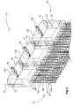
- a display device 10 for presenting optical contents has a holding device 12 and a plurality of bar-shaped display elements 14.
- the display elements 14 have a plurality of LEDs 16 which are arranged in parallel rows to each other.
- the display elements 14 are held by the holding device 12 such that a display area for presenting the optical contents is formed by the plurality of parallel display elements 14.
- the holding device 12 has a plurality of holding elements 12a, 12b, 12c, which are connected to one another by connecting joints 20 such that the holding device 12 can be changed in its shape.
- the connecting joints 20 are formed by a second connecting lug 20b of a first holding element 12a and by a first connecting lug 20a of a second holding element 12b, wherein the two holding elements 12a, 12b are arranged adjacent to one another.
- the connecting joints 20 extends an actual or virtual axis 22 about which the adjacent holding elements 12a, 12b are mutually pivotable.
- the axis 22 extends in a vertical direction, ie parallel to the direction of gravity 34th
- the display elements 14 are held exclusively at a first end of the display elements 14 of the holding device 12. In the illustrated exemplary embodiments, this is the direction of gravity 34 upper end of the display elements 14. The display elements 14 are thus suspended in the holding device 12 and in particular in the holding elements 12a, 12b, 12c.
- the chain link-like holding elements 12a, 12b, 12c are mutually pivotable about a plurality of mutually parallel vertical axes 22.
- the display elements 14 are further held by a latching device 24 in the holding device 12, wherein the latching device is formed by a first latching element 24a on the holding device 12 and by a second latching element 24b on the transparent tubular support elements 26.
- the locking device 24 is preferably an XLR connection.
- a plurality of LEDs 16 may be arranged side by side in a tubular carrier element 26, wherein the plurality of juxtaposed LEDs 16 may be controlled individually or jointly and thus form an LED cluster.
- a luminous means, such as an LED 16 may comprise three individual LEDs which are operated, for example, according to the RGB principle.
- the holding device 12 has a power supply device 28 and a control device 30 for the display elements 14. These devices are arranged within a housing 32 of the holding device 12.
- the connecting lugs 20a, 20b may have a different height.
- the connection lug 20b which is arranged on the side of the holding device 12, on which the display elements 14 are held, has a lower height than the connecting projection 20a provided on the opposite side. This can ensure that possible movements of the display elements, the caused by external forces are not introduced by an excessive lever in the holding device 12.
- a holding element 12a, 12b, 12c on its upper side on a web 21 which has a bore through which, for example, a screw can be passed.
- This screw can be screwed into a nut integrated into the connecting lug 20b, so that it assumes the function of the pivot axis 22.
- the holding elements 12a, 12b, 12c can have recesses 23 on their sides, through which, for example, control or voltage supply lines can be passed from one holding element 12a to the next holding element 12b.
- the individual holding elements 12a, 12b, 12c can be electrically connected to one another in a simple manner.
- the recesses 23 are preferably formed in the region of the connecting joints 20.
- the holding elements 12a, 12b, 12c may further have ventilation grids 25 at any point.
- Fig. 1 is a fastening device 36 for connecting the holding device 12 with a suspension device, not shown, for example, with a scaffold on a stage provided.
- the display elements 14 have a plurality of display element segments 14a, 14b arranged one behind the other, wherein a display element 14 is formed by a plurality of display element segments 14a, 14b arranged one behind the other.
- plug devices 38 for releasable electrical and / or mechanical connection of the display element segments 14a, 14b are provided together. In each case, two adjacent display element segments 14a, 14b are interconnected.
- the lighting means 16 of the display elements 14 are mounted on a circuit board 40 which may be disposed within a tubular support column 26 made of plastic.
- the bulbs 16 have on the board 40 at regular intervals to each other. Between two adjacent bulbs 16, the board 40 can be severed, for example, with a saw, so that the display elements 14 are variable in length. For example, an approximately 2 cm long piece of the board 40 can be separated and in its place a plug-in device 38 for releasable electrical connection to a further adjacent display element segment 14a, 14b are provided. The uniform distances between the lamps 16 remain unchanged.
- the board 40 may also have more or fewer than six parallel lines.
- the mechanical connection of two adjacent display element segments 14a, 14b can be produced by a, not shown, short, transparent adapter piece which is formed in the same way as the tubular support elements 26.
- This adapter piece may for example have a slightly larger diameter than the tubular support elements 26, so that it can be arranged between two adjacent support members 26 such that the support members 26 can be inserted on both sides of the adapter piece in this.
- a fixed mechanical connection between the support members 26 and the adapter piece can be made for example by screws. It is also possible to produce the connection by means of a spring-loaded snap lock, for example, which can be mounted on a carrier element 26 and which engages in a recess provided for this purpose on the edge of the adapter piece.
- the board 40 has at regular intervals holes in the example, screws for mechanical attachment of the board 40 can be screwed to the support members 26. It is particularly preferred to arrange these holes at the locations of the board at which the board, as shown above, can be severed to change its length.
- all embodiments of the invention may comprise a spacer element 50, by which the tubular carrier elements 26 are connected to each other, so that the display elements 14, which are preferably parallel, always have a constant spacing from top to bottom.
- FIG. 4 An independent invention is in Fig. 4 shown.
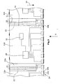
- a display device 10 for the presentation of optical contents with a plurality of display elements 14, which in Fig. 4 are arranged side by side perpendicular to the sheet direction.
- the holding device 12 runs according to Fig. 4 also perpendicular to the sheet direction.
- tubular support members 26 within which a circuit board 40 is formed.
- bulbs 16, which are formed as LEDs are formed as LEDs.
- the LEDs 16 on the first side of the display elements 14 form a first display area 42.
- the LEDs 16 on the second side of the display elements 14 form a second display area 44.
- the first display area 42 can be viewed from a first direction 46.
- the second display area 44 may be viewed from a second direction 48 that is opposite to the first direction 46.
Landscapes
- Engineering & Computer Science (AREA)
- Physics & Mathematics (AREA)
- General Physics & Mathematics (AREA)
- Theoretical Computer Science (AREA)
- Multimedia (AREA)
- Devices For Indicating Variable Information By Combining Individual Elements (AREA)
- Led Device Packages (AREA)
- Push-Button Switches (AREA)
- Liquid Crystal (AREA)
- Input Circuits Of Receivers And Coupling Of Receivers And Audio Equipment (AREA)
- Measuring Pulse, Heart Rate, Blood Pressure Or Blood Flow (AREA)
- Devices For Checking Fares Or Tickets At Control Points (AREA)
Priority Applications (1)
| Application Number | Priority Date | Filing Date | Title |
|---|---|---|---|
| PL07117879T PL1968033T3 (pl) | 2007-03-09 | 2007-10-04 | Urządzenie wyświetlające z elementem uchwytowym |
Applications Claiming Priority (1)
| Application Number | Priority Date | Filing Date | Title |
|---|---|---|---|
| DE102007011986A DE102007011986A1 (de) | 2007-03-09 | 2007-03-09 | Anzeigevorrichtung mit Halteelement |
Publications (2)
| Publication Number | Publication Date |
|---|---|
| EP1968033A1 EP1968033A1 (de) | 2008-09-10 |
| EP1968033B1 true EP1968033B1 (de) | 2009-10-21 |
Family
ID=39201962
Family Applications (1)
| Application Number | Title | Priority Date | Filing Date |
|---|---|---|---|
| EP07117879A Active EP1968033B1 (de) | 2007-03-09 | 2007-10-04 | Anzeigevorrichtung mit Halteelement |
Country Status (8)
| Country | Link |
|---|---|
| US (1) | US7852285B2 (da) |
| EP (1) | EP1968033B1 (da) |
| AT (1) | ATE446567T1 (da) |
| DE (2) | DE102007011986A1 (da) |
| DK (1) | DK1968033T3 (da) |
| ES (1) | ES2334521T3 (da) |
| PL (1) | PL1968033T3 (da) |
| PT (1) | PT1968033E (da) |
Families Citing this family (5)
| Publication number | Priority date | Publication date | Assignee | Title |
|---|---|---|---|---|
| DE102008012890B3 (de) * | 2008-03-06 | 2009-08-13 | Thomas Tennagels | Anzeigevorrichtung mit einer Entriegelungsvorrichtung |
| TWM363277U (en) * | 2008-12-02 | 2009-08-21 | Jia-Xiu Lin | LED curtain apparatus |
| WO2013149432A1 (zh) * | 2012-04-05 | 2013-10-10 | 湖南新亚胜科技发展有限公司 | 可快捷安装的多功能显示屏 |
| CN107993581B (zh) * | 2017-11-30 | 2019-12-13 | 武汉天马微电子有限公司 | 一种显示面板及显示装置 |
| KR102494740B1 (ko) * | 2021-03-18 | 2023-02-06 | 김봉준 | 화소별 출몰구조를 갖는 입체 스크린 장치 |
Family Cites Families (6)
| Publication number | Priority date | Publication date | Assignee | Title |
|---|---|---|---|---|
| JP3649492B2 (ja) * | 1995-11-10 | 2005-05-18 | アビックス株式会社 | 自動車道コーナー部の情報表示装置 |
| US20020126064A1 (en) * | 2001-03-07 | 2002-09-12 | Star-Reach Corporation | Matrix type LED wall display tube device |
| JP2003162237A (ja) | 2001-09-14 | 2003-06-06 | Kasuto:Kk | 表示装置 |
| US7158020B2 (en) * | 2002-09-10 | 2007-01-02 | Grady Jr James A | LED warning beacon |
| ES2261018B1 (es) * | 2004-07-05 | 2007-08-01 | Universidad De Malaga | Sistema modular para la iluminacion homogenea de mobiliario urbano con diodos leds. |
| DE202004014145U1 (de) * | 2004-09-09 | 2005-10-27 | G-Lec Europe Gmbh | Anzeigevorrichtung |
-
2007
- 2007-03-09 DE DE102007011986A patent/DE102007011986A1/de not_active Ceased
- 2007-10-04 EP EP07117879A patent/EP1968033B1/de active Active
- 2007-10-04 AT AT07117879T patent/ATE446567T1/de active
- 2007-10-04 DE DE502007001789T patent/DE502007001789D1/de active Active
- 2007-10-04 ES ES07117879T patent/ES2334521T3/es active Active
- 2007-10-04 DK DK07117879.2T patent/DK1968033T3/da active
- 2007-10-04 PL PL07117879T patent/PL1968033T3/pl unknown
- 2007-10-04 PT PT07117879T patent/PT1968033E/pt unknown
-
2008
- 2008-03-04 US US12/074,484 patent/US7852285B2/en not_active Expired - Fee Related
Also Published As
| Publication number | Publication date |
|---|---|
| ATE446567T1 (de) | 2009-11-15 |
| ES2334521T3 (es) | 2010-03-11 |
| DE502007001789D1 (de) | 2009-12-03 |
| DK1968033T3 (da) | 2010-03-01 |
| DE102007011986A1 (de) | 2008-09-11 |
| US20080218370A1 (en) | 2008-09-11 |
| EP1968033A1 (de) | 2008-09-10 |
| US7852285B2 (en) | 2010-12-14 |
| PT1968033E (pt) | 2010-01-07 |
| PL1968033T3 (pl) | 2010-03-31 |
Similar Documents
| Publication | Publication Date | Title |
|---|---|---|
| DE102011085291B4 (de) | Lichtbeeinflussungselement zur Beeinflussung der Lichtabgabe von im Wesentlichen punktförmigen Lichtquellen | |
| DE102015114814B4 (de) | System aus Steckverbinder-Modulrahmen und Adapterelementen sowie modularen Steckverbinder mit einem solchen System | |
| DE202013103611U1 (de) | Halterahmen für Steckverbinder | |
| DE1590197A1 (de) | Flaechig ausgebildeter isolierter Anschlussteil | |
| EP1968033B1 (de) | Anzeigevorrichtung mit Halteelement | |
| EP1847763A1 (de) | Mehrseitige Beleuchtungsanordnung mit Entblendung | |
| EP3165821B1 (de) | Längliches lichtbandelement | |
| EP2485347A2 (de) | Vorrichtung zur Positionierung wenigstens eines Rundsteckers | |
| EP0795719B1 (de) | Modular aufgebaute Leuchteneinheit | |
| EP0982537A2 (de) | Scherengitterleuchte | |
| EP3461963A1 (de) | Trägersystem und system von verbindungselementen zur verbindung von trägern | |
| EP2446777B1 (de) | Knotenbauteil für ein Gestell für einen Tisch, Gestell für einen Tisch sowie Tisch | |
| DE102017124853A1 (de) | Optisches System für eine LED-Leuchte | |
| DE2648661B2 (de) | Haltevorrichtung für mit einem Stecker versehbare Leiterplatten o.dgl. Bauteile elektromechanischer Bauelemente | |
| DE2020628C3 (de) | System zur Anordnung und Befestigung von Anzeige- und Bedienungselementen in Baueinheiten der Meß-, Steuer- und Regeltechnik | |
| DE102015226704B4 (de) | Gehäuse, Verbinder und System | |
| DE1905735A1 (de) | Abhaengbare Deckenkonstruktion | |
| DE19917015B4 (de) | Stützfuß für einen Schutzzaun aus Profilstäben | |
| EP2469162B1 (de) | Haltevorrichtung für eine Leuchte | |
| DE20019792U1 (de) | Steckverbinder-Gehäuse mit Kodiereinrichtung | |
| DE102020119666B3 (de) | Winkelschiene und Vorsatzanordnung hiermit | |
| DE4293421C2 (de) | Steckervorrichtung für ein Kabel | |
| DE4240220A1 (en) | LV electrical power supply rail - has body of insulating material with recesses to receive conductor tubes and latching elements for outer conductors | |
| DE29620441U1 (de) | Gerüst für einen Schaltschrank | |
| DE3229581A1 (de) | Wand- oder deckenverkleidung |
Legal Events
| Date | Code | Title | Description |
|---|---|---|---|
| PUAI | Public reference made under article 153(3) epc to a published international application that has entered the european phase |
Free format text: ORIGINAL CODE: 0009012 |
|
| AK | Designated contracting states |
Kind code of ref document: A1 Designated state(s): AT BE BG CH CY CZ DE DK EE ES FI FR GB GR HU IE IS IT LI LT LU LV MC MT NL PL PT RO SE SI SK TR |
|
| AX | Request for extension of the european patent |
Extension state: AL BA HR MK RS |
|
| 17P | Request for examination filed |
Effective date: 20080912 |
|
| AKX | Designation fees paid |
Designated state(s): AT BE BG CH CY CZ DE DK EE ES FI FR GB GR HU IE IS IT LI LT LU LV MC MT NL PL PT RO SE SI SK TR |
|
| GRAP | Despatch of communication of intention to grant a patent |
Free format text: ORIGINAL CODE: EPIDOSNIGR1 |
|
| GRAS | Grant fee paid |
Free format text: ORIGINAL CODE: EPIDOSNIGR3 |
|
| GRAA | (expected) grant |
Free format text: ORIGINAL CODE: 0009210 |
|
| AK | Designated contracting states |
Kind code of ref document: B1 Designated state(s): AT BE BG CH CY CZ DE DK EE ES FI FR GB GR HU IE IS IT LI LT LU LV MC MT NL PL PT RO SE SI SK TR |
|
| REG | Reference to a national code |
Ref country code: GB Ref legal event code: FG4D Free format text: NOT ENGLISH |
|
| REG | Reference to a national code |
Ref country code: CH Ref legal event code: EP |
|
| REG | Reference to a national code |
Ref country code: IE Ref legal event code: FG4D |
|
| REF | Corresponds to: |
Ref document number: 502007001789 Country of ref document: DE Date of ref document: 20091203 Kind code of ref document: P |
|
| REG | Reference to a national code |
Ref country code: CH Ref legal event code: NV Representative=s name: ISLER & PEDRAZZINI AG |
|
| RAP2 | Party data changed (patent owner data changed or rights of a patent transferred) |
Owner name: TENNAGELS, THOMAS |
|
| RIN2 | Information on inventor provided after grant (corrected) |
Inventor name: TENNAGELS, THOMAS |
|
| REG | Reference to a national code |
Ref country code: PT Ref legal event code: SC4A Free format text: AVAILABILITY OF NATIONAL TRANSLATION Effective date: 20091230 |
|
| NLT2 | Nl: modifications (of names), taken from the european patent patent bulletin |
Owner name: TENNAGELS, THOMAS Effective date: 20091216 |
|
| REG | Reference to a national code |
Ref country code: SE Ref legal event code: TRGR |
|
| REG | Reference to a national code |
Ref country code: GR Ref legal event code: EP Ref document number: 20100400129 Country of ref document: GR |
|
| REG | Reference to a national code |
Ref country code: DK Ref legal event code: T3 |
|
| REG | Reference to a national code |
Ref country code: ES Ref legal event code: FG2A Ref document number: 2334521 Country of ref document: ES Kind code of ref document: T3 |
|
| LTIE | Lt: invalidation of european patent or patent extension |
Effective date: 20091021 |
|
| REG | Reference to a national code |
Ref country code: PL Ref legal event code: T3 |
|
| PG25 | Lapsed in a contracting state [announced via postgrant information from national office to epo] |
Ref country code: IS Free format text: LAPSE BECAUSE OF FAILURE TO SUBMIT A TRANSLATION OF THE DESCRIPTION OR TO PAY THE FEE WITHIN THE PRESCRIBED TIME-LIMIT Effective date: 20100221 Ref country code: LT Free format text: LAPSE BECAUSE OF FAILURE TO SUBMIT A TRANSLATION OF THE DESCRIPTION OR TO PAY THE FEE WITHIN THE PRESCRIBED TIME-LIMIT Effective date: 20091021 |
|
| REG | Reference to a national code |
Ref country code: IE Ref legal event code: FD4D |
|
| PG25 | Lapsed in a contracting state [announced via postgrant information from national office to epo] |
Ref country code: SI Free format text: LAPSE BECAUSE OF FAILURE TO SUBMIT A TRANSLATION OF THE DESCRIPTION OR TO PAY THE FEE WITHIN THE PRESCRIBED TIME-LIMIT Effective date: 20091021 Ref country code: CY Free format text: LAPSE BECAUSE OF FAILURE TO SUBMIT A TRANSLATION OF THE DESCRIPTION OR TO PAY THE FEE WITHIN THE PRESCRIBED TIME-LIMIT Effective date: 20091021 Ref country code: LV Free format text: LAPSE BECAUSE OF FAILURE TO SUBMIT A TRANSLATION OF THE DESCRIPTION OR TO PAY THE FEE WITHIN THE PRESCRIBED TIME-LIMIT Effective date: 20091021 |
|
| PG25 | Lapsed in a contracting state [announced via postgrant information from national office to epo] |
Ref country code: BG Free format text: LAPSE BECAUSE OF FAILURE TO SUBMIT A TRANSLATION OF THE DESCRIPTION OR TO PAY THE FEE WITHIN THE PRESCRIBED TIME-LIMIT Effective date: 20100121 Ref country code: EE Free format text: LAPSE BECAUSE OF FAILURE TO SUBMIT A TRANSLATION OF THE DESCRIPTION OR TO PAY THE FEE WITHIN THE PRESCRIBED TIME-LIMIT Effective date: 20091021 Ref country code: RO Free format text: LAPSE BECAUSE OF FAILURE TO SUBMIT A TRANSLATION OF THE DESCRIPTION OR TO PAY THE FEE WITHIN THE PRESCRIBED TIME-LIMIT Effective date: 20091021 Ref country code: IE Free format text: LAPSE BECAUSE OF FAILURE TO SUBMIT A TRANSLATION OF THE DESCRIPTION OR TO PAY THE FEE WITHIN THE PRESCRIBED TIME-LIMIT Effective date: 20091021 |
|
| PLBE | No opposition filed within time limit |
Free format text: ORIGINAL CODE: 0009261 |
|
| STAA | Information on the status of an ep patent application or granted ep patent |
Free format text: STATUS: NO OPPOSITION FILED WITHIN TIME LIMIT |
|
| PG25 | Lapsed in a contracting state [announced via postgrant information from national office to epo] |
Ref country code: SK Free format text: LAPSE BECAUSE OF FAILURE TO SUBMIT A TRANSLATION OF THE DESCRIPTION OR TO PAY THE FEE WITHIN THE PRESCRIBED TIME-LIMIT Effective date: 20091021 |
|
| 26N | No opposition filed |
Effective date: 20100722 |
|
| PGFP | Annual fee paid to national office [announced via postgrant information from national office to epo] |
Ref country code: PT Payment date: 20100922 Year of fee payment: 4 |
|
| PGFP | Annual fee paid to national office [announced via postgrant information from national office to epo] |
Ref country code: PL Payment date: 20101004 Year of fee payment: 4 |
|
| PGFP | Annual fee paid to national office [announced via postgrant information from national office to epo] |
Ref country code: GR Payment date: 20101020 Year of fee payment: 4 |
|
| PG25 | Lapsed in a contracting state [announced via postgrant information from national office to epo] |
Ref country code: MC Free format text: LAPSE BECAUSE OF NON-PAYMENT OF DUE FEES Effective date: 20101031 |
|
| PG25 | Lapsed in a contracting state [announced via postgrant information from national office to epo] |
Ref country code: IT Free format text: LAPSE BECAUSE OF NON-PAYMENT OF DUE FEES Effective date: 20101004 Ref country code: MT Free format text: LAPSE BECAUSE OF FAILURE TO SUBMIT A TRANSLATION OF THE DESCRIPTION OR TO PAY THE FEE WITHIN THE PRESCRIBED TIME-LIMIT Effective date: 20091021 |
|
| REG | Reference to a national code |
Ref country code: PT Ref legal event code: MM4A Free format text: LAPSE DUE TO NON-PAYMENT OF FEES Effective date: 20120404 |
|
| REG | Reference to a national code |
Ref country code: GR Ref legal event code: ML Ref document number: 20100400129 Country of ref document: GR Effective date: 20120503 |
|
| PG25 | Lapsed in a contracting state [announced via postgrant information from national office to epo] |
Ref country code: GR Free format text: LAPSE BECAUSE OF NON-PAYMENT OF DUE FEES Effective date: 20120503 Ref country code: PT Free format text: LAPSE BECAUSE OF NON-PAYMENT OF DUE FEES Effective date: 20120404 |
|
| PG25 | Lapsed in a contracting state [announced via postgrant information from national office to epo] |
Ref country code: LU Free format text: LAPSE BECAUSE OF NON-PAYMENT OF DUE FEES Effective date: 20101004 Ref country code: HU Free format text: LAPSE BECAUSE OF FAILURE TO SUBMIT A TRANSLATION OF THE DESCRIPTION OR TO PAY THE FEE WITHIN THE PRESCRIBED TIME-LIMIT Effective date: 20100422 |
|
| PGFP | Annual fee paid to national office [announced via postgrant information from national office to epo] |
Ref country code: DK Payment date: 20121025 Year of fee payment: 6 |
|
| PGFP | Annual fee paid to national office [announced via postgrant information from national office to epo] |
Ref country code: CZ Payment date: 20120927 Year of fee payment: 6 Ref country code: FI Payment date: 20121022 Year of fee payment: 6 |
|
| REG | Reference to a national code |
Ref country code: PL Ref legal event code: LAPE |
|
| PG25 | Lapsed in a contracting state [announced via postgrant information from national office to epo] |
Ref country code: PL Free format text: LAPSE BECAUSE OF NON-PAYMENT OF DUE FEES Effective date: 20111004 |
|
| PGFP | Annual fee paid to national office [announced via postgrant information from national office to epo] |
Ref country code: SE Payment date: 20121024 Year of fee payment: 6 |
|
| PG25 | Lapsed in a contracting state [announced via postgrant information from national office to epo] |
Ref country code: CZ Free format text: LAPSE BECAUSE OF NON-PAYMENT OF DUE FEES Effective date: 20131004 |
|
| REG | Reference to a national code |
Ref country code: DK Ref legal event code: EBP Effective date: 20131031 |
|
| REG | Reference to a national code |
Ref country code: SE Ref legal event code: EUG |
|
| PG25 | Lapsed in a contracting state [announced via postgrant information from national office to epo] |
Ref country code: FI Free format text: LAPSE BECAUSE OF NON-PAYMENT OF DUE FEES Effective date: 20131004 Ref country code: SE Free format text: LAPSE BECAUSE OF NON-PAYMENT OF DUE FEES Effective date: 20131005 |
|
| PG25 | Lapsed in a contracting state [announced via postgrant information from national office to epo] |
Ref country code: DK Free format text: LAPSE BECAUSE OF NON-PAYMENT OF DUE FEES Effective date: 20131031 |
|
| PGFP | Annual fee paid to national office [announced via postgrant information from national office to epo] |
Ref country code: CH Payment date: 20141024 Year of fee payment: 8 |
|
| PGFP | Annual fee paid to national office [announced via postgrant information from national office to epo] |
Ref country code: AT Payment date: 20141022 Year of fee payment: 8 Ref country code: NL Payment date: 20141023 Year of fee payment: 8 |
|
| PGFP | Annual fee paid to national office [announced via postgrant information from national office to epo] |
Ref country code: BE Payment date: 20141020 Year of fee payment: 8 |
|
| PGFP | Annual fee paid to national office [announced via postgrant information from national office to epo] |
Ref country code: TR Payment date: 20131004 Year of fee payment: 7 |
|
| REG | Reference to a national code |
Ref country code: FR Ref legal event code: PLFP Year of fee payment: 9 |
|
| REG | Reference to a national code |
Ref country code: CH Ref legal event code: PL |
|
| REG | Reference to a national code |
Ref country code: AT Ref legal event code: MM01 Ref document number: 446567 Country of ref document: AT Kind code of ref document: T Effective date: 20151004 |
|
| REG | Reference to a national code |
Ref country code: NL Ref legal event code: MM Effective date: 20151101 |
|
| PG25 | Lapsed in a contracting state [announced via postgrant information from national office to epo] |
Ref country code: CH Free format text: LAPSE BECAUSE OF NON-PAYMENT OF DUE FEES Effective date: 20151031 Ref country code: LI Free format text: LAPSE BECAUSE OF NON-PAYMENT OF DUE FEES Effective date: 20151031 |
|
| PG25 | Lapsed in a contracting state [announced via postgrant information from national office to epo] |
Ref country code: AT Free format text: LAPSE BECAUSE OF NON-PAYMENT OF DUE FEES Effective date: 20151004 Ref country code: NL Free format text: LAPSE BECAUSE OF NON-PAYMENT OF DUE FEES Effective date: 20151101 |
|
| REG | Reference to a national code |
Ref country code: FR Ref legal event code: PLFP Year of fee payment: 10 |
|
| PG25 | Lapsed in a contracting state [announced via postgrant information from national office to epo] |
Ref country code: BE Free format text: LAPSE BECAUSE OF NON-PAYMENT OF DUE FEES Effective date: 20151031 |
|
| PG25 | Lapsed in a contracting state [announced via postgrant information from national office to epo] |
Ref country code: TR Free format text: LAPSE BECAUSE OF NON-PAYMENT OF DUE FEES Effective date: 20151004 |
|
| REG | Reference to a national code |
Ref country code: FR Ref legal event code: PLFP Year of fee payment: 11 |
|
| REG | Reference to a national code |
Ref country code: FR Ref legal event code: PLFP Year of fee payment: 12 |
|
| PGFP | Annual fee paid to national office [announced via postgrant information from national office to epo] |
Ref country code: IT Payment date: 20221031 Year of fee payment: 16 Ref country code: GB Payment date: 20221024 Year of fee payment: 16 |
|
| GBPC | Gb: european patent ceased through non-payment of renewal fee |
Effective date: 20231004 |
|
| PG25 | Lapsed in a contracting state [announced via postgrant information from national office to epo] |
Ref country code: GB Free format text: LAPSE BECAUSE OF NON-PAYMENT OF DUE FEES Effective date: 20231004 |
|
| PG25 | Lapsed in a contracting state [announced via postgrant information from national office to epo] |
Ref country code: GB Free format text: LAPSE BECAUSE OF NON-PAYMENT OF DUE FEES Effective date: 20231004 |
|
| PG25 | Lapsed in a contracting state [announced via postgrant information from national office to epo] |
Ref country code: IT Free format text: LAPSE BECAUSE OF NON-PAYMENT OF DUE FEES Effective date: 20231004 |
|
| PG25 | Lapsed in a contracting state [announced via postgrant information from national office to epo] |
Ref country code: IT Free format text: LAPSE BECAUSE OF NON-PAYMENT OF DUE FEES Effective date: 20231004 |
|
| PGFP | Annual fee paid to national office [announced via postgrant information from national office to epo] |
Ref country code: FR Payment date: 20241025 Year of fee payment: 18 |
|
| PGFP | Annual fee paid to national office [announced via postgrant information from national office to epo] |
Ref country code: ES Payment date: 20241118 Year of fee payment: 18 |
|
| PGFP | Annual fee paid to national office [announced via postgrant information from national office to epo] |
Ref country code: DE Payment date: 20250915 Year of fee payment: 19 |