EP1968049A1 - Verfahren zur Wiedergabe von Informationen auf einer optischen Scheibe und Vorrichtung zur Abspielung einer optischen Scheibe unter Anwendung dieses Verfahrens - Google Patents
Verfahren zur Wiedergabe von Informationen auf einer optischen Scheibe und Vorrichtung zur Abspielung einer optischen Scheibe unter Anwendung dieses Verfahrens Download PDFInfo
- Publication number
- EP1968049A1 EP1968049A1 EP08100036A EP08100036A EP1968049A1 EP 1968049 A1 EP1968049 A1 EP 1968049A1 EP 08100036 A EP08100036 A EP 08100036A EP 08100036 A EP08100036 A EP 08100036A EP 1968049 A1 EP1968049 A1 EP 1968049A1
- Authority
- EP
- European Patent Office
- Prior art keywords
- optical disc
- optical
- regions
- region
- information
- Prior art date
- Legal status (The legal status is an assumption and is not a legal conclusion. Google has not performed a legal analysis and makes no representation as to the accuracy of the status listed.)
- Ceased
Links
Images


Classifications
-
- G—PHYSICS
- G11—INFORMATION STORAGE
- G11B—INFORMATION STORAGE BASED ON RELATIVE MOVEMENT BETWEEN RECORD CARRIER AND TRANSDUCER
- G11B7/00—Recording or reproducing by optical means, e.g. recording using a thermal beam of optical radiation by modifying optical properties or the physical structure, reproducing using an optical beam at lower power by sensing optical properties; Record carriers therefor
- G11B7/004—Recording, reproducing or erasing methods; Read, write or erase circuits therefor
- G11B7/005—Reproducing
-
- G—PHYSICS
- G11—INFORMATION STORAGE
- G11B—INFORMATION STORAGE BASED ON RELATIVE MOVEMENT BETWEEN RECORD CARRIER AND TRANSDUCER
- G11B7/00—Recording or reproducing by optical means, e.g. recording using a thermal beam of optical radiation by modifying optical properties or the physical structure, reproducing using an optical beam at lower power by sensing optical properties; Record carriers therefor
- G11B7/12—Heads, e.g. forming of the optical beam spot or modulation of the optical beam
- G11B7/135—Means for guiding the beam from the source to the record carrier or from the record carrier to the detector
- G11B7/1372—Lenses
- G11B7/1376—Collimator lenses
-
- G—PHYSICS
- G11—INFORMATION STORAGE
- G11B—INFORMATION STORAGE BASED ON RELATIVE MOVEMENT BETWEEN RECORD CARRIER AND TRANSDUCER
- G11B7/00—Recording or reproducing by optical means, e.g. recording using a thermal beam of optical radiation by modifying optical properties or the physical structure, reproducing using an optical beam at lower power by sensing optical properties; Record carriers therefor
- G11B7/007—Arrangement of the information on the record carrier, e.g. form of tracks, actual track shape, e.g. wobbled, or cross-section, e.g. v-shaped; Sequential information structures, e.g. sectoring or header formats within a track
-
- G—PHYSICS
- G11—INFORMATION STORAGE
- G11B—INFORMATION STORAGE BASED ON RELATIVE MOVEMENT BETWEEN RECORD CARRIER AND TRANSDUCER
- G11B7/00—Recording or reproducing by optical means, e.g. recording using a thermal beam of optical radiation by modifying optical properties or the physical structure, reproducing using an optical beam at lower power by sensing optical properties; Record carriers therefor
- G11B7/007—Arrangement of the information on the record carrier, e.g. form of tracks, actual track shape, e.g. wobbled, or cross-section, e.g. v-shaped; Sequential information structures, e.g. sectoring or header formats within a track
- G11B7/00736—Auxiliary data, e.g. lead-in, lead-out, Power Calibration Area [PCA], Burst Cutting Area [BCA], control information
-
- G—PHYSICS
- G11—INFORMATION STORAGE
- G11B—INFORMATION STORAGE BASED ON RELATIVE MOVEMENT BETWEEN RECORD CARRIER AND TRANSDUCER
- G11B7/00—Recording or reproducing by optical means, e.g. recording using a thermal beam of optical radiation by modifying optical properties or the physical structure, reproducing using an optical beam at lower power by sensing optical properties; Record carriers therefor
- G11B7/007—Arrangement of the information on the record carrier, e.g. form of tracks, actual track shape, e.g. wobbled, or cross-section, e.g. v-shaped; Sequential information structures, e.g. sectoring or header formats within a track
- G11B7/0079—Zoned data area, e.g. having different data structures or formats for the user data within data layer, Zone Constant Linear Velocity [ZCLV], Zone Constant Angular Velocity [ZCAV], carriers with RAM and ROM areas
-
- G—PHYSICS
- G11—INFORMATION STORAGE
- G11B—INFORMATION STORAGE BASED ON RELATIVE MOVEMENT BETWEEN RECORD CARRIER AND TRANSDUCER
- G11B7/00—Recording or reproducing by optical means, e.g. recording using a thermal beam of optical radiation by modifying optical properties or the physical structure, reproducing using an optical beam at lower power by sensing optical properties; Record carriers therefor
- G11B7/24—Record carriers characterised by shape, structure or physical properties, or by the selection of the material
- G11B7/2407—Tracks or pits; Shape, structure or physical properties thereof
- G11B7/24073—Tracks
- G11B7/24079—Width or depth
-
- G—PHYSICS
- G11—INFORMATION STORAGE
- G11B—INFORMATION STORAGE BASED ON RELATIVE MOVEMENT BETWEEN RECORD CARRIER AND TRANSDUCER
- G11B19/00—Driving, starting, stopping record carriers not specifically of filamentary or web form, or of supports therefor; Control thereof; Control of operating function ; Driving both disc and head
- G11B19/02—Control of operating function, e.g. switching from recording to reproducing
- G11B19/12—Control of operating function, e.g. switching from recording to reproducing by sensing distinguishing features of or on records, e.g. diameter end mark
Definitions
- aspects of the present invention relate to a method of reproducing information from an optical disc and an optical disc reproducing apparatus using the same, and more particularly, to a method of reproducing information from an optical disc having a plurality of regions with physical specifications that are different from each other, and an optical disc reproducing apparatus using the same.
- High-density optical disc systems can be classified as employing a blu-ray disc method having a numerical aperture (NA) of 0.85 and a high definition digital video disc (HD-DVD) disc method having an NA of 0.65 according to the NAs of the high-density optical disc systems.
- An HD-DVD disc includes a system region and a data region that have differing pit structures as the optical disc is manufactured based on conventional DVD specifications. Thus, if the data region and the system region are reproduced using the same conditions, the data region and the system region exhibit differing reproducing characteristics. Hence, although the data region reproduces at an optimum state, the system region may not be properly reproduced.
- an HD-DVD disc having a plurality of regions with differing physical specifications may also exhibit similar problems associated with reproduction.
- the data region and the system region have physical specifications that are different from each other.
- a conventional method of reproducing an optical disc and a conventional optical disc reproducing apparatus cannot optimally reproduce information from both the data region and the system region.
- aspects of the present invention provide a method of reproducing information from an optical disc having regions with differing physical specifications in an optimum state for each of the regions, and an optical disc reproducing apparatus using the same.
- a method of reproducing information from an optical disc having a plurality of regions with differing physical specifications such that information is read using optical beams having differing spot sizes corresponding to each of the regions of the optical disc having differing physical specifications.
- the regions of the optical disc having differing physical specifications have differing track pitch sizes.
- the regions of the optical disc having differing physical specifications may be a system region on which information related to the optical disc is recorded and a data region on which user data is recorded. If the system region has a track pitch size greater than that of the data region, the spot size of the optical beam irradiated onto the system region is larger than the spot size irradiated onto the data region.
- the recognizing of the optical disc may include reading information related to the optical disc in the system region; and reading user data in the data region such that the spot size of the optical beam changes when the optical pick-up moves from the data region to the system region or from the system region to the data region.
- an optical disc reproducing apparatus that reproduces information recorded in an optical disc having a plurality of regions with differing physical specifications, including an optical pick-up that irradiates an optical beam reflected by the optical disc; and a driving control unit that controls the optical pick-up so that the spot size of the optical beam irradiated onto each of the regions having differing physical specifications is different in each of the regions.
- the optical pick-up may include a light source that emits an optical beam; an object lens that focuses the optical beam onto the optical disc; a collimating lens disposed between the light source and the object lens and installed to be moveable in an optical axis direction; and a collimating lens driving unit that controls the collimating lens such that the driving control unit controls the collimating lens driving unit to move the collimating lens in the optical axis direction so that the collimating lens controls the spot size of the optical beam focused on the optical disc.
- an optical disc D such as an HD-DVD, conventionally includes a system region 1 and a data region 2.
- the system region 1 is a region in which information related to the disc is recorded
- the data region 2 is a region in which content to be used by the user is recorded.
- the system region 1 has a track pitch size of 0.74 ⁇ m, which is identical to that of the DVDs, and the data region 2 has a track pitch size of 0.40 ⁇ m.
- the track pitch sizes of HD-DVD ROM, HD-DVD R, and HD-DVD RW are slightly different from each other according to their specifications.
- the HD-DVDs are an example of an optical disc having a plurality of regions with physical specifications that are different from each other; however, the optical disc is not limited to the HD-DVDs.
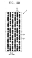
- FIGS. 2A and 2B respectively are schematic drawings of a system region 1 and a data region 2 of an optical disc having regions with physical specifications that are different from each other.
- a gap between rows of pits P1 is greater than a gap between rows of pits P2 in the data region 2.
- the size of a track pitch T1 in the system region 1 is greater than the size of a track pitch T2 in the data region 2.
- the sizes of beam spots S1 and S2 respectively in the system region 1 and the data region 2 must be optimized. If the size of the track pitch T1 in the system region 1 is greater than the size of the track pitch T2 in the data region 2, the size of the beam spot S1 irradiated on the system region 1 is greater than the size of the beam spot S2 irradiated on data region 2.
- the optimum sizes of the beam spots S1 and S1 respectively for the system region 1 and the data region 2 vary according to the sizes or depths of the pits P1 and P2 and the sizes of the track pitches T1 and T2.
- the optimum sizes of the beam spots S1 and S1 also vary according to a method of reading signals from an optical beam reflected by the optical disc.
- the diameters of the beam spots S1 and S2 may respectively be greater than the sizes of the pits P1 and P2.
- the diameters of the beam spots S1 and S2 may respectively be less than twice the sizes of the track pitches T1 and T2.
- an optical beam with a beam spot of the same size is irradiated on all regions of the same optical disc. That is, the reproducing in the data region 2 is performed using the beam spot S1 optimized in the system region 1, or the reproducing in the system region 1 is performed using the beam spot S2 optimized in the data region 2.
- the optimized beam spot S1 in the system region 1 may be inappropriate for the reproduction in data region 2. That is, in the case when the optimized beam spot S1 in the system region 1 is irradiated on the data region2, as depicted in FIG. 2B , the optimized beam spot S1 in the system region 1 irradiates multiple tracks in the data region 2.
- a radio frequency (RF) signal or a servo error signal can be incorrect.
- the optimized beam spot S2 in the data region 2 is irradiated on the system region 1, the reading of the servo error is incorrect as the size of the beam spot S2 optimized in the data region 2 is less than the size of a beam spot required in the system region 1.
- the optimized beam spots S1 and S2 are respectively used in the system region 1 and data region 2, correct reading can be performed in both the system region 1 and the data region 2.
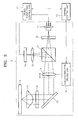
- the optical disc reproducing apparatus includes an optical pick-up 10 that detects signals from an optical disc D, a signal computing control unit 22 that processes signals detected by the optical pick-up 10, and a driving control unit 23 that controls the optical pick-up 10.
- the optical pick-up 10 is controlled such that the optimum sizes of beam spots (for example, beam spots S1 and S2 as described above) can respectively be irradiated on regions of the optical disc D.
- the optical pick-up 10 irradiates a light beam onto the optical disc D and detects an electrical signal from the light beam reflected by the optical disc D.
- the optical pick-up 10 includes an optical path converter 13 to change a path along which the light beam proceeds, a collimating lens 14 that collimates the light beam, an object lens 17 that projects the collimated light beam received from the collimating lens 14 to the optical disc D after focusing the collimated light beam to a predetermined spot size, and an optical detector 19 that converts an optical signal reflected from the optical disc D to an electrical signal.
- the optical pick-up 10 can further include a reflection mirror 15 that bends the optical path of the light beam to optimize the mounting of optical parts. Also, a 1 ⁇ 4 wavelength plate 16 that changes polarization of incident light traveling to the object lens 17 can be included between the reflection mirror 15 and the object lens 17.
- the optical pick-up 10 can further include a grating 12 that diverges light emitted from a light source 11 into 0 order light (main light) and ⁇ order light (sub-light) to detect a tracking error signal using a 3-beam method or a differential push-pull method. A reproducing signal can be obtained from the detected signal of the 0 order light reflected by the optical disc D, and the tracking error signal can be obtained by computing the detected signals of the 0 order light and ⁇ order light.
- the optical pick-up 10 also includes an astigmatic lens 18 to generate an astigmatic aberration so that a focus error signal can be detected by an astigmatic method.
- the collimating lens 14 is installed to be moveable in an optical axis direction to control the spot size of a light beam irradiated onto the optical disc D, and a collimating lens driving unit 21 for driving the collimating lens 14 is included in the optical pick-up 10. As such, the collimating lens 14 moves along a length of the optical beam (i.e., the optical axis direction) between the light source 11 and the object lens 17 to change the size of the optical beam irradiated onto the optical disc D.
- FIG. 3 illustrates the collimating lens 14 as being disposed between the light source 11 and the reflective mirror 15, the collimating lens 14 is not limited thereto.
- the collimating lens 14 may be disposed between the reflective mirror 15 and the object lens 17; or, there may be multiple reflective mirrors 15 configured in the optical pick-up 10, depending upon the shape and structure thereof, so that the collimating lens 14 is disposed between two adjacent reflective mirrors 15 or between the light source 11 and the first of a series of reflective mirrors 15.
- the light source 11 can emit light having a wavelength of 405 nm, which is in a blue-violet wavelength range that meets, for example, HD-DVD specifications.
- the object lens of 17 can have a numerical aperture that meets, for example, the HD-DVD specifications, that is a numerical aperture of approximately 0.65. In this way, when the light source 11 emits light in a blue-violet wavelength range and the object lens 17 has a numerical aperture of 0.65, the optical pick-up 10 can write and/or reproduce information to and/or from a high-density optical disc, particularly, an optical disc with HD-DVD specifications.
- the wavelength of the light source 11 and the numerical aperture of the object lens 17 may vary according to the kind of optical disc D.
- a light source module that emits light with a plurality of wavelengths (for example, a blue wavelength and a red wavelength) can be included as the light source 11, and the object lens 17 can be configured to achieve suitable effective numerical apertures for various cases, or can further include an additional member for controlling the effective numerical apertures.
- the signal computing control unit 22 generates a focus error signal, a tracking error signal, a jitter value, and an RF signal in response to an electrical signal detected at the optical detector 19, and controls a laser diode driver (LDD) (not shown) that drives the light source 11 to control power of the optical beam emitted from the light source 11.
- LDD laser diode driver
- the driving control unit 23 controls a servo of the optical pick-up 10 in response to a signal generated by the signal computing control unit 22.
- the driving control unit 23 controls the collimating lens driving unit 21 so that an optical beam having an optimum size can be irradiated onto the optical disc D.
- the optical disc reproducing apparatus When the optical disc D is loaded in the optical disc reproducing apparatus, the optical disc reproducing apparatus performs a process to recognize the optical disc D. In order to recognize the optical disc D, the optical disc reproducing apparatus moves the optical pick-up 10 to the data region 2 of the optical disc D (S10).
- an optical beam such as a laser diode
- the optical pick-up 10 reads physical parameters or optical parameters of the optical disc D, for example, a reflectance, an RF signal, or a push-pull signal from the optical beam reflected by the optical disc D. Since the reflectance, the RF signal, and the push-pull signal are specific according to specifications of each kind of optical disc D, the kind of optical disc D can be determined using the reflectance, the RF signal, and the push-pull signal (S20). However, the determination of the optical disc D is not limited to the above method.
- the determination of the optical disc D can be achieved through a process of reading disc book type information included in a lead-in area of the optical disc D.
- the optical pick-up 10 determines whether the optical disc D has a system region 1 and a data region 2 having physical specifications that are different from each other or not.
- the optical disc reproducing apparatus performs an optimization matching operation (S23) while performing a focusing servo operation (S21) and/or a tracking servo operation (S22) according to the kind of optical disc D. Then, the optical disc reproducing apparatus moves the optical pick-up 10 to the system region 1 (S30). If the loaded optical disc D is determined as, for example, an HD-DVD in the recognize optical disc process (S20), a process for changing the spot size of an optical beam to be irradiated onto the optical disc D is performed (S31). That is, the driving control unit 23 controls the collimating lens driving unit 21 to move the collimating lens 14, so that the collimating lens 14 can irradiate an optimum spot size of the optical beam onto the system region 1.
- the collimating lens 14 collimates the light beam by converging the light beams radiated from the light source 11. If the collimating lens 14 moves along an optical axis, a distance between the light source 11 that emits radiating light to the collimating lens 14 is changed. As the distance between the light source 11 and the collimating lens 14 changes, the diameter of the collimated light beam changes to thereby change the spot size of the optical beam focused onto the optical disc D through the object lens 17. Accordingly, an optical beam having an optimum spot size can be irradiated onto the system region 1 by moving the collimating lens 14.
- the driving control unit 23 controls the collimating lens driving unit 21 to move the collimating lens 14, so that the collimating lens 14 can irradiate an optimum spot size of optical beam onto the data region 2.
- the collimating lens 14 may be moved to change the diameter of the collimated light beam so as to produce the optimum spot size on the optical disc D.
- an optimized spot size of the optical beam can be irradiated onto each of the regions by controlling the location of the collimating lens 14. Therefore, a stable reproduction of information from the optical disc D can be achieved.
- the spot size of the optical beam is controlled by moving the collimating lens 14.
- the spot size of the optical beam can be changed using various optical methods besides the above-described method.
- the method of reproducing information from an optical disc according to aspects of the present invention and the optical disc reproducing apparatus using the method of reproducing information from the optical disc enable stable reproduction from all regions of the optical disc by minimizing a regional reproduction performance difference caused in the process of reproducing information from the optical disc having a plurality of regions with differing physical specifications.
Landscapes
- Physics & Mathematics (AREA)
- Optics & Photonics (AREA)
- Engineering & Computer Science (AREA)
- Software Systems (AREA)
- Theoretical Computer Science (AREA)
- Optical Recording Or Reproduction (AREA)
- Optical Head (AREA)
Applications Claiming Priority (1)
| Application Number | Priority Date | Filing Date | Title |
|---|---|---|---|
| KR1020070023197A KR100888599B1 (ko) | 2007-03-08 | 2007-03-08 | 광디스크 재생 방법 및 이를 이용한 광디스크 재생 장치 |
Publications (1)
| Publication Number | Publication Date |
|---|---|
| EP1968049A1 true EP1968049A1 (de) | 2008-09-10 |
Family
ID=39223049
Family Applications (1)
| Application Number | Title | Priority Date | Filing Date |
|---|---|---|---|
| EP08100036A Ceased EP1968049A1 (de) | 2007-03-08 | 2008-01-03 | Verfahren zur Wiedergabe von Informationen auf einer optischen Scheibe und Vorrichtung zur Abspielung einer optischen Scheibe unter Anwendung dieses Verfahrens |
Country Status (4)
| Country | Link |
|---|---|
| US (1) | US20080219127A1 (de) |
| EP (1) | EP1968049A1 (de) |
| KR (1) | KR100888599B1 (de) |
| CN (1) | CN101261866A (de) |
Cited By (1)
| Publication number | Priority date | Publication date | Assignee | Title |
|---|---|---|---|---|
| EP2187392A1 (de) * | 2008-11-18 | 2010-05-19 | Thomson Licensing | Appareil permettant d'enregistrer sur un support d'enregistrement optique |
Families Citing this family (1)
| Publication number | Priority date | Publication date | Assignee | Title |
|---|---|---|---|---|
| CN101393753A (zh) * | 2007-09-20 | 2009-03-25 | 新科实业有限公司 | 光学头的制造方法 |
Citations (4)
| Publication number | Priority date | Publication date | Assignee | Title |
|---|---|---|---|---|
| US5701288A (en) | 1994-11-29 | 1997-12-23 | Samsung Electronics Co., Ltd. | Optical pickup device with light spot size adjustment for different density disks |
| WO2005017886A2 (en) | 2003-08-13 | 2005-02-24 | Koninklijke Philips Electronics N.V. | Recordable optical record carrier for multilevel and method for writing thereon |
| EP1675116A2 (de) * | 2004-12-22 | 2006-06-28 | Kabushiki Kaisha Toshiba | Optische Plattenvorrichtung und Steuerverfahren dafür |
| EP1732073A2 (de) | 2005-06-07 | 2006-12-13 | Samsung Electronics Co., Ltd. | Optische Aufzeichnungs-/Wiedergabevorrichtung |
Family Cites Families (7)
| Publication number | Priority date | Publication date | Assignee | Title |
|---|---|---|---|---|
| US3909131A (en) * | 1974-02-12 | 1975-09-30 | United Technologies Corp | Surface gauging by remote image tracking |
| JP3770921B2 (ja) * | 1993-03-31 | 2006-04-26 | 三菱電機株式会社 | 光ディスク装置 |
| JPH0773506A (ja) * | 1993-08-31 | 1995-03-17 | Victor Co Of Japan Ltd | 光記録媒体及びその再生装置 |
| JPH07244919A (ja) * | 1994-03-08 | 1995-09-19 | Ricoh Co Ltd | 情報記憶装置 |
| US6449235B1 (en) * | 1998-04-04 | 2002-09-10 | Lg Electronics, Inc. | Optical pick-up apparatus and optical recording/reproducing apparatus using the same |
| US7443778B2 (en) * | 2003-02-27 | 2008-10-28 | Matsushita Electric Industrial Co., Ltd. | Optical head device and optical information device using the same, computer, optical disk player, car navigation system, optical disk recorder, and optical disk server |
| US7210632B2 (en) * | 2003-06-02 | 2007-05-01 | Symbol Technologies, Inc. | On-axis control over scanning beam spot size and shape in electro-optical readers |
-
2007
- 2007-03-08 KR KR1020070023197A patent/KR100888599B1/ko not_active Expired - Fee Related
- 2007-09-11 US US11/853,242 patent/US20080219127A1/en not_active Abandoned
-
2008
- 2008-01-03 EP EP08100036A patent/EP1968049A1/de not_active Ceased
- 2008-01-11 CN CNA2008100951800A patent/CN101261866A/zh active Pending
Patent Citations (4)
| Publication number | Priority date | Publication date | Assignee | Title |
|---|---|---|---|---|
| US5701288A (en) | 1994-11-29 | 1997-12-23 | Samsung Electronics Co., Ltd. | Optical pickup device with light spot size adjustment for different density disks |
| WO2005017886A2 (en) | 2003-08-13 | 2005-02-24 | Koninklijke Philips Electronics N.V. | Recordable optical record carrier for multilevel and method for writing thereon |
| EP1675116A2 (de) * | 2004-12-22 | 2006-06-28 | Kabushiki Kaisha Toshiba | Optische Plattenvorrichtung und Steuerverfahren dafür |
| EP1732073A2 (de) | 2005-06-07 | 2006-12-13 | Samsung Electronics Co., Ltd. | Optische Aufzeichnungs-/Wiedergabevorrichtung |
Cited By (1)
| Publication number | Priority date | Publication date | Assignee | Title |
|---|---|---|---|---|
| EP2187392A1 (de) * | 2008-11-18 | 2010-05-19 | Thomson Licensing | Appareil permettant d'enregistrer sur un support d'enregistrement optique |
Also Published As
| Publication number | Publication date |
|---|---|
| CN101261866A (zh) | 2008-09-10 |
| KR100888599B1 (ko) | 2009-03-12 |
| US20080219127A1 (en) | 2008-09-11 |
| KR20080082387A (ko) | 2008-09-11 |
Similar Documents
| Publication | Publication Date | Title |
|---|---|---|
| US7778136B2 (en) | Optical recording medium driving apparatus and focusing method | |
| US20050047292A1 (en) | Optical pickup and optical recording and/or reproducing apparatus adopting the same | |
| US7307927B2 (en) | Optical disk apparatus and method for recording and reproducing an optical disk | |
| JP2006309809A (ja) | 光ディスク装置及び光ディスク判別方法 | |
| US6556302B2 (en) | Apparatus for and method of determining information record medium | |
| KR20100076784A (ko) | 비구면 렌즈 및 이를 대물렌즈로 채용한 광픽업 | |
| US7920449B2 (en) | Method of controlling focus of optical information storage media recording and/or reproduction apparatus and apparatus therefor | |
| KR20040076648A (ko) | 호환형 광픽업 | |
| US20080219127A1 (en) | Method of reproducing information from optical disc and optical disc reproducing apparatus using the same | |
| US20070274174A1 (en) | Optical disk device and optical disk gain adjusting method | |
| EP1998330B1 (de) | Verfahren zur Unterscheidung zwischen optischen Scheiben von verschiedenen Arten und Gerät für optische Scheiben | |
| KR20060046848A (ko) | 광 디스크 유형 판별 방법 및 그 데이터 기록 및/또는재생 장치 | |
| US7978589B1 (en) | System and method for verifying write performance during optical recording | |
| US7729221B2 (en) | Optical disk discrimination method and optical disk device | |
| US7349299B2 (en) | Method of optical disc discrimination | |
| US7889606B2 (en) | Optical disc drive and control method thereof | |
| US7649826B2 (en) | Optical information recording reproduction device | |
| US20080089193A1 (en) | Apparatus and method for controlling focus jump between recording layers in high-density multi-layer disk | |
| US7518967B2 (en) | Position control method and device, and optical disk device | |
| JP5169582B2 (ja) | 光ピックアップ及びこれを用いた光ディスク装置 | |
| JP2009123253A (ja) | 光ピックアップ | |
| US20060140104A1 (en) | Optical pickup and optical disk apparatus | |
| EP2667381B1 (de) | Optisches Plattengerät | |
| US7940618B2 (en) | Method for identifying optical disc type, data recording and/or reproducing apparatus, and medium using the same | |
| US20080094953A1 (en) | Focus pull-in method and optical disc drive thereof |
Legal Events
| Date | Code | Title | Description |
|---|---|---|---|
| PUAI | Public reference made under article 153(3) epc to a published international application that has entered the european phase |
Free format text: ORIGINAL CODE: 0009012 |
|
| AK | Designated contracting states |
Kind code of ref document: A1 Designated state(s): AT BE BG CH CY CZ DE DK EE ES FI FR GB GR HR HU IE IS IT LI LT LU LV MC MT NL NO PL PT RO SE SI SK TR |
|
| AX | Request for extension of the european patent |
Extension state: AL BA MK RS |
|
| 17P | Request for examination filed |
Effective date: 20081212 |
|
| 17Q | First examination report despatched |
Effective date: 20090128 |
|
| AKX | Designation fees paid |
Designated state(s): DE GB NL |
|
| STAA | Information on the status of an ep patent application or granted ep patent |
Free format text: STATUS: THE APPLICATION HAS BEEN REFUSED |
|
| 18R | Application refused |
Effective date: 20091105 |