EP1968157B1 - Antenne triaxiale - Google Patents
Antenne triaxiale Download PDFInfo
- Publication number
- EP1968157B1 EP1968157B1 EP08010602A EP08010602A EP1968157B1 EP 1968157 B1 EP1968157 B1 EP 1968157B1 EP 08010602 A EP08010602 A EP 08010602A EP 08010602 A EP08010602 A EP 08010602A EP 1968157 B1 EP1968157 B1 EP 1968157B1
- Authority
- EP
- European Patent Office
- Prior art keywords
- axis
- arms
- aforementioned
- winding wire
- head
- Prior art date
- Legal status (The legal status is an assumption and is not a legal conclusion. Google has not performed a legal analysis and makes no representation as to the accuracy of the status listed.)
- Expired - Lifetime
Links
Images






Classifications
-
- H—ELECTRICITY
- H01—ELECTRIC ELEMENTS
- H01Q—ANTENNAS, i.e. RADIO AERIALS
- H01Q7/00—Loop antennas with a substantially uniform current distribution around the loop and having a directional radiation pattern in a plane perpendicular to the plane of the loop
- H01Q7/06—Loop antennas with a substantially uniform current distribution around the loop and having a directional radiation pattern in a plane perpendicular to the plane of the loop with core of ferromagnetic material
-
- H—ELECTRICITY
- H01—ELECTRIC ELEMENTS
- H01Q—ANTENNAS, i.e. RADIO AERIALS
- H01Q1/00—Details of, or arrangements associated with, antennas
- H01Q1/27—Adaptation for use in or on movable bodies
- H01Q1/32—Adaptation for use in or on road or rail vehicles
- H01Q1/3208—Adaptation for use in or on road or rail vehicles characterised by the application wherein the antenna is used
- H01Q1/3233—Adaptation for use in or on road or rail vehicles characterised by the application wherein the antenna is used particular used as part of a sensor or in a security system, e.g. for automotive radar, navigation systems
-
- H—ELECTRICITY
- H01—ELECTRIC ELEMENTS
- H01Q—ANTENNAS, i.e. RADIO AERIALS
- H01Q21/00—Antenna arrays or systems
- H01Q21/24—Combinations of antenna units polarised in different directions for transmitting or receiving circularly and elliptically polarised waves or waves linearly polarised in any direction
-
- H—ELECTRICITY
- H01—ELECTRIC ELEMENTS
- H01Q—ANTENNAS, i.e. RADIO AERIALS
- H01Q7/00—Loop antennas with a substantially uniform current distribution around the loop and having a directional radiation pattern in a plane perpendicular to the plane of the loop
- H01Q7/06—Loop antennas with a substantially uniform current distribution around the loop and having a directional radiation pattern in a plane perpendicular to the plane of the loop with core of ferromagnetic material
- H01Q7/08—Ferrite rod or like elongated core
-
- H—ELECTRICITY
- H01—ELECTRIC ELEMENTS
- H01F—MAGNETS; INDUCTANCES; TRANSFORMERS; SELECTION OF MATERIALS FOR THEIR MAGNETIC PROPERTIES
- H01F3/00—Cores, Yokes, or armatures
- H01F2003/005—Magnetic cores for receiving several windings with perpendicular axes, e.g. for antennae or inductive power transfer
-
- H—ELECTRICITY
- H01—ELECTRIC ELEMENTS
- H01F—MAGNETS; INDUCTANCES; TRANSFORMERS; SELECTION OF MATERIALS FOR THEIR MAGNETIC PROPERTIES
- H01F3/00—Cores, Yokes, or armatures
Definitions
- the present invention concerns a three-axis antenna for wireless operation of locking and unlocking automobile doors, for example.
- Three axial windings are completed about one core in conventional three-axis antennas.
- a three-axis antenna that combines a two-axis antenna with a one-axis antenna is disclosed in the gazette of Japanese Kokai Publication 2003-92509 .
- the thickness is increased in aforementioned structure because the winding in one axis overlaps the winding in the other axis in a two-axis antenna, which makes it unsuited for miniaturization in terms of height.
- Patent literature 1 Gazette of Japanese Kokai Publication 2003-92509
- EP 1 489 683 A1 which is a family member of WO 03/075403 A , discloses that the size of an antenna coil is reduced and it is possible to prevent lowering of the reception sensitivity due to difference of the arrangement position of the antenna coil.
- a first coil and a second coil are wound in such a manner that their winding axes orthogonally intersect each other, and a third coil is wound around an outer circumference of the first coil and the second coil, so that a winding axis is provided to be orthogonal to the winding axes of the first coil and the second coil.
- GB 2 326 769 A which is a family member of DE 19718423 A1 , discloses an antenna that consists of three coiled elements with mutually perpendicular axes, having either air or ferrite cores, and this antenna is connected to a receiver.
- the antenna and receiver system is preferably contained in a credit-card size housing or a key-fob housing where is may feature in a remote control vehicle anti-theft system.
- the three coils ensure reliable reception of an inductive signal from a single coil transmitter in the vehicle.
- EP 1 376 762 A1 discloses a three-axis antenna chip that includes a cross-shaped core e.g. made of a magnetic substance.
- the core includes an X-axis core piece and a Y-axis core piece.
- the core pieces are laid on top of each other such that the core pieces extend perpendicular to each other.
- An X-axis coil portion is provided about the X-axis core piece, and a Y-axis coil portion is provided about the Y-axis core piece.
- a Z-axis coil portion is provided about a Z-axis that is perpendicular to the X-axis core piece and the Y-axis core piece.
- the three-axis antenna chip has small size.
- the issue to be resolved is the attainment of sensitivity without deviating in any of XYZ directions in an orthogonal coordinate system with windings about a cross-shaped core.
- a three-axis antenna according to the invention is set out in Claim 1.
- the head section of the X-axis arm and the head section of the Y-axis arm are retained when the cross-shaped core is set in a case with a bottom, and a retaining tab that determines the position in the Z-axis direction of the X-axis arm and the Y-axis arm is provided. Consequently, the cross-shaped core, X-axis arm and Y-axis arm can be easily oriented in the vertical direction, and coupling of each arm can be avoided, thereby attaining sensitivity without deviation concerning any of the XYZ axis winding wires.
- Figure 1 presents the antenna coil unit pursuant to Embodiment 1 of the present invention.
- Case 1 as shown in Figure 2 , a perspective diagram, is a roughly square case with a bottom having a pair of notches cut in the side walls. It may be constructed of resin, for example.
- Convex members 12 with a one-quarter fan shape are formed in the bottom of case 1 at the four corners to divide the bottom into roughly nine equal portions.
- Grooves 11 are formed among these convex members 12 so as to match the cross shape of cross-shaped core 2 in order to house aforementioned cross-shaped core 2 shown in Figure 5 with the completed winding.
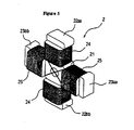
- Cross-shaped core 2 has a prismatic-shaped base section 21 in the center, as shown in Figure 4 .
- X-axis arms 22a, 22b and Y-axis arms 23a, 23b extend outward in four directions at 90-degree angles from base section 21.
- projection 13 that is formed in the center of the bottom of case 1, as shown in Figure 2 , is inserted into a hole formed in base section 21 of aforementioned cross-shaped core 2.
- This structure permits orientation of cross-shaped core 2.
- Individual head sections 22aa, 22bb, 23aa, 23bb of X-axis arms 22a, 22b, Y-axis arms 23a, 23b of cross-shaped core 2 are expanded. Magnetic flux is generated and the antenna sensitivity is enhanced since the area of the head section is expanded by so doing.
- Retaining tab 4 that retains each head section 22aa, 22bb, 23aa, 23bb is shown in Figure 3 .
- Retaining tab 4 has retaining sections 42, 42 rising from both edges of long seat section 41, and projection tabs 43, 43 that are formed at the upper section of each of the retaining sections 42, 42 so as to protrude outward laterally with the function of preventing downward movement when set in the holes formed at the bottom of case 1.
- the edges of the coil are caught in projection tabs 43, 43, and the edges of the coil are connected by soldering to the terminals that extend from external terminals 31-38 to projection tabs 43, 43.
- the surface at retaining tab 4 in contact with each of head sections 22aa, 22bb, 23aa, 23bb is formed so as to be flat.
- Aforementioned retaining tab 4 is disposed in the concave section formed in convex member 12 that is formed at the bottom of case 1.
- Cross-shaped core 2 is housed as shown in Figure 2 . Head sections 22aa, 22bb, 23aa, 23bb are retained by the corresponding retaining tab 4.
- head sections 22aa, 22bb of X-axis arms 22a, 22b and head sections 23aa, 23bb of Y-axis arms 23a, 23b are respectively retained, and the orientation of cross-shaped core 2, X-axis arms 22a, 22b, and of Y-axis arms 23a, 23b in the height direction can be easily set appropriately since retaining tab 4 determines the Z-axis directional position of X-axis arms 22a, 22b and of Y-axis arms 23a, 23b (position in direction of height).
- Z-axis winding wire is provided in a condition so as to uniformly cover the head surfaces of X-axis arms 22a, 22b and the head surfaces of Y-axis arms 23a, 23b in cross-shaped core 2 (Z-axis winding wire uniformly provided in the portions corresponding to the head sections and in the vertical direction).
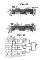
- the magnetic flux number passing through each of the head sections 22aa, 22bb, 23aa, 23bb and part of the corresponding Z-axis winding wire (portion corresponding to aforementioned head section) is roughly the same figure at head section 22aa and at head section 22bb, as shown in Figure 10 (a) .
- Z-axis winding wire in a structure in which Z-axis winding wire is provided in a condition so as to not uniformly cover the head surfaces of X-axis arms 22a, 22b and the head surfaces of Y-axis arms 23a, 23b in cross-shaped core 2 (Z-axis winding wire not uniformly provided in the portions corresponding to the head sections and in the vertical direction) or in a structure that does not determine the Z-axis directional position (position in direction of height), Z-axis winding wire develops deviation at the head surface of X-axis arms 22a, 22b or at the head surface of Y-axis arms 23a, 23b in cross-shaped core 2, as shown in Figure 10 (b) .
- a state is presented in which the magnetic flux number passing through each head surface differs, resulting in the development of a potential difference at the portion of the Z-axis winding wire facing aforementioned head surface.
- X-axis winding wire 24 is wound about X-axis arms 22a, 22b and Y-axis winding wire 25 is wound about Y-axis arms 23a, 23b in cross-shaped core 2, as shown in Figure 5 .
- the winding method of X-axis winding wire 24 and of Y-axis winding wire 25 is explained here.
- S shown in Figure 6 (a) represents the winding origin, with X-axis winding wire 24 proceeding in the direction represented by the arrows.
- the winding range of X-axis winding wire 24 begins from the root section of X-axis arm 22a and proceeds toward head section 22aa of X-axis arm 22a, which is one arm (direction of arrow D1).
- winding When winding reaches the boundary section with head section 22aa, as shown by the arrows denoting the winding in Figure 6 (b) , it proceeds from head section 22aa to the intermediate point of X-axis arm 22a with the root section and then straddles base section 21, after which it continues to the side of head section 22bb of X-axis arm 22b without winding about head section 22bb via the intermediate point with the root section of X-axis arm 22b which is the other arm, after which winding of X-axis winding wire 24 resumes from the boundary section of head section 22bb, which is the spanning destination.
- the winding range of X-axis winding wire 24 begins from the boundary section with head section 22bb of X-axis arm 22b and then proceeds toward the root section of X-axis arm 22b (direction of arrow D2).
- the end of X-axis winding wire 24 is caught by projection tab 43 of retaining tab 4 corresponding to head sections 22aa, 22bb, respectively.
- the edge of this coil is connected by soldering to the terminals that extend from external terminals 31-38 to the vicinity of projection tab 43.
- the end of Y-axis winding wire 25 is caught by projection tab 43 of retaining tab 4 corresponding to head sections 23aa, 23bb, respectively.
- the edge of this coil is connected by soldering to the terminals that extend from external terminals 31-38 to the vicinity of projection tab 43.
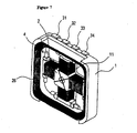
- Z-axis winding wire 26 is wound about an empty core in a virtually square shape, as shown in Figure 7 . It is disposed in a ring-shaped passage formed along the inner wall of case to which it is fixed. Of course, the winding shape of Z-axis winding wire 26 is not restricted to square shape. Other suitable shapes are permitted, such as round or oval.
- Cross-shaped core 2 about which is wound X-axis winding wire 24 and Y-axis winding wire 25 is disposed as shown in Figure 7 .
- Z-axis winding wire 26 is installed in a virtually square shape so as to enclose the outside of head sections 22aa, 22bb of X-axis arms 22a, 22b and the outside of head sections 23aa, 23bb of Y-axis arms 23a, 23b ( Figure 1 , Figure 7 ).
- Z-axis winding wire is installed in a condition so as to cover the entire head surfaces of X-axis arms 22a, 22b and the head surfaces of Y-axis arms 23a, 23b in cross-shaped core 2.
- edges of external terminals 35, 36 that are installed on the outside of case I protrude near the position where Z-axis winding wire 26 is disposed in case 1, and each end of Z-axis winding wire 26 is connected.
- a completed diagram of the three-axis antenna presents the structure in the planar figure that is Figure 8 .
- a cross-sectional view along A-A of Figure 8 is shown in Figure 9 .
- the potentials of windings 24, 25 are equal on the sides of head sections 22aa, 22bb of a pair of X-axis arms 22a, 22b and on the sides of head sections 23aa, 23bb of a pair of Y-axis arms 23a, 23b since X-axis winding wire 24 and Y-axis winding wire 25 are wound as explained using Figure 6 .
- Figure 11 shows the structure of the receiving device using antenna coil unit 100 fitted with the three-axis antenna having aforementioned structure. It is provided with first amplifier 81 connected to external terminal 31 that is connected to the winding origin edge XS of X-axis winding wire 24 and to external terminal 32 that is connected to the winding terminus edge XF, second amplifier 82 connected to external terminal 33 that is connected to the winding origin edge YS of Y-axis winding wire 25 and to external terminal 34 that is connected to the winding terminus edge YF, and third amplifier 83 connected to external terminal 35 that is connected to the winding origin edge ZS of Z-axis winding wire 26 and to external terminal 36 that is connected to the winding terminus edge ZF.
- first amplifier 81 connected to external terminal 31 that is connected to the winding origin edge XS of X-axis winding wire 24 and to external terminal 32 that is connected to the winding terminus edge XF
- second amplifier 82 connected to external terminal 33 that is connected to the winding origin edge YS
- First amplifier 81 is provided with capacitor C1 that is connected between two input terminals
- second amplifier 82 is provided with capacitor C2 that is connected between two input terminals
- third amplifier 83 is provided with capacitor C3 that is connected between two input terminals.
- Reception selection circuit 84 that is provided treats the output from aforementioned first to third amplifiers 81 to 83 as received signals. In short, reception selection circuit 84 compares the output levels of amplifiers 81 to 83, selects the signal having the greater output level and outputs it to the processing circuit of the received signal.
- Terminals 37 and 38 that are connected to the center taps XC, YC of X-axis winding wire 24 and Y-axis winding wire 25 as well as terminal 35 that is connected to winding origin edge ZS of Z-axis winding wire 26 are grounded by common connection to the circuit board side.
- the suffixes of these connections XC, YC, ZS are represented by CCS.
- CCS the grounding of center taps XC, YC with the terminal connected to winding terminus ZF of Z-axis winding wire 26 would be represented as CCF.
- connection of either edge XS, XF with either edge YS, YF and with either edge ZS, ZF without using center taps XC, YC with X-axis winding wire 24 and Y-axis winding wire 25 would be the connections represented by SSS, FFF, FFS, FSF, FSS, SFF, SFS, SSF.
- Comparative trials of these eight types of received sensitivity characteristics with the received sensitivity characteristics of aforementioned CCS show that the CSS connection provides the highest peak value and that the characteristics are arranged according to the peak frequency in the XYZ axes. In short, this indicates that characteristics having no deviation in three axes are obtained.
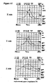
- Figure 14 shows the case of a CCS connection while Figure 15 shows the case of an FFF connection.
- the trial.results in Figure 15 indicate deviation of the central frequency due to coupling in the case of an FFF connection.
- the ordinate in each chart represents the impedance, with one calibration representing 50 K ⁇ .
- the abscissa is the frequency.
- the center of the abscissa is 134.2 KHz and the amplitude of the abscissa is 30 KHz.
- Tests on the characteristics of CCF revealed characteristics virtually identical with those of CCS.
- the structure shown in Figure 11 is provided with eight terminals 31 to 38 in the three-axis antenna, but a structure in which a three-axis antenna is provided with six terminals in which terminals 37, 38 and terminal 35 have shared connections, as shown in Figure 12 , may be adopted.
- X-axis winding wire 24 may be structured from two winding wires
- Y-axis winding wire 25 may also be structured from two winding wires.
- a structure may be adopted in which the terminals 37A, 37B, 38A, 38B connected to the individual center taps XC, YC of X-axis winding wire 24 and Y-axis winding wire 25 are commonly connected with terminal 35 on the circuit board side for grounding.
- An antenna coil unit provided with six external terminals can be implemented by incorporating capacitors C1 to C3 in case 1.
- an antenna coil unit that incorporates amplifiers 81 to 83 in case 1 can also be implemented.
- six terminals can be completed by collecting in one terminal each terminus of each winding wire connected to the ground.
- Retaining tab 4 in Figure 3 may have a structure that is integrated with cross-shaped core 2 so as to cover head sections 22aa, 22bb, 23aa, 23bb of cross-shaped core 2.
- Fan shaped convex member 12 in case 1 shown in Figure 2 is not restricted to this shape. Rectangular or round shapes are also permitted.
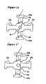
- Winding as shown in Figure 16 and Figure 17 may be adopted instead of the winding method of X-axis winding wire 24 shown in Figure 6 .
- the winding origin may be from head section 22aa of cross-shaped core 2, proceeding toward the root section of X-axis arm 22a, after which it diagonally straddles base section 21 and reaches the root section of X-axis arm 22b, the other arm, from which point the winding would proceed from the root section of aforementioned X-axis arm 22b toward the side of head section 22bb so that the magnetic flux directions due to winding wires that are wound about X-axis arms 22a, 22b would be consistent.
- the winding origin may be from head section 22aa of cross-shaped core 2, proceeding toward the root section of X-axis arm 22a, after which it straddles base section 21 directly to the opposite side to reach the root section of X-axis arm 22b, the other arm, from which point the winding would proceed from the root section of aforementioned X-axis arm 22b toward the side of head section 22bb so that the magnetic flux due to winding wires that are wound about X-axis arms 22a and 22b would offset each other.
- any number of layers may be wound in bank winding from head section 22aa to the root section of X-axis arm 22a.
- the winding technique of winding wire from the root section of X-axis arm 22b to head section 22bb may be identical.
Landscapes
- Engineering & Computer Science (AREA)
- Computer Security & Cryptography (AREA)
- Radar, Positioning & Navigation (AREA)
- Remote Sensing (AREA)
- Variable-Direction Aerials And Aerial Arrays (AREA)
- Coils Or Transformers For Communication (AREA)
- Details Of Aerials (AREA)
Claims (3)
- Antenne à trois axes comprenant un noyau en forme de croix (2) et un boîtier (1), dans laquelle le noyau en forme de croix (2) comprend une paire de bras (22a, 22b) suivant l'axe des X se projetant dans la direction de l'axe des X et une paire de bras (23a, 23b) suivant l'axe des Y se projetant dans la direction de l'axe des Y orthogonale à la direction de l'axe des X mentionnée ci-dessus dans un système orthogonal de coordonnées XYZ,
un fil d'enroulement (24) suivant l'axe des X enroulé autour des bras (22a, 22b) suivant l'axe des X mentionnés ci-dessus,
un fil d'enroulement (25) suivant l'axe des Y enroulé autour des bras (23a, 23b) suivant l'axe des Y mentionnés ci-dessus, et
un fil d'enroulement (26) suivant l'axe des Z prévu dans un état renfermant le noyau (2) en forme de croix mentionné ci-dessus à l'extérieur de tronçons de tête (22aa, 22bb) des bras (22a, 22b) suivant l'axe des X mentionnés ci-dessus et de tronçons de tête (23aa, 23bb) des bras (23a, 23b) suivant l'axe des Y mentionnés ci-dessus ; et
le noyau en forme de croix (2) mentionné ci-dessus et le fil d'enroulement (26) suivant l'axe des Z sont reçus dans le boîtier (1), les tronçons de tête (22aa, 22bb) des bras (22a, 22b) suivant l'axe des X et les tronçons de tête (23aa, 23bb) des bras (23a, 23b) suivant l'axe des Y sont respectivement retenus ;
ladite antenne caractérisée par ;
les positions directionnelles suivant l'axe des Z des bras (22a, 22b) suivant l'axe des X et des bras (23a, 23b) suivant l'axe des Y reçus dans ledit boîtier sont déterminées par des languettes de retenue placées entre chaque tronçon de tête (22aa, 22bb) des bras (22a, 22b) suivant l'axe des X mentionnés ci-dessus et le boîtier (1) mentionné ci-dessus, et entre chaque tronçon de tête (23aa, 23bb) des bras (23a, 23b) suivant l'axe des Y mentionnés ci-dessus et le boîtier (1) mentionné ci-dessus de sorte que le fil d'enroulement suivant l'axe des Z soit prévu dans un état tel qu'il couvre de manière uniforme des surfaces de tête des bras (22a, 22b) suivant l'axe des X et des bras (23a, 23b) suivant l'axe des Y ;
où chaque languette de retenue comprend des tronçons de retenue (42) s'élevant des deux bords d'un tronçon d'assise long (41) et des languettes de projection (43) qui sont formées au niveau du tronçon supérieur de chacun des tronçons de retenue (42) de manière à faire saillie vers l'extérieur de manière latérale afin d'empêcher un mouvement descendant lorsqu'elles sont fixées dans des trous formés au fond du boîtier (1) ; et
un trou est formé au niveau du tronçon de racine (21) des bras (22a, 22b, 23a, 23b) et une première protubérance (13) est formée dans le centre du boîtier (1) pour s'engager avec le trou mentionné ci-dessus au niveau du tronçon de racine (21) mentionné ci-dessus des bras (22a, 22b, 23a, 23b). - Antenne à trois axes de la revendication 1 dans laquelle le tronçon de racine (21) de chaque tronçon de tête (22aa, 22bb, 23aa, 23bb) des bras (22a, 22b) suivant l'axe des X et des bras (23a, 23b) suivant l'axe des Y est plus grand que celui de l'autre partie du noyau en forme de croix (2).
- Antenne à trois axes de la revendication 1 comprenant en outre des bornes externes (31-38), où les bords de la bobine sont connectés par soudure à des bornes qui s'étendent des bornes externes (31-38) jusqu'à des deuxièmes protubérances (43).
Applications Claiming Priority (2)
| Application Number | Priority Date | Filing Date | Title |
|---|---|---|---|
| JP2004071481 | 2004-03-12 | ||
| EP05720489A EP1727236B1 (fr) | 2004-03-12 | 2005-03-10 | Antenne trois axes et dispositif de réception |
Related Parent Applications (2)
| Application Number | Title | Priority Date | Filing Date |
|---|---|---|---|
| EP05720489A Division EP1727236B1 (fr) | 2004-03-12 | 2005-03-10 | Antenne trois axes et dispositif de réception |
| EP05720489.3 Division | 2005-03-10 |
Publications (2)
| Publication Number | Publication Date |
|---|---|
| EP1968157A1 EP1968157A1 (fr) | 2008-09-10 |
| EP1968157B1 true EP1968157B1 (fr) | 2011-05-11 |
Family
ID=34975898
Family Applications (2)
| Application Number | Title | Priority Date | Filing Date |
|---|---|---|---|
| EP08010602A Expired - Lifetime EP1968157B1 (fr) | 2004-03-12 | 2005-03-10 | Antenne triaxiale |
| EP05720489A Expired - Lifetime EP1727236B1 (fr) | 2004-03-12 | 2005-03-10 | Antenne trois axes et dispositif de réception |
Family Applications After (1)
| Application Number | Title | Priority Date | Filing Date |
|---|---|---|---|
| EP05720489A Expired - Lifetime EP1727236B1 (fr) | 2004-03-12 | 2005-03-10 | Antenne trois axes et dispositif de réception |
Country Status (7)
| Country | Link |
|---|---|
| US (2) | US7616166B2 (fr) |
| EP (2) | EP1968157B1 (fr) |
| JP (2) | JP4426574B2 (fr) |
| KR (1) | KR100881118B1 (fr) |
| CN (3) | CN1930733B (fr) |
| DE (1) | DE602005022838D1 (fr) |
| WO (1) | WO2005088767A1 (fr) |
Families Citing this family (42)
| Publication number | Priority date | Publication date | Assignee | Title |
|---|---|---|---|---|
| RU2321926C2 (ru) * | 2003-10-16 | 2008-04-10 | Сумида Корпорейшн | Антенная катушка и антенное устройство |
| KR101065345B1 (ko) | 2006-04-07 | 2011-09-20 | 스미다 코포레이션 가부시키가이샤 | 안테나 코일 |
| KR101095883B1 (ko) * | 2006-04-10 | 2011-12-21 | 스미다 코포레이션 가부시키가이샤 | 코일 부품 |
| JP3957000B1 (ja) * | 2006-07-07 | 2007-08-08 | 株式会社村田製作所 | 基板実装用アンテナコイル及びアンテナ装置 |
| EP1887587A1 (fr) * | 2006-08-12 | 2008-02-13 | Kaschke KG GmbH & Co. | Ensemble de bobines |
| JP4724623B2 (ja) * | 2006-08-29 | 2011-07-13 | スミダコーポレーション株式会社 | アンテナコイル |
| EP2026406A1 (fr) * | 2007-08-14 | 2009-02-18 | Oticon A/S | Unité d'antenne multifonction |
| GB0724703D0 (en) * | 2007-12-19 | 2008-01-30 | Rhodes Mark | Co-located transmit-receive antenna system |
| JP2009267767A (ja) * | 2008-04-25 | 2009-11-12 | Hitachi Ferrite Electronics Ltd | 低周波用3軸受信アンテナ装置 |
| JP2009296107A (ja) | 2008-06-03 | 2009-12-17 | Sumida Corporation | 受信アンテナコイル |
| WO2010036980A1 (fr) * | 2008-09-27 | 2010-04-01 | Witricity Corporation | Systèmes de transfert d'énergie sans fil |
| KR20110117119A (ko) | 2009-01-30 | 2011-10-26 | 도다 고교 가부시끼가이샤 | 자성체 안테나, rf 태그 및 상기 rf 태그를 실장한 기판 |
| JP4905506B2 (ja) * | 2009-06-22 | 2012-03-28 | 株式会社村田製作所 | アンテナ装置 |
| JP2011135560A (ja) * | 2009-11-27 | 2011-07-07 | Toko Inc | アンテナコイルとその製造方法 |
| JP5161901B2 (ja) * | 2010-02-15 | 2013-03-13 | スミダコーポレーション株式会社 | アンテナコイル |
| CN102834973B (zh) * | 2010-04-13 | 2015-01-21 | 日立金属株式会社 | 三轴天线及用于该三轴天线的芯组装体 |
| JP5403279B2 (ja) * | 2010-08-04 | 2014-01-29 | 戸田工業株式会社 | Rfタグの製造方法、磁性体アンテナの製造方法及び当該rfタグを実装した基板、通信システム |
| WO2012053089A1 (fr) * | 2010-10-21 | 2012-04-26 | 東京特殊電線株式会社 | Composant de bobine et unité de composant de bobine |
| US8704721B2 (en) | 2011-08-08 | 2014-04-22 | Rf Technologies, Inc. | Multi-axial resonant ferrite core antenna |
| JP5093412B2 (ja) * | 2012-01-12 | 2012-12-12 | 株式会社村田製作所 | アンテナコイル及びアンテナ装置 |
| RU2524838C2 (ru) * | 2012-08-27 | 2014-08-10 | Федеральное государственное унитарное предприятие "Ростовский-на-Дону научно-исследовательский институт радиосвязи" (ФГУП "РНИИРС") | Трехосное опорно - поворотное устройство |
| JP2014107691A (ja) * | 2012-11-27 | 2014-06-09 | Tokai Rika Co Ltd | アンテナ装置 |
| JP2014107692A (ja) * | 2012-11-27 | 2014-06-09 | Tokai Rika Co Ltd | アンテナ装置 |
| US10164337B2 (en) * | 2013-03-15 | 2018-12-25 | Ricoh Company, Ltd. | Antenna device |
| JP5913268B2 (ja) * | 2013-11-29 | 2016-04-27 | 東光株式会社 | 3軸アンテナ |
| JP6179543B2 (ja) * | 2014-05-13 | 2017-08-16 | 株式会社村田製作所 | 3軸アンテナ |
| KR101873855B1 (ko) * | 2015-02-23 | 2018-07-03 | 한국전자통신연구원 | 3축 코일 센서 및 그것을 포함하는 자기장 측정 장치 |
| ES2716882T3 (es) * | 2015-11-04 | 2019-06-17 | Premo Sa | Dispositivo de antena para operaciones de HF y LF |
| KR101638310B1 (ko) | 2016-01-20 | 2016-07-12 | (주)에프원테크놀로지 | 3축 코일 안테나 및 그 제조방법 |
| KR101638311B1 (ko) | 2016-02-29 | 2016-07-12 | (주)에프원테크놀로지 | 3축 코일 안테나의 단자부 및 이의 제조방법 |
| WO2017183933A1 (fr) * | 2016-04-21 | 2017-10-26 | 주식회사 아모그린텍 | Module d'antenne à trois axes et système d'entrée sans clé le comprenant |
| KR102021337B1 (ko) * | 2016-04-21 | 2019-09-16 | 주식회사 아모그린텍 | 저주파 안테나 모듈 및 이를 포함하는 키리스 엔트리 시스템 |
| WO2017183934A1 (fr) * | 2016-04-21 | 2017-10-26 | 주식회사 아모그린텍 | Module d'antenne à trois axes et système d'entrée sans clé comprenant celui-ci |
| WO2017183935A1 (fr) * | 2016-04-21 | 2017-10-26 | 주식회사 아모그린텍 | Module d'antenne basse fréquence à trois axes et système d'entrée sans clé comprenant le module d'antenne |
| KR102020799B1 (ko) * | 2016-04-21 | 2019-09-11 | 주식회사 아모그린텍 | 저주파 안테나 모듈 및 이를 포함하는 키리스 엔트리 시스템 |
| KR101927836B1 (ko) * | 2016-10-04 | 2018-12-13 | 주식회사 아모그린텍 | 3축 안테나 모듈 및 이를 포함하는 키리스 엔트리 시스템 |
| WO2018083249A1 (fr) * | 2016-11-04 | 2018-05-11 | Premo, Sl | Unité de puissance magnétique compacte pour un système électronique de puissance |
| CN106602251B (zh) * | 2016-12-16 | 2019-06-21 | 无锡科锐漫电子科技有限公司 | 低频接收天线及其制造方法 |
| CN106952710B (zh) * | 2017-05-12 | 2018-10-30 | 福州大学 | 一种用于多负载的无线充电磁耦合结构及其电路 |
| EP3404768B1 (fr) * | 2017-05-18 | 2019-12-04 | Premo, S.A. | Antenne triaxiale à profil bas |
| DE112018004281T5 (de) * | 2017-09-28 | 2020-05-07 | Murata Manufacturing Co., Ltd. | Antennenvorrichtung und die antennenvorrichtung umfassende mehrachsige antennenvorrichtung |
| EP3855566B1 (fr) * | 2020-01-23 | 2024-05-01 | Premo, SL | Antenne universelle multibande 3d |
Family Cites Families (16)
| Publication number | Priority date | Publication date | Assignee | Title |
|---|---|---|---|---|
| JPS6145618Y2 (fr) * | 1980-04-10 | 1986-12-22 | ||
| JPS6286713U (fr) * | 1985-11-20 | 1987-06-03 | ||
| JPH08163190A (ja) * | 1994-11-30 | 1996-06-21 | Sony Corp | 送受信機 |
| JPH095083A (ja) * | 1995-06-16 | 1997-01-10 | Tokin Corp | 地磁気センサ及びその製造方法 |
| DE19718423A1 (de) * | 1997-04-30 | 1998-11-05 | Siemens Ag | Tragbarer Signalempfänger |
| US6563474B2 (en) * | 2000-12-21 | 2003-05-13 | Lear Corporation | Remote access device having multiple inductive coil antenna |
| JP2002207980A (ja) * | 2001-01-09 | 2002-07-26 | Denso Corp | 金属貼付用idタグ |
| JP4133609B2 (ja) * | 2001-07-13 | 2008-08-13 | スミダコーポレーション株式会社 | アンテナコイル |
| JP3757972B2 (ja) | 2001-07-13 | 2006-03-22 | 株式会社デンソー | アンテナコイル |
| JP2003092509A (ja) | 2001-07-13 | 2003-03-28 | Sumida Corporation | アンテナコイル |
| CN1623251A (zh) * | 2002-03-05 | 2005-06-01 | 日商·胜美达股份有限公司 | 天线线圈 |
| KR100677296B1 (ko) * | 2002-03-27 | 2007-02-05 | 엘지전자 주식회사 | 다이버시티 수신 장치 |
| JP3829761B2 (ja) * | 2002-06-04 | 2006-10-04 | 株式会社デンソー | 受信アンテナ、携帯器 |
| JP3924512B2 (ja) * | 2002-06-27 | 2007-06-06 | 株式会社東海理化電機製作所 | チップ多軸アンテナ |
| US6995729B2 (en) * | 2004-01-09 | 2006-02-07 | Biosense Webster, Inc. | Transponder with overlapping coil antennas on a common core |
| US7295168B2 (en) * | 2004-05-20 | 2007-11-13 | Yonezawa Electric Wire Co., Ltd. | Antenna coil |
-
2005
- 2005-03-10 EP EP08010602A patent/EP1968157B1/fr not_active Expired - Lifetime
- 2005-03-10 JP JP2006510981A patent/JP4426574B2/ja not_active Expired - Lifetime
- 2005-03-10 CN CN2005800080185A patent/CN1930733B/zh not_active Expired - Lifetime
- 2005-03-10 CN CN2009102622304A patent/CN101901958B/zh not_active Expired - Lifetime
- 2005-03-10 EP EP05720489A patent/EP1727236B1/fr not_active Expired - Lifetime
- 2005-03-10 KR KR1020067020976A patent/KR100881118B1/ko not_active Expired - Lifetime
- 2005-03-10 WO PCT/JP2005/004218 patent/WO2005088767A1/fr not_active Ceased
- 2005-03-10 CN CN2009102622323A patent/CN101901963B/zh not_active Expired - Lifetime
- 2005-03-10 DE DE602005022838T patent/DE602005022838D1/de not_active Expired - Lifetime
- 2005-03-10 US US10/592,428 patent/US7616166B2/en active Active
-
2009
- 2009-03-23 JP JP2009069325A patent/JP4547455B2/ja not_active Expired - Lifetime
- 2009-08-27 US US12/461,910 patent/US7796091B2/en not_active Expired - Lifetime
Also Published As
| Publication number | Publication date |
|---|---|
| US20070195001A1 (en) | 2007-08-23 |
| CN1930733B (zh) | 2010-05-26 |
| JP2009136022A (ja) | 2009-06-18 |
| DE602005022838D1 (de) | 2010-09-23 |
| US20100066626A1 (en) | 2010-03-18 |
| KR100881118B1 (ko) | 2009-02-02 |
| JP4547455B2 (ja) | 2010-09-22 |
| JP4426574B2 (ja) | 2010-03-03 |
| EP1727236A4 (fr) | 2007-07-11 |
| CN101901963B (zh) | 2013-06-19 |
| EP1968157A1 (fr) | 2008-09-10 |
| CN101901963A (zh) | 2010-12-01 |
| EP1727236A1 (fr) | 2006-11-29 |
| KR20060121991A (ko) | 2006-11-29 |
| US7616166B2 (en) | 2009-11-10 |
| WO2005088767A1 (fr) | 2005-09-22 |
| CN101901958B (zh) | 2013-06-05 |
| US7796091B2 (en) | 2010-09-14 |
| JPWO2005088767A1 (ja) | 2008-01-31 |
| CN1930733A (zh) | 2007-03-14 |
| EP1727236B1 (fr) | 2010-08-11 |
| CN101901958A (zh) | 2010-12-01 |
Similar Documents
| Publication | Publication Date | Title |
|---|---|---|
| EP1968157B1 (fr) | Antenne triaxiale | |
| CN101047280B (zh) | 天线线圈 | |
| JP4995286B2 (ja) | コイル部品 | |
| US9991583B2 (en) | Antenna apparatus and communication terminal instrument | |
| JP2003092509A (ja) | アンテナコイル | |
| JP2004015168A (ja) | 受信アンテナ、コア、携帯器 | |
| JP2011135560A (ja) | アンテナコイルとその製造方法 | |
| WO2019105710A1 (fr) | Antenne basse fréquence triaxiale ultra-basse pour intégration dans un téléphone mobile et téléphone mobile équipé celle-ci | |
| EP3432421B1 (fr) | Antenne à trois axes à facteur de qualité amélioré | |
| JP3757972B2 (ja) | アンテナコイル | |
| US20230170616A1 (en) | One-part antenna core | |
| KR20180036350A (ko) | 저주파 안테나 모듈 및 이를 포함하는 키리스 엔트리 시스템 | |
| JP2004032754A (ja) | アンテナコイル | |
| JP2005269389A (ja) | アンテナコイル | |
| JPH1174718A (ja) | 電界シールドループアンテナ及び製造方法及び扉機構 |
Legal Events
| Date | Code | Title | Description |
|---|---|---|---|
| PUAI | Public reference made under article 153(3) epc to a published international application that has entered the european phase |
Free format text: ORIGINAL CODE: 0009012 |
|
| 17P | Request for examination filed |
Effective date: 20080731 |
|
| AC | Divisional application: reference to earlier application |
Ref document number: 1727236 Country of ref document: EP Kind code of ref document: P |
|
| AK | Designated contracting states |
Kind code of ref document: A1 Designated state(s): DE FR GB |
|
| AKX | Designation fees paid |
Designated state(s): DE FR GB |
|
| 17Q | First examination report despatched |
Effective date: 20090925 |
|
| RTI1 | Title (correction) |
Free format text: THREE-AXIS ANTENNA |
|
| GRAP | Despatch of communication of intention to grant a patent |
Free format text: ORIGINAL CODE: EPIDOSNIGR1 |
|
| RAP1 | Party data changed (applicant data changed or rights of an application transferred) |
Owner name: SUMIDA CORPORATION |
|
| GRAS | Grant fee paid |
Free format text: ORIGINAL CODE: EPIDOSNIGR3 |
|
| GRAA | (expected) grant |
Free format text: ORIGINAL CODE: 0009210 |
|
| AC | Divisional application: reference to earlier application |
Ref document number: 1727236 Country of ref document: EP Kind code of ref document: P |
|
| AK | Designated contracting states |
Kind code of ref document: B1 Designated state(s): DE FR GB |
|
| REG | Reference to a national code |
Ref country code: GB Ref legal event code: FG4D |
|
| REG | Reference to a national code |
Ref country code: DE Ref legal event code: R096 Ref document number: 602005028050 Country of ref document: DE Effective date: 20110622 |
|
| PLBE | No opposition filed within time limit |
Free format text: ORIGINAL CODE: 0009261 |
|
| STAA | Information on the status of an ep patent application or granted ep patent |
Free format text: STATUS: NO OPPOSITION FILED WITHIN TIME LIMIT |
|
| 26N | No opposition filed |
Effective date: 20120214 |
|
| REG | Reference to a national code |
Ref country code: DE Ref legal event code: R097 Ref document number: 602005028050 Country of ref document: DE Effective date: 20120214 |
|
| REG | Reference to a national code |
Ref country code: FR Ref legal event code: CA Effective date: 20140917 |
|
| REG | Reference to a national code |
Ref country code: FR Ref legal event code: PLFP Year of fee payment: 12 |
|
| REG | Reference to a national code |
Ref country code: FR Ref legal event code: CA Effective date: 20160822 |
|
| REG | Reference to a national code |
Ref country code: FR Ref legal event code: PLFP Year of fee payment: 13 |
|
| REG | Reference to a national code |
Ref country code: FR Ref legal event code: PLFP Year of fee payment: 14 |
|
| PGFP | Annual fee paid to national office [announced via postgrant information from national office to epo] |
Ref country code: DE Payment date: 20240320 Year of fee payment: 20 Ref country code: GB Payment date: 20240320 Year of fee payment: 20 |
|
| PGFP | Annual fee paid to national office [announced via postgrant information from national office to epo] |
Ref country code: FR Payment date: 20240321 Year of fee payment: 20 |
|
| REG | Reference to a national code |
Ref country code: DE Ref legal event code: R071 Ref document number: 602005028050 Country of ref document: DE |
|
| REG | Reference to a national code |
Ref country code: GB Ref legal event code: PE20 Expiry date: 20250309 |
|
| PG25 | Lapsed in a contracting state [announced via postgrant information from national office to epo] |
Ref country code: GB Free format text: LAPSE BECAUSE OF EXPIRATION OF PROTECTION Effective date: 20250309 |