EP1968163A2 - Modules de contrôle d'utilité PnP - Google Patents
Modules de contrôle d'utilité PnP Download PDFInfo
- Publication number
- EP1968163A2 EP1968163A2 EP08250759A EP08250759A EP1968163A2 EP 1968163 A2 EP1968163 A2 EP 1968163A2 EP 08250759 A EP08250759 A EP 08250759A EP 08250759 A EP08250759 A EP 08250759A EP 1968163 A2 EP1968163 A2 EP 1968163A2
- Authority
- EP
- European Patent Office
- Prior art keywords
- detection
- control device
- shell
- light
- switch
- Prior art date
- Legal status (The legal status is an assumption and is not a legal conclusion. Google has not performed a legal analysis and makes no representation as to the accuracy of the status listed.)
- Withdrawn
Links
- 238000000034 method Methods 0.000 claims abstract description 39
- 230000013011 mating Effects 0.000 claims abstract description 19
- 238000001514 detection method Methods 0.000 claims description 81
- 238000004891 communication Methods 0.000 claims description 11
- 238000010276 construction Methods 0.000 claims description 6
- 239000000779 smoke Substances 0.000 claims 6
- 238000009429 electrical wiring Methods 0.000 claims 3
- 238000004519 manufacturing process Methods 0.000 description 4
- 230000008569 process Effects 0.000 description 4
- 238000006243 chemical reaction Methods 0.000 description 3
- 230000000694 effects Effects 0.000 description 3
- 239000000463 material Substances 0.000 description 3
- 239000000203 mixture Substances 0.000 description 3
- 206010014405 Electrocution Diseases 0.000 description 2
- 239000002184 metal Substances 0.000 description 2
- 230000004075 alteration Effects 0.000 description 1
- 230000003466 anti-cipated effect Effects 0.000 description 1
- 230000000454 anti-cipatory effect Effects 0.000 description 1
- 230000005540 biological transmission Effects 0.000 description 1
- 230000008859 change Effects 0.000 description 1
- -1 for example Substances 0.000 description 1
- 238000012544 monitoring process Methods 0.000 description 1
- 239000012811 non-conductive material Substances 0.000 description 1
- 230000003287 optical effect Effects 0.000 description 1
- 230000008520 organization Effects 0.000 description 1
- 229920000642 polymer Polymers 0.000 description 1
- 238000006467 substitution reaction Methods 0.000 description 1
Images




Classifications
-
- H—ELECTRICITY
- H01—ELECTRIC ELEMENTS
- H01R—ELECTRICALLY-CONDUCTIVE CONNECTIONS; STRUCTURAL ASSOCIATIONS OF A PLURALITY OF MUTUALLY-INSULATED ELECTRICAL CONNECTING ELEMENTS; COUPLING DEVICES; CURRENT COLLECTORS
- H01R13/00—Details of coupling devices of the kinds covered by groups H01R12/70 or H01R24/00 - H01R33/00
- H01R13/73—Means for mounting coupling parts to apparatus or structures, e.g. to a wall
-
- H—ELECTRICITY
- H01—ELECTRIC ELEMENTS
- H01R—ELECTRICALLY-CONDUCTIVE CONNECTIONS; STRUCTURAL ASSOCIATIONS OF A PLURALITY OF MUTUALLY-INSULATED ELECTRICAL CONNECTING ELEMENTS; COUPLING DEVICES; CURRENT COLLECTORS
- H01R13/00—Details of coupling devices of the kinds covered by groups H01R12/70 or H01R24/00 - H01R33/00
- H01R13/46—Bases; Cases
-
- H—ELECTRICITY
- H01—ELECTRIC ELEMENTS
- H01R—ELECTRICALLY-CONDUCTIVE CONNECTIONS; STRUCTURAL ASSOCIATIONS OF A PLURALITY OF MUTUALLY-INSULATED ELECTRICAL CONNECTING ELEMENTS; COUPLING DEVICES; CURRENT COLLECTORS
- H01R13/00—Details of coupling devices of the kinds covered by groups H01R12/70 or H01R24/00 - H01R33/00
- H01R13/66—Structural association with built-in electrical component
- H01R13/665—Structural association with built-in electrical component with built-in electronic circuit
-
- H—ELECTRICITY
- H02—GENERATION; CONVERSION OR DISTRIBUTION OF ELECTRIC POWER
- H02G—INSTALLATION OF ELECTRIC CABLES OR LINES, OR OF COMBINED OPTICAL AND ELECTRIC CABLES OR LINES
- H02G3/00—Installations of electric cables or lines or protective tubing therefor in or on buildings, equivalent structures or vehicles
- H02G3/02—Details
- H02G3/08—Distribution boxes; Connection or junction boxes
-
- Y—GENERAL TAGGING OF NEW TECHNOLOGICAL DEVELOPMENTS; GENERAL TAGGING OF CROSS-SECTIONAL TECHNOLOGIES SPANNING OVER SEVERAL SECTIONS OF THE IPC; TECHNICAL SUBJECTS COVERED BY FORMER USPC CROSS-REFERENCE ART COLLECTIONS [XRACs] AND DIGESTS
- Y10—TECHNICAL SUBJECTS COVERED BY FORMER USPC
- Y10T—TECHNICAL SUBJECTS COVERED BY FORMER US CLASSIFICATION
- Y10T29/00—Metal working
- Y10T29/49—Method of mechanical manufacture
- Y10T29/49002—Electrical device making
-
- Y—GENERAL TAGGING OF NEW TECHNOLOGICAL DEVELOPMENTS; GENERAL TAGGING OF CROSS-SECTIONAL TECHNOLOGIES SPANNING OVER SEVERAL SECTIONS OF THE IPC; TECHNICAL SUBJECTS COVERED BY FORMER USPC CROSS-REFERENCE ART COLLECTIONS [XRACs] AND DIGESTS
- Y10—TECHNICAL SUBJECTS COVERED BY FORMER USPC
- Y10T—TECHNICAL SUBJECTS COVERED BY FORMER US CLASSIFICATION
- Y10T29/00—Metal working
- Y10T29/49—Method of mechanical manufacture
- Y10T29/49826—Assembling or joining
Definitions
- This disclosure relates to utility control devices and more particularly to such devices that are modular and used in a plug and play manner.
- the plate serves the function of making the device less obtrusive to a decorated room as well as serving to keep fingers out of harms way, i.e., avoiding electrocution.
- the electrocution issue, along with fire hazard issues also arise when a person desires to change a switch, either because an existing device fails, or because it is desired to place another type of device in its place.
- a utility control device such as a light socket, a switch or a plug socket
- a "shell" is inserted into a common utility box. The shell would then be wired to the building wiring on the "back-side" of the shell and when the shell is installed within the utility box the wiring is sandwiched inside the box and behind the shell and therefore not easily seen.
- a standard socket is positioned within the shell and provides a quick no-wiring required connection to the mating terminals on the actual device, for example a light-switch, or plug, or thermostat, or any other device normally installed and wired as a permanent fixture.
- the grid is constructed exactly as it has always been with each box pre-established for a particular type of control but with a plug/play adapter.
- the grid is universally wired and each device instructs the system as to its type and as to its intended use. In operation, such a universal plan would allow a device, for example, to "announce" what light, or set of lights, it will control.
- the system can handle power wiring as well as control wiring.
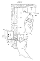
- FIGURE 1 shows one embodiment of an illustrative plug and play utility box mounted to a construction stud
- FIGURE 2 illustrates one example of the use of plug and play utility boxes in a premises environment
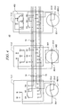
- FIGURES 3 , 4 , 5 and 6 show embodiments of schematics illustrating the plug and play nature of the wiring connections among permanently mounted utility boxes.
- FIGURE 7 shows one embodiment of a system having universal control.
- FIGURE 1 shows one embodiment 10 of an illustrative plug and play system using shell 11 inserted into a utility box , such as box 100.
- a utility box such as box 100.
- each box 100 would have a depth d no greater than (and presumably slightly less than) width w of the stud to which it is attached.
- the utility boxes can be constructed from any material, such as for example, metal or plastic. Such boxes would typically be mass-produced and sold in bulk.
- Shell 11 would have a depth less than "d" so as to form area 130 behind shell 11 and in front of back 103 of box 100.
- the wiring, such as wiring 14 and 15, that interconnects the boxes can be individual wires or pre-formed cables which are plugged into connector 12 or, when the shell is used, connected to connector(s) 12 (120) within space 130.
- This wiring typically would be added by an electrician after the box is fastened to a particular structural member with the utility wires entering the rear of box 100 and held in place, for example, by clamps 131.
- shell 11 When shell 11 is mated and secured within box 100 this wiring is hidden from view and away from fingers and tools.
- Shell 11 can be secured within box 11 in any well known manner, such as, for example, snaps, clips, screws, force fit and the like.
- One or more connectors 12-120 are positioned within shell 11 (or directly within box 100 when the shell is not used) such that contacts 13 of each such connector are open into area 102 of shell 11. This then allows a control device (not shown in FIGURE 1 ) to become mated, both electrically and physically, within box 100. Slots 101 of box 100 serve, if desired, to hold the mated control device within the utility box by mating with tabs on an inserted control device.
- connection electrical and/or control, and/or communications
- Connector 12 can be designed to snap in and out of shell 11 (or housing 100) which also serves to facilitate wiring to the connector. Note that while the connector is shown on the back wall of the shell, one or more connectors can be placed on any interior surface of the box and any surface of the shell, if desired.
- Device 300 is a switch (in this case a single-pole single-throw switch) contained within housing 21.
- Housing 21 (as is housing 301) has a physical design such that it fits within open area 102 of shell 11-1 (or within shell 11-2).
- the rear surface of housing 21 contains connector 22 having contacts 23 adapted for mating both physically and electrically with connector 12.
- Connector 22 is rigidly mounted to the rear surface of housing 21 as is connector 230 (if present).
- housing 21 is covered by, for example, face plate 201.
- Tabs 202 mate with slots 101 and are used to hold housing 21 firmly in position with respect to shell 11-1.
- the utility box can be designed to allow housing 22 to mate with it so that shell 11 need not be sturdy enough to hold the housing. This also allows the shell to be optimal, perhaps being used as in a retro fit situation.
- Shell 11 can be made of any material and typically would be of a plastic non-conductive material.
- FIGURE 3 shows one embodiment of a schematic, such as schematic 30, illustrating the plug and play nature of the wiring connections among shells 11-1, 11-2, 11-3 mounted within utility boxes.
- Terminals W, B, S1, S2, and S3, as well as other terminals are connected to wiring 14 and optionally 15 as shown.
- all the similarly lettered terminals are electrically common.
- the W terminal is connected to the white wire of the power grid while the B terminal is connected to the black wire of the grid.
- a 110V AC grid is assumed, but any power grid can be used.
- Switch 300 is shown connected to contacts 23-1 and 23-2 of connector 22 (shown in FIGURE 2 ) such that when switch 300 is mated with connector 12 ( FIGURE 2 ) of a junction box, such as shell 11-1, terminal 23-1 is electrically connected to terminal B of connector 12 while terminal 23-2 is electrically connected to terminal S1 of connector 12.
- switch 300 In operation, when a user operates switch 300, electrical current flows from the black wire of the power grid (terminal B shell 11-1) through switch 300 and via terminal S1 of shell 11-1 to terminal S1 ofshell-2 through cross connect bridge 320 to terminal S3 of shell 11-2 to device 301.
- the other side of device 301 is connected to the white wire of the power grid via terminal W of shell 11-2. This causes lamp 302 to go on and off following the switch operation of switch 300.
- Switch 300 is removed from shell 11-1 and replaced by three-way switch 400-1 which is wired as shown. This conversion then has the effect of allowing lamp 302 to be operated on or off from either switch 400-1 or 400-2 using the plug/play concepts described herein. Note that this conversion of functional operation occurred without the need for touching main wiring 14 or 15 and thus would not normally require the use of an electrician.
- FIGURE 6 shows the situation where device 501 becomes a switched outlet simply by inserting bridge 620 between outlet 501 and the connector of shell 11-3.
- switch 300 controls the on-off state of outlet 501, in a plug and play manner all without any changes to the power wiring of the premises.
- any number of different functions can be interchanged, such as, outlet socket, light socket, dimmer, motion detection switch, light-intensity detection switch, touch screen controller, telephone, alarm controller, etc.
- FIGURE 7 illustrates system 70 having universal control such that processor/communicator 71-1 associated with connector 230-1 in box 700-1 sends messages to one or more other processors, such as processor/communicator 71-N in box 700-N, to inform the system as to what type of device is plugged into box 700-1.
- Processor/communicator 71-N can be a control processor that then sends control signals to other devices, or processor/communicator 71-N can be a processor in each device for self control of the associated device.
Landscapes
- Engineering & Computer Science (AREA)
- Microelectronics & Electronic Packaging (AREA)
- Architecture (AREA)
- Civil Engineering (AREA)
- Structural Engineering (AREA)
- Details Of Connecting Devices For Male And Female Coupling (AREA)
- Connector Housings Or Holding Contact Members (AREA)
- Details Of Indoor Wiring (AREA)
Applications Claiming Priority (1)
| Application Number | Priority Date | Filing Date | Title |
|---|---|---|---|
| US11/683,335 US7497273B2 (en) | 2007-03-07 | 2007-03-07 | Plug and play utility control modules |
Publications (1)
| Publication Number | Publication Date |
|---|---|
| EP1968163A2 true EP1968163A2 (fr) | 2008-09-10 |
Family
ID=39564608
Family Applications (1)
| Application Number | Title | Priority Date | Filing Date |
|---|---|---|---|
| EP08250759A Withdrawn EP1968163A2 (fr) | 2007-03-07 | 2008-03-06 | Modules de contrôle d'utilité PnP |
Country Status (7)
| Country | Link |
|---|---|
| US (2) | US7497273B2 (fr) |
| EP (1) | EP1968163A2 (fr) |
| JP (1) | JP2008243813A (fr) |
| KR (1) | KR20080082532A (fr) |
| CN (1) | CN101282029A (fr) |
| AU (1) | AU2008200984A1 (fr) |
| CA (1) | CA2623091A1 (fr) |
Cited By (3)
| Publication number | Priority date | Publication date | Assignee | Title |
|---|---|---|---|---|
| GB2462336A (en) * | 2008-08-06 | 2010-02-10 | David Malone | Pattress box containing electrical terminals |
| CN105305237A (zh) * | 2015-11-19 | 2016-02-03 | 深圳市泰昂能源科技股份有限公司 | 变电站馈线柜及前维护馈线采集指示装置 |
| EP3123569A4 (fr) * | 2014-03-26 | 2018-05-09 | Elbex Video Ltd. | Boîtier de support intelligent pour commutateurs hybrides électriques, prises de courant et leurs combinaisons |
Families Citing this family (23)
| Publication number | Priority date | Publication date | Assignee | Title |
|---|---|---|---|---|
| US8575484B1 (en) | 2010-09-14 | 2013-11-05 | Cooper Technologies Company | Adjustable-depth ring assembly and method of installation |
| BR112014022518A2 (pt) | 2012-03-12 | 2017-10-03 | Norman R Byrne | Sistema de administração de energia elétrica, e método de controle da distribuição de energia elétrica dentre uma pluralidade de circuitos em um sistema elétrico |
| US8921694B2 (en) * | 2012-04-30 | 2014-12-30 | J Moss | Electrical fittings with integral cover plate and method of use thereof |
| US9325162B2 (en) * | 2012-04-30 | 2016-04-26 | J Moss | Ganged electrical fittings with integral cover plate and method of use thereof |
| CN103594985A (zh) * | 2013-11-13 | 2014-02-19 | 常熟市宝华建筑装璜材料有限公司 | 带温度监控器的接线盒 |
| US9246321B2 (en) * | 2014-03-25 | 2016-01-26 | Roger Fulton NEWILL | Wiring apparatus |
| JP6478373B2 (ja) * | 2014-06-19 | 2019-03-06 | 株式会社オカムラ | 椅子 |
| EP3089293B1 (fr) | 2015-04-30 | 2019-10-09 | Schneider Electric Industries SAS | Système d'installation électrique universel |
| US9564725B1 (en) | 2015-08-31 | 2017-02-07 | J Moss | Pluggable electrical receptacle and universal wall box and methods of use thereof |
| US11615625B2 (en) | 2015-08-31 | 2023-03-28 | Deako, Inc. | User-upgradeable load control network |
| WO2017040729A1 (fr) | 2015-08-31 | 2017-03-09 | Deako, Inc. | Système de contrôle d'attributs d'espaces de vie |
| BR102017021521A2 (pt) | 2016-10-07 | 2018-06-12 | Norman R. Byrne | Cabo de alimentação elétrica, e método de energização e desenergização seletiva de uma extremidade de saída de energia |
| US10050393B1 (en) * | 2017-05-25 | 2018-08-14 | Sony Interactive Entertainment LLC | Modular socket box |
| US10637223B2 (en) | 2017-06-06 | 2020-04-28 | Roger Fulton NEWILL | Wiring apparatus |
| KR101994352B1 (ko) * | 2017-08-23 | 2019-09-25 | 한국생산기술연구원 | 농업용 차량에 연결되는 동력인출장치의 제어방법 |
| CN109986318B (zh) * | 2017-12-29 | 2024-09-10 | 中国核动力研究设计院 | 一种超高压超临界二氧化碳流载干冰切割装置及方法 |
| US10923896B2 (en) * | 2018-10-31 | 2021-02-16 | Google Llc | Modular electrical control system |
| CN111355053B (zh) * | 2018-12-20 | 2025-03-11 | 夏敬懿 | 具有限制单向运动功能的导电钩爪 |
| CN109950445B (zh) * | 2019-03-28 | 2021-11-23 | 珠海博杰电子股份有限公司 | 电池盒装配方法 |
| US11424561B2 (en) | 2019-07-03 | 2022-08-23 | Norman R. Byrne | Outlet-level electrical energy management system |
| CN112310758A (zh) * | 2019-07-24 | 2021-02-02 | 深圳市云海物联科技有限公司 | 具有夜光功能的插座 |
| CN111917043B (zh) * | 2020-06-23 | 2022-05-31 | 祥兴电气有限公司 | 一种抽屉式电容补偿柜 |
| NL2031677B1 (en) | 2022-04-22 | 2023-11-07 | Isolectra B V | Plug-in module, set comprising said plug-in module and a wall box, and method for connecting the plug-in module to an end connector of a cable within the wall box |
Family Cites Families (28)
| Publication number | Priority date | Publication date | Assignee | Title |
|---|---|---|---|---|
| US1938309A (en) * | 1930-12-20 | 1933-12-05 | Emrys M Williams | Electrical outlet or switch |
| US2014444A (en) * | 1932-06-13 | 1935-09-17 | Edwards And Company Inc | Signaling device |
| US2908743A (en) * | 1956-11-30 | 1959-10-13 | Robert T Premoshis | Electrical outlet |
| US3860739A (en) * | 1971-08-03 | 1975-01-14 | Amp Inc | Method and apparatus for a wiring system utilizing wiring devices |
| US3879101A (en) * | 1973-12-04 | 1975-04-22 | George T Mckissic | Electric Plug-In Module |
| JPS6146632U (ja) | 1984-08-30 | 1986-03-28 | 株式会社トミー | パ−ソナルコンピユ−タ用プリンタバツフア |
| US4632476A (en) * | 1985-08-30 | 1986-12-30 | At&T Bell Laboratories | Terminal grounding unit |
| US4964058A (en) * | 1988-10-13 | 1990-10-16 | Square D Company | Power management and automation system |
| US4976631A (en) * | 1988-10-26 | 1990-12-11 | Harlow Jr Thomas L | Station bar |
| US5064387A (en) * | 1990-06-12 | 1991-11-12 | Thomas & Betts Corporation | Shielded electrical jack connector |
| US5424859A (en) * | 1992-09-24 | 1995-06-13 | Nippon Telegraph And Telephone Corp. | Transceiver for wireless in-building communication sytem |
| US5691898A (en) * | 1995-09-27 | 1997-11-25 | Immersion Human Interface Corp. | Safe and low cost computer peripherals with force feedback for consumer applications |
| US5735710A (en) * | 1995-10-17 | 1998-04-07 | Blaauboer; Wayne A. | Systems for connecting electrical components into an electrical wall box |
| US5825308A (en) * | 1996-11-26 | 1998-10-20 | Immersion Human Interface Corporation | Force feedback interface having isotonic and isometric functionality |
| CN1136632C (zh) * | 1998-03-26 | 2004-01-28 | 斯图尔脱联接体系股份有限公司 | 低形模块化电接插件和包括该电接插件的通信卡 |
| US6898618B1 (en) * | 2000-05-09 | 2005-05-24 | Sun Microsystems, Inc. | Client-specified display services in a distributed computing environment |
| DE10126947C2 (de) * | 2001-06-01 | 2003-06-26 | Deutsch Zentr Luft & Raumfahrt | Datenübertragungssystem mit einer lokalen Bake |
| WO2004066539A2 (fr) | 2003-01-15 | 2004-08-05 | Symbol Technologies, Inc. | Points d'accès sans fil de luminaires |
| US20040242290A1 (en) * | 2003-05-29 | 2004-12-02 | Keeling Michael C. | Broadband communication system |
| US6967565B2 (en) * | 2003-06-27 | 2005-11-22 | Hx Lifespace, Inc. | Building automation system |
| US6940016B1 (en) * | 2003-08-06 | 2005-09-06 | Desa Ip, Llc | Electrical rough-in box for low voltage transformer |
| US6932624B1 (en) * | 2004-02-05 | 2005-08-23 | Panamax | Modular signal and power connection device |
| DE102004042560A1 (de) | 2004-09-02 | 2006-03-09 | Siemens Ag | Einfach installierbares Relais zur Anpassung von Signalen für die Weiterübertragung |
| DE202004014389U1 (de) | 2004-09-16 | 2005-07-07 | Beck, Wilfried | WLAN Raum Access Point/Repeater mit Bedienelement und/oder Fernbedienung |
| US7232336B1 (en) * | 2005-04-20 | 2007-06-19 | Larry Douglas Evans | Multipurpose connection box for electrical modules |
| US20060276144A1 (en) * | 2005-06-02 | 2006-12-07 | Jack Campbell | Modular electrical component system combining power line voltage and low voltage elements |
| US7160147B1 (en) * | 2006-04-07 | 2007-01-09 | Stephan Gerard D | Electrical connection system |
| US7425677B2 (en) * | 2006-07-12 | 2008-09-16 | Advanced Currents Corp. | Closed electrical enclosure |
-
2007
- 2007-03-07 US US11/683,335 patent/US7497273B2/en not_active Expired - Fee Related
-
2008
- 2008-02-27 CA CA002623091A patent/CA2623091A1/fr not_active Abandoned
- 2008-02-29 AU AU2008200984A patent/AU2008200984A1/en not_active Abandoned
- 2008-03-06 EP EP08250759A patent/EP1968163A2/fr not_active Withdrawn
- 2008-03-06 CN CNA2008100065509A patent/CN101282029A/zh active Pending
- 2008-03-07 KR KR1020080021542A patent/KR20080082532A/ko not_active Withdrawn
- 2008-03-07 JP JP2008057956A patent/JP2008243813A/ja active Pending
-
2009
- 2009-02-24 US US12/391,586 patent/US20090235515A1/en not_active Abandoned
Cited By (4)
| Publication number | Priority date | Publication date | Assignee | Title |
|---|---|---|---|---|
| GB2462336A (en) * | 2008-08-06 | 2010-02-10 | David Malone | Pattress box containing electrical terminals |
| EP3123569A4 (fr) * | 2014-03-26 | 2018-05-09 | Elbex Video Ltd. | Boîtier de support intelligent pour commutateurs hybrides électriques, prises de courant et leurs combinaisons |
| CN105305237A (zh) * | 2015-11-19 | 2016-02-03 | 深圳市泰昂能源科技股份有限公司 | 变电站馈线柜及前维护馈线采集指示装置 |
| CN105305237B (zh) * | 2015-11-19 | 2017-09-05 | 深圳市泰昂能源科技股份有限公司 | 变电站馈线柜及前维护馈线采集指示装置 |
Also Published As
| Publication number | Publication date |
|---|---|
| CN101282029A (zh) | 2008-10-08 |
| US7497273B2 (en) | 2009-03-03 |
| KR20080082532A (ko) | 2008-09-11 |
| US20080219029A1 (en) | 2008-09-11 |
| CA2623091A1 (fr) | 2008-09-07 |
| AU2008200984A1 (en) | 2008-09-25 |
| JP2008243813A (ja) | 2008-10-09 |
| US20090235515A1 (en) | 2009-09-24 |
Similar Documents
| Publication | Publication Date | Title |
|---|---|---|
| US7497273B2 (en) | Plug and play utility control modules | |
| EP2697813B1 (fr) | Procédé et appareil pour combiner un relais de puissance ca et des capteurs de courant avec des dispositifs de câblage ca | |
| JP6971497B2 (ja) | 電気的自動化に使用するための、機械式ラッチリレー及びラッチリレーを有するハイブリッドスイッチ | |
| US6514652B2 (en) | Smart modular receptacle and system | |
| CN106233416B (zh) | 机械闩锁继电器和带有用于电气自动化中的闩锁继电器的混合开关 | |
| US6777611B2 (en) | Switch/power drop unit for modular wiring system | |
| CN105993058B (zh) | 带有用于住宅自动化中的spdt继电器组合的集成spdt或dpdt开关 | |
| US11615625B2 (en) | User-upgradeable load control network | |
| US9814121B2 (en) | Semi-wireless electric switch system | |
| CN118158009A (zh) | 用于安装和设置家庭自动化网格和网络的方法及其电气网格 | |
| US20260100562A1 (en) | Modular Electrical System with Interchangeable Functional Components | |
| JP7617544B2 (ja) | Usbコンセント | |
| CN118158011A (zh) | 触摸方法以及结构集成电气网格 | |
| HK40112571A (zh) | 触摸方法以及结构集成电气网格 | |
| HK40112212A (zh) | 触摸方法以及结构集成电气网格 | |
| KR20050061241A (ko) | 콘센트형 스위치 시스템 | |
| US20170365966A1 (en) | Interchangeable Lamp Fixtures | |
| AU2001261251A1 (en) | Improved electrical junciton box | |
| HK1226860A1 (en) | Mechanical latching relays and hybrid switches with latching relays for use in electrical automation | |
| HK1221076A1 (zh) | 积木式插座面板及用於积木式插座面板的层模块 | |
| HK1190239A (en) | Method and apparatus for combining ac power relay and current sensors with ac wiring devices | |
| HK1229528A1 (en) | Integrated spdt or dpdt switch with spdt relay combination for use in residence automation | |
| HK1190239B (en) | Method and apparatus for combining ac power relay and current sensors with ac wiring devices |
Legal Events
| Date | Code | Title | Description |
|---|---|---|---|
| PUAI | Public reference made under article 153(3) epc to a published international application that has entered the european phase |
Free format text: ORIGINAL CODE: 0009012 |
|
| AK | Designated contracting states |
Kind code of ref document: A2 Designated state(s): AT BE BG CH CY CZ DE DK EE ES FI FR GB GR HR HU IE IS IT LI LT LU LV MC MT NL NO PL PT RO SE SI SK TR |
|
| AX | Request for extension of the european patent |
Extension state: AL BA MK RS |
|
| STAA | Information on the status of an ep patent application or granted ep patent |
Free format text: STATUS: THE APPLICATION IS DEEMED TO BE WITHDRAWN |
|
| 18D | Application deemed to be withdrawn |
Effective date: 20101001 |