EP1968181A2 - Procédé de remise en circuit d'un moteur rotatif et commutation électrique destinée à exécuter le procédé - Google Patents
Procédé de remise en circuit d'un moteur rotatif et commutation électrique destinée à exécuter le procédé Download PDFInfo
- Publication number
- EP1968181A2 EP1968181A2 EP08003991A EP08003991A EP1968181A2 EP 1968181 A2 EP1968181 A2 EP 1968181A2 EP 08003991 A EP08003991 A EP 08003991A EP 08003991 A EP08003991 A EP 08003991A EP 1968181 A2 EP1968181 A2 EP 1968181A2
- Authority
- EP
- European Patent Office
- Prior art keywords
- voltage
- residual field
- supply voltage
- time
- field voltage
- Prior art date
- Legal status (The legal status is an assumption and is not a legal conclusion. Google has not performed a legal analysis and makes no representation as to the accuracy of the status listed.)
- Granted
Links
Images
Classifications
-
- H—ELECTRICITY
- H02—GENERATION; CONVERSION OR DISTRIBUTION OF ELECTRIC POWER
- H02P—CONTROL OR REGULATION OF ELECTRIC MOTORS, ELECTRIC GENERATORS OR DYNAMO-ELECTRIC CONVERTERS; CONTROLLING TRANSFORMERS, REACTORS OR CHOKE COILS
- H02P1/00—Arrangements for starting electric motors or dynamo-electric converters
- H02P1/02—Details of starting control
- H02P1/029—Restarting, e.g. after power failure
-
- H—ELECTRICITY
- H02—GENERATION; CONVERSION OR DISTRIBUTION OF ELECTRIC POWER
- H02P—CONTROL OR REGULATION OF ELECTRIC MOTORS, ELECTRIC GENERATORS OR DYNAMO-ELECTRIC CONVERTERS; CONTROLLING TRANSFORMERS, REACTORS OR CHOKE COILS
- H02P21/00—Arrangements or methods for the control of electric machines by vector control, e.g. by control of field orientation
- H02P21/14—Estimation or adaptation of machine parameters, e.g. flux, current or voltage
Definitions
- the invention relates to a method for reconnecting a three-phase motor (induction or synchronous motor) driving a working machine (eg gearbox turbocompressor) after disconnecting it from a supply voltage and in the presence of a residual field voltage induced by a rotor residual field and an electrical circuit for carrying out the same of the procedure.
- a three-phase motor induction or synchronous motor
- working machine eg gearbox turbocompressor
- the differences between the amplitudes, the frequencies and the phase shifts of the voltages of a supply network and a reserve network are constantly monitored Only if all differences comply with narrow limits, can the supply network be switched to the reserve network within a few milliseconds. If the conditions for a short-time switching are not met, then there is a long-term switching, where it is waited until the three-phase motor is braked so far that when the voltage is applied independently of the phase difference of the supply voltage and the residual field voltage an excessive torque stress can be excluded. Although the method of long-term switching ensures moderate shock moments, but has the disadvantage that the speed drops so much that thereby the work process is practically interrupted. Finally, there is also the risk that the reconnection in the case of a torsion or bending critical Speed of the powertrain occurs and caused by the switching large change moments, which endanger the components in the shaft train or even the automatic safety shutdown is activated.
- the invention has for its object to provide a method for reconnection of a three-phase motor after a separation of the same from a supply voltage in the presence of a residual field voltage induced by a rotor residual field, which allows for a minimization of torque stresses reconnection at an arbitrarily high residual field voltage.
- the object of the invention and solution of the problem is a method for reconnection of a three-phase motor after a separation thereof from a supply voltage in the presence of a residual field voltage induced by a rotor residual field, wherein the time profiles of the residual field voltage and the supply voltage are received, wherein the temporal progressions of the residual field voltage and the supply voltage precalculates the phase difference between the voltages and a time t s is determined at which the phase difference below a predetermined maximum value ⁇ max and wherein at a time interval corresponding to a predetermined switching time delay ⁇ s , before reaching the time t s on Switching command is triggered for the reconnection, so that the motor is connected to the supply voltage approximately at the time t s .
- a nearly bumpless connection of the motor can be carried out after a separation from a supply network, wherein usually the speed drop can be kept very low.
- the inventive method is based in particular on the finding that the angular velocity decreases starting from the mains frequency of the supply voltage as a result of the leakage of the motor after disconnection from the supply voltage, so that the residual field voltage and the supply voltage are approximately in phase when the motor is coasting at recurring times.
- a time t s can be determined in advance, to which the phase difference below a predetermined maximum value ⁇ max , wherein a switching command is triggered taking into account the switching time delay ⁇ s before reaching the time t s , so the voltage is applied approximately at the predicted time t s .
- the times of the zero crossings of the residual field voltage are determined, wherein the angular velocity and the change of the angular velocity of the residual field voltage are determined from the time intervals between the zero crossings.
- the determination of the zero crossings is from a metrological point of view, for example, with an analog comparator, particularly easy and reliable to implement and ensures the required within the scope of the inventive method accuracy.
- ⁇ R is the angular frequency of the residual field voltage at the time of the penultimate measurement
- d ⁇ R / dt is the angular frequency change of the residual field voltage at the time of the penultimate measurement.
- the time profile of the residual field voltage and the supply voltage and at least the amplitude A R of the residual field voltage can also be determined preferably, wherein at the fall of the amplitude of the residual field voltage below a predetermined maximum voltage A max of the switching command for the voltage application regardless of the phase relationship between the residual field voltage and the Supply voltage is triggered, in particular at a rapid deceleration of the three-phase motor, there is the possibility that even before the predicted falls below the predetermined phase difference ⁇ max a speed of the motor is achieved, regardless of the phase relationship between residual field voltage and supply voltage, the torque load is within an acceptable range, so that damage to the shaft train can be excluded.
- a reconnection is usually not critical.
- the current angular velocity ⁇ R of the residual field voltage is determined, it can be provided for predetermined frequency ranges, for example for frequency ranges in the vicinity of a system-critical rotational speed of the shaft train, that the reclosing be omitted even if the phase difference exceeds the predetermined maximum value to avoid damage ⁇ max or the amplitude A R of the residual field voltage falls below a predetermined maximum voltage A max .
- the predetermined frequency range is left, the reconnection of the three-phase motor takes place when the corresponding prerequisites have been met, ie at the next undershooting of the predetermined phase difference or when the predetermined maximum voltage is undershot.
- Three-phase motors for example, for the drive of turbocompressors, in practice often have a power of many kilowatts to several megawatts and are typically designed in three-stranded. Since the star point is consistently not accessible in high-voltage motors, the chained voltage (line voltage) between two lines, each with two measuring sensors, is usually measured as residual field voltage or supply voltage.
- the invention also provides an electrical circuit for carrying out the method according to the invention.
- the electrical circuit has a measured value detection, which can be connected to determine a time sequence of a residual field voltage and a supply voltage on the one hand to a three-phase motor and on the other hand to a supply network or a reserve network, a DC chopper for generating a switching pulse for a circuit breaker and a microcontroller, the precalculation the phase relationship between the residual field voltage and the supply voltage allows, on.
- the residual field voltage and the supply voltage typically have amplitudes of several thousand volts, so that the measured value acquisition preferably has probes for connection to the three-phase motor and the supply voltage, which serve as a voltage converter and the measured voltage, for example, in a range between -10 volts and +10 volts to reduce.
- the microcontroller which typically comprises an analog-to-digital converter, an analog comparator, a plurality of timers and at least one measured value memory for carrying out the method according to the invention, is preferably equipped with a standard programming interface for connection to a computer or a computer network, so that an easy configuration and In particular, an easy input of default values is possible.
- the electrical circuit can also have a status display and / or an interface for outputting status messages, so that a user can be directly informed of the status of the electrical circuit and the presence of a fault in the supply network. It is also conceivable that output status messages from a central machine or process control are recorded and further processed.
- a circuit breaker For renewed energization of the three-phase motor after a separation of the same from a supply voltage, a circuit breaker is typically provided which receives a switching pulse from the DC-DC converter.
- a switching pulse from the DC-DC converter.
- an output of the microcontroller is connected as a control signal to a preferably designed as a MOSFET field effect transistor (FET), which connects a separate input voltage to an output side of the DC adjuster.
- FET MOSFET field effect transistor
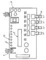
- FIGURE shows a rough schematic of a board on which the electrical circuit according to the invention is realized.
- the electrical circuit for carrying out the method according to the invention comprises a measured value acquisition 1, a microcontroller 2 and a DC converter 3 for generating a switching pulse for a circuit breaker.
- the circuit further comprises eight LEDs 4 as a status indicator 5 and 6 terminals for programming the microcontroller and to output status messages.
- the measured value acquisition 1 is connected via two probes, not shown, to two terminals of a three-phase motor and to two terminals of a supply voltage.
- the supply voltage is from a supply network or an additional reserve network, which the Operation of the engine in case of failure of the supply network allows, provided.
- the microcontroller 2 has eight digital outputs which are connected to the LED's 4 to indicate the current state.
- the first LED 4 is turned on at the start of the microcontroller 2 and indicates that the circuit is working.
- the second LED 4 is lit, the circuit is ready for a power failure.
- the LEDs 4 three to six indicate the expiration of a power failure after a disconnection of the motor from the supply voltage.
- the third LED 4 lights up when there is a mains interruption with respect to the supply network and goes out when the supply voltage is provided by a reserve network or again by the supply network.
- the fourth LED 4 lights up when the zero crossings of the supply voltage or of the residual field voltage are recorded by the measured value acquisition 1 to determine the time profiles of the phase of the residual field voltage and the supply voltage.
- the calculation of the time t s is based on the detection of the phase position of the residual field voltage at terminals of the motor and the supply voltage. To determine the phase relationship, the zero crossings of the supply voltage and the residual field voltage of a string or the chained voltage between two strings are determined. These voltages can be tapped directly in front of or behind the circuit breaker.
- the duration of the power interruption is first determined. For this purpose, first the duration of the power interruption is determined by the measured value acquisition 1. After the supply voltage is available again, a zero crossing of the supply voltage is determined by an analog comparator, wherein the phase of the supply voltage can be calculated in advance by determining this zero crossing, taking into account the mains frequency.
- the zero crossings of the residual field voltage are determined, wherein the angular velocity of the phase and the change of the angular velocity are determined from the time intervals between the zero crossings.
- the time t s is determined at which the phase difference falls below a predetermined maximum value ⁇ max of, for example, 20 °.
Landscapes
- Engineering & Computer Science (AREA)
- Power Engineering (AREA)
- Control Of Ac Motors In General (AREA)
- Control Of Eletrric Generators (AREA)
Applications Claiming Priority (1)
| Application Number | Priority Date | Filing Date | Title |
|---|---|---|---|
| DE102007011510A DE102007011510A1 (de) | 2007-03-09 | 2007-03-09 | Verfahren zur Wiederzuschaltung eines Drehstrommotors und elektrische Schaltung zur Durchführung des Verfahrens |
Publications (3)
| Publication Number | Publication Date |
|---|---|
| EP1968181A2 true EP1968181A2 (fr) | 2008-09-10 |
| EP1968181A3 EP1968181A3 (fr) | 2011-06-29 |
| EP1968181B1 EP1968181B1 (fr) | 2012-08-08 |
Family
ID=39581166
Family Applications (1)
| Application Number | Title | Priority Date | Filing Date |
|---|---|---|---|
| EP08003991A Not-in-force EP1968181B1 (fr) | 2007-03-09 | 2008-03-04 | Procédé de remise en circuit d'un moteur rotatif et commutation électrique destinée à exécuter le procédé |
Country Status (11)
| Country | Link |
|---|---|
| US (1) | US7868580B2 (fr) |
| EP (1) | EP1968181B1 (fr) |
| JP (1) | JP5559955B2 (fr) |
| KR (1) | KR20080082939A (fr) |
| CN (1) | CN101277083B (fr) |
| BR (1) | BRPI0800355B1 (fr) |
| CA (1) | CA2624775C (fr) |
| DE (1) | DE102007011510A1 (fr) |
| ES (1) | ES2393341T3 (fr) |
| MX (1) | MX2008003206A (fr) |
| RU (1) | RU2433519C2 (fr) |
Families Citing this family (3)
| Publication number | Priority date | Publication date | Assignee | Title |
|---|---|---|---|---|
| US8362735B2 (en) | 2011-03-07 | 2013-01-29 | Protective Energy Economizer Technology | Single phase motor energy economizer for regulating the use of electricity |
| US9125255B2 (en) * | 2012-05-03 | 2015-09-01 | Abl Ip Holding Llc | Networked architecture for system of lighting devices having sensors, for intelligent applications |
| US9137879B2 (en) | 2012-08-01 | 2015-09-15 | Abl Ip Holding Llc | Networked system of intelligent lighting devices with sharing of processing resources of the devices with other entities |
Citations (1)
| Publication number | Priority date | Publication date | Assignee | Title |
|---|---|---|---|---|
| WO2005112248A1 (fr) | 2004-05-07 | 2005-11-24 | Bay Controls, Inc. | Appareil et procede pour une periode de grace destinee a des moteurs a induction c.a. |
Family Cites Families (22)
| Publication number | Priority date | Publication date | Assignee | Title |
|---|---|---|---|---|
| US4465943A (en) * | 1983-04-29 | 1984-08-14 | Risberg Robert L | Uninterrupted power system with frequency and phase control |
| GB2165408B (en) * | 1984-10-03 | 1988-09-21 | Smith Ind Plc | Motor control systems and methods |
| JPS61244294A (ja) * | 1985-04-19 | 1986-10-30 | Toshiba Corp | 交流電動機の逆起電圧検出装置 |
| US4958117A (en) * | 1989-09-29 | 1990-09-18 | Allen-Bradley Company, Inc. | Frequency control based on sensing voltage fed to an induction motor |
| JP3191053B2 (ja) * | 1990-11-27 | 2001-07-23 | 株式会社日立製作所 | 回生インバータの制御方法 |
| DE4105698C2 (de) * | 1991-02-21 | 1997-06-19 | Eaw Relaistechnik Gmbh | Verfahren zum Betrieb eines dreipoligen Vakuumschützes mit Gruppenantrieb |
| JPH0522993A (ja) * | 1991-07-10 | 1993-01-29 | Meidensha Corp | インバータの同期切替制御方式 |
| RU2014720C1 (ru) * | 1992-01-10 | 1994-06-15 | Донецкий политехнический институт | Способ пуска и самозапуска синхронного двигателя |
| US5198734A (en) * | 1992-03-09 | 1993-03-30 | Marathon Oil Company | Method and means for stopping backspinning motor |
| RU2006167C1 (ru) * | 1992-05-14 | 1994-01-15 | Уральский научно-технологический комплекс | Устройство для пуска трехфазного синхронного электродвигателя |
| JP2773545B2 (ja) * | 1992-05-29 | 1998-07-09 | ノーリツ鋼機株式会社 | 回転画像焼付方法及び装置 |
| US5635772A (en) * | 1995-10-25 | 1997-06-03 | Eaton Corporation | Method and apparatus for transferring between electrical power sources which adaptively blocks transfer until load voltage decays to safe value |
| US5973465A (en) * | 1998-04-28 | 1999-10-26 | Toshiba International Corporation | Automotive restart control for submersible pump |
| SE513764C2 (sv) * | 1998-10-16 | 2000-10-30 | Atlas Copco Controls Ab | Metod för återstartning av en synkronmotor av permanentmagnettyp under restrotation |
| JP2000245190A (ja) * | 1999-02-23 | 2000-09-08 | Matsushita Electric Ind Co Ltd | ブラシレスモータの駆動制御装置及びその駆動制御方法 |
| JP2000341989A (ja) * | 1999-05-28 | 2000-12-08 | Hitachi Ltd | 誘導電動機の瞬時停電時の制御方法及び装置 |
| JP4139934B2 (ja) * | 1999-09-21 | 2008-08-27 | 株式会社安川電機 | 交流電動機の制御方法および制御装置 |
| JP3471269B2 (ja) * | 1999-12-17 | 2003-12-02 | 株式会社東芝 | 永久磁石形同期電動機の制御装置 |
| US7224557B2 (en) * | 2003-06-28 | 2007-05-29 | Eaton Corporation | Method and system of controlling asynchronous contactors for a multi-phase electric load |
| JP4060805B2 (ja) * | 2004-01-05 | 2008-03-12 | 三菱電機株式会社 | 電動機のトルク制御装置及び電動機のトルク制御方法及び電動機の回転子位置検出装置及び電動機の回転子位置検出方法及び密閉型圧縮機及び冷凍空調装置 |
| DE102004010482A1 (de) * | 2004-03-04 | 2005-09-22 | Seifert, Dieter, Dr.-Ing. | Verfahren zum Umschalten von Asynchronmaschinen mit geringstem Umschalt-Stromstoß und geringstem Umschalt-Drehmomentstoß |
| JP2006197745A (ja) * | 2005-01-14 | 2006-07-27 | Mitsubishi Electric Corp | 誘導電動機の制御装置 |
-
2007
- 2007-03-09 DE DE102007011510A patent/DE102007011510A1/de not_active Withdrawn
-
2008
- 2008-02-28 US US12/072,897 patent/US7868580B2/en active Active
- 2008-03-04 EP EP08003991A patent/EP1968181B1/fr not_active Not-in-force
- 2008-03-04 ES ES08003991T patent/ES2393341T3/es active Active
- 2008-03-06 RU RU2008108855/07A patent/RU2433519C2/ru active
- 2008-03-06 MX MX2008003206A patent/MX2008003206A/es active IP Right Grant
- 2008-03-07 JP JP2008057123A patent/JP5559955B2/ja not_active Expired - Fee Related
- 2008-03-07 CN CN2008100837171A patent/CN101277083B/zh active Active
- 2008-03-07 CA CA2624775A patent/CA2624775C/fr active Active
- 2008-03-10 BR BRPI0800355A patent/BRPI0800355B1/pt not_active IP Right Cessation
- 2008-03-10 KR KR1020080022124A patent/KR20080082939A/ko not_active Ceased
Patent Citations (1)
| Publication number | Priority date | Publication date | Assignee | Title |
|---|---|---|---|---|
| WO2005112248A1 (fr) | 2004-05-07 | 2005-11-24 | Bay Controls, Inc. | Appareil et procede pour une periode de grace destinee a des moteurs a induction c.a. |
Non-Patent Citations (2)
| Title |
|---|
| "Archiv für Elektrotechnik", vol. 71, 1988, pages: 399 - 411 |
| ELEKTRIE, vol. 46, 1992, pages 456 - 460 |
Also Published As
| Publication number | Publication date |
|---|---|
| RU2008108855A (ru) | 2009-09-20 |
| JP2008228562A (ja) | 2008-09-25 |
| MX2008003206A (es) | 2009-02-25 |
| US20080218117A1 (en) | 2008-09-11 |
| RU2433519C2 (ru) | 2011-11-10 |
| ES2393341T3 (es) | 2012-12-20 |
| DE102007011510A1 (de) | 2008-09-11 |
| CN101277083B (zh) | 2010-09-08 |
| CN101277083A (zh) | 2008-10-01 |
| CA2624775C (fr) | 2012-10-02 |
| HK1123642A1 (en) | 2009-06-19 |
| BRPI0800355A2 (pt) | 2013-09-03 |
| EP1968181B1 (fr) | 2012-08-08 |
| CA2624775A1 (fr) | 2008-09-09 |
| BRPI0800355B1 (pt) | 2018-08-28 |
| US7868580B2 (en) | 2011-01-11 |
| JP5559955B2 (ja) | 2014-07-23 |
| KR20080082939A (ko) | 2008-09-12 |
| EP1968181A3 (fr) | 2011-06-29 |
Similar Documents
| Publication | Publication Date | Title |
|---|---|---|
| DE102018124641B4 (de) | Motorantriebsvorrichtung, die eine Ausfallerfassungsfunktion aufweist | |
| DE102016111395B4 (de) | Motorantriebsvorrichtung mit Mittel zum Erfassen anomaler Wärmeerzeugung in Anfangsladeschaltung | |
| DE102007014728A1 (de) | Verfahren und Vorrichtung zum Betrieb einer doppeltgespeisten Asynchronmaschine bei transienten Netzspannungsänderungen | |
| EP3469705A1 (fr) | Procédé et dispositif de protection pour limiter le couple d'une machine électrique | |
| EP2962388B1 (fr) | Procédé de reconnaissance de glissement de pôle | |
| EP2509214B1 (fr) | Procédé de mise en service du commutateur de commande électronique d'un moteur électrique et agencement de commutation correspondant | |
| EP2283571A2 (fr) | Procede et dispositif pour l'arret fiable d'un entrainement electrique | |
| EP1968181B1 (fr) | Procédé de remise en circuit d'un moteur rotatif et commutation électrique destinée à exécuter le procédé | |
| DE69936222T2 (de) | System und verfahren zum schutz eines elektromotors und dessen ansteuerschaltung, und ein elektromotor | |
| WO2011018302A1 (fr) | Procédé permettant de surveiller un état d'entraînement d'un moteur électrique | |
| WO2011157472A1 (fr) | Montage pour déterminer une variation de tension de potentiels de conducteur dans un réseau électrique non mis à la terre | |
| EP3609032B1 (fr) | Procédé de détection d'une erreur de phase de moteur sur un dispositif moteur et circuit d'entraînement permettant d'entraîner un moteur à commutation électronique | |
| EP2491410B1 (fr) | Appareil électrique pouvant être alimenté à partir d'un réseau électrique à courant alternatif et procédé de détection d'erreur | |
| EP2998753B1 (fr) | Dispositif de surveillance d'une machine electrique, dispositif de commande et procede | |
| EP2965421B1 (fr) | Détection de la rupture du fil pour faire fonctionner un moteur à courant continu sans balais | |
| EP2774266B1 (fr) | Procédé et dispositif pour faire fonctionner une machine électrique à commutation électronique en cas de défaillance | |
| EP2759055B1 (fr) | Procédé et dispositif pour faire fonctionner des moteurs synchrones | |
| DE102015003446A1 (de) | Versorgung eines Kraftfahrzeugs mit Spannungsprüfung | |
| DE3324542A1 (de) | Inverterschaltung/wechselrichterschaltung | |
| EP1798559A2 (fr) | Procédé et dispositif pour déterminer la vitesse de rotation d'une machine électrique | |
| BE1027539B1 (de) | Verfahren und Vorrichtung zur Ermittlung der Drehrichtung eines Drehfeldes sowie Hybrid-Motorstarter | |
| EP2654155B1 (fr) | Convertisseur de courant, tout comme procédé destiné au fonctionnement d'un convertisseur de courant | |
| DE102010030083A1 (de) | Schaltungsanordnung zur Bestimmung einer Spannungsschwankung von Leiterpotentialen in einem ungeerdeten elektrischen Netz | |
| DE102009011254A1 (de) | Frequenzrichter und Verfahren zur Herstellung eines solchen | |
| EP2670042B1 (fr) | Convertisseur doté d'une mesure de tension de circuit intermédiaire redondante tout comme procédé destiné au fonctionnement d'un convertisseur de courant |
Legal Events
| Date | Code | Title | Description |
|---|---|---|---|
| PUAI | Public reference made under article 153(3) epc to a published international application that has entered the european phase |
Free format text: ORIGINAL CODE: 0009012 |
|
| AK | Designated contracting states |
Kind code of ref document: A2 Designated state(s): AT BE BG CH CY CZ DE DK EE ES FI FR GB GR HR HU IE IS IT LI LT LU LV MC MT NL NO PL PT RO SE SI SK TR |
|
| AX | Request for extension of the european patent |
Extension state: AL BA MK RS |
|
| PUAL | Search report despatched |
Free format text: ORIGINAL CODE: 0009013 |
|
| AK | Designated contracting states |
Kind code of ref document: A3 Designated state(s): AT BE BG CH CY CZ DE DK EE ES FI FR GB GR HR HU IE IS IT LI LT LU LV MC MT NL NO PL PT RO SE SI SK TR |
|
| AX | Request for extension of the european patent |
Extension state: AL BA MK RS |
|
| 17P | Request for examination filed |
Effective date: 20110713 |
|
| AKX | Designation fees paid |
Designated state(s): AT BE BG CH CY CZ DE DK EE ES FI FR GB GR HR HU IE IS IT LI LT LU LV MC MT NL NO PL PT RO SE SI SK TR |
|
| GRAP | Despatch of communication of intention to grant a patent |
Free format text: ORIGINAL CODE: EPIDOSNIGR1 |
|
| GRAS | Grant fee paid |
Free format text: ORIGINAL CODE: EPIDOSNIGR3 |
|
| GRAA | (expected) grant |
Free format text: ORIGINAL CODE: 0009210 |
|
| AK | Designated contracting states |
Kind code of ref document: B1 Designated state(s): AT BE BG CH CY CZ DE DK EE ES FI FR GB GR HR HU IE IS IT LI LT LU LV MC MT NL NO PL PT RO SE SI SK TR |
|
| REG | Reference to a national code |
Ref country code: GB Ref legal event code: FG4D Free format text: NOT ENGLISH |
|
| REG | Reference to a national code |
Ref country code: CH Ref legal event code: EP Ref country code: AT Ref legal event code: REF Ref document number: 570191 Country of ref document: AT Kind code of ref document: T Effective date: 20120815 |
|
| REG | Reference to a national code |
Ref country code: IE Ref legal event code: FG4D Free format text: LANGUAGE OF EP DOCUMENT: GERMAN |
|
| BECA | Be: change of holder's address |
Owner name: SCHLEHENWEG 15, D-50999 KOELN Effective date: 20120808 Owner name: ATLAS COPCO ENERGAS G.M.B.H. Effective date: 20120808 |
|
| REG | Reference to a national code |
Ref country code: DE Ref legal event code: R096 Ref document number: 502008007854 Country of ref document: DE Effective date: 20121004 |
|
| RAP2 | Party data changed (patent owner data changed or rights of a patent transferred) |
Owner name: ATLAS COPCO ENERGAS GMBH |
|
| REG | Reference to a national code |
Ref country code: NL Ref legal event code: T3 |
|
| REG | Reference to a national code |
Ref country code: SE Ref legal event code: TRGR |
|
| REG | Reference to a national code |
Ref country code: ES Ref legal event code: FG2A Ref document number: 2393341 Country of ref document: ES Kind code of ref document: T3 Effective date: 20121220 |
|
| REG | Reference to a national code |
Ref country code: FR Ref legal event code: CA Effective date: 20121205 |
|
| REG | Reference to a national code |
Ref country code: LT Ref legal event code: MG4D Effective date: 20120808 |
|
| PG25 | Lapsed in a contracting state [announced via postgrant information from national office to epo] |
Ref country code: IS Free format text: LAPSE BECAUSE OF FAILURE TO SUBMIT A TRANSLATION OF THE DESCRIPTION OR TO PAY THE FEE WITHIN THE PRESCRIBED TIME-LIMIT Effective date: 20121208 Ref country code: HR Free format text: LAPSE BECAUSE OF FAILURE TO SUBMIT A TRANSLATION OF THE DESCRIPTION OR TO PAY THE FEE WITHIN THE PRESCRIBED TIME-LIMIT Effective date: 20120808 Ref country code: CY Free format text: LAPSE BECAUSE OF FAILURE TO SUBMIT A TRANSLATION OF THE DESCRIPTION OR TO PAY THE FEE WITHIN THE PRESCRIBED TIME-LIMIT Effective date: 20120808 Ref country code: LT Free format text: LAPSE BECAUSE OF FAILURE TO SUBMIT A TRANSLATION OF THE DESCRIPTION OR TO PAY THE FEE WITHIN THE PRESCRIBED TIME-LIMIT Effective date: 20120808 Ref country code: NO Free format text: LAPSE BECAUSE OF FAILURE TO SUBMIT A TRANSLATION OF THE DESCRIPTION OR TO PAY THE FEE WITHIN THE PRESCRIBED TIME-LIMIT Effective date: 20121108 |
|
| PG25 | Lapsed in a contracting state [announced via postgrant information from national office to epo] |
Ref country code: LV Free format text: LAPSE BECAUSE OF FAILURE TO SUBMIT A TRANSLATION OF THE DESCRIPTION OR TO PAY THE FEE WITHIN THE PRESCRIBED TIME-LIMIT Effective date: 20120808 Ref country code: GR Free format text: LAPSE BECAUSE OF FAILURE TO SUBMIT A TRANSLATION OF THE DESCRIPTION OR TO PAY THE FEE WITHIN THE PRESCRIBED TIME-LIMIT Effective date: 20121109 Ref country code: PT Free format text: LAPSE BECAUSE OF FAILURE TO SUBMIT A TRANSLATION OF THE DESCRIPTION OR TO PAY THE FEE WITHIN THE PRESCRIBED TIME-LIMIT Effective date: 20121210 Ref country code: PL Free format text: LAPSE BECAUSE OF FAILURE TO SUBMIT A TRANSLATION OF THE DESCRIPTION OR TO PAY THE FEE WITHIN THE PRESCRIBED TIME-LIMIT Effective date: 20120808 Ref country code: SI Free format text: LAPSE BECAUSE OF FAILURE TO SUBMIT A TRANSLATION OF THE DESCRIPTION OR TO PAY THE FEE WITHIN THE PRESCRIBED TIME-LIMIT Effective date: 20120808 |
|
| PG25 | Lapsed in a contracting state [announced via postgrant information from national office to epo] |
Ref country code: DK Free format text: LAPSE BECAUSE OF FAILURE TO SUBMIT A TRANSLATION OF THE DESCRIPTION OR TO PAY THE FEE WITHIN THE PRESCRIBED TIME-LIMIT Effective date: 20120808 Ref country code: EE Free format text: LAPSE BECAUSE OF FAILURE TO SUBMIT A TRANSLATION OF THE DESCRIPTION OR TO PAY THE FEE WITHIN THE PRESCRIBED TIME-LIMIT Effective date: 20120808 Ref country code: RO Free format text: LAPSE BECAUSE OF FAILURE TO SUBMIT A TRANSLATION OF THE DESCRIPTION OR TO PAY THE FEE WITHIN THE PRESCRIBED TIME-LIMIT Effective date: 20120808 Ref country code: CZ Free format text: LAPSE BECAUSE OF FAILURE TO SUBMIT A TRANSLATION OF THE DESCRIPTION OR TO PAY THE FEE WITHIN THE PRESCRIBED TIME-LIMIT Effective date: 20120808 |
|
| PG25 | Lapsed in a contracting state [announced via postgrant information from national office to epo] |
Ref country code: SK Free format text: LAPSE BECAUSE OF FAILURE TO SUBMIT A TRANSLATION OF THE DESCRIPTION OR TO PAY THE FEE WITHIN THE PRESCRIBED TIME-LIMIT Effective date: 20120808 |
|
| PLBE | No opposition filed within time limit |
Free format text: ORIGINAL CODE: 0009261 |
|
| STAA | Information on the status of an ep patent application or granted ep patent |
Free format text: STATUS: NO OPPOSITION FILED WITHIN TIME LIMIT |
|
| 26N | No opposition filed |
Effective date: 20130510 |
|
| PG25 | Lapsed in a contracting state [announced via postgrant information from national office to epo] |
Ref country code: BG Free format text: LAPSE BECAUSE OF FAILURE TO SUBMIT A TRANSLATION OF THE DESCRIPTION OR TO PAY THE FEE WITHIN THE PRESCRIBED TIME-LIMIT Effective date: 20121108 |
|
| REG | Reference to a national code |
Ref country code: DE Ref legal event code: R097 Ref document number: 502008007854 Country of ref document: DE Effective date: 20130510 |
|
| PG25 | Lapsed in a contracting state [announced via postgrant information from national office to epo] |
Ref country code: MC Free format text: LAPSE BECAUSE OF NON-PAYMENT OF DUE FEES Effective date: 20130331 |
|
| REG | Reference to a national code |
Ref country code: CH Ref legal event code: PL |
|
| REG | Reference to a national code |
Ref country code: IE Ref legal event code: MM4A |
|
| PG25 | Lapsed in a contracting state [announced via postgrant information from national office to epo] |
Ref country code: CH Free format text: LAPSE BECAUSE OF NON-PAYMENT OF DUE FEES Effective date: 20130331 Ref country code: IE Free format text: LAPSE BECAUSE OF NON-PAYMENT OF DUE FEES Effective date: 20130304 Ref country code: LI Free format text: LAPSE BECAUSE OF NON-PAYMENT OF DUE FEES Effective date: 20130331 |
|
| REG | Reference to a national code |
Ref country code: AT Ref legal event code: MM01 Ref document number: 570191 Country of ref document: AT Kind code of ref document: T Effective date: 20130304 |
|
| PG25 | Lapsed in a contracting state [announced via postgrant information from national office to epo] |
Ref country code: MT Free format text: LAPSE BECAUSE OF FAILURE TO SUBMIT A TRANSLATION OF THE DESCRIPTION OR TO PAY THE FEE WITHIN THE PRESCRIBED TIME-LIMIT Effective date: 20120808 |
|
| PG25 | Lapsed in a contracting state [announced via postgrant information from national office to epo] |
Ref country code: AT Free format text: LAPSE BECAUSE OF NON-PAYMENT OF DUE FEES Effective date: 20130304 |
|
| PG25 | Lapsed in a contracting state [announced via postgrant information from national office to epo] |
Ref country code: TR Free format text: LAPSE BECAUSE OF FAILURE TO SUBMIT A TRANSLATION OF THE DESCRIPTION OR TO PAY THE FEE WITHIN THE PRESCRIBED TIME-LIMIT Effective date: 20120808 |
|
| PG25 | Lapsed in a contracting state [announced via postgrant information from national office to epo] |
Ref country code: LU Free format text: LAPSE BECAUSE OF NON-PAYMENT OF DUE FEES Effective date: 20130304 Ref country code: HU Free format text: LAPSE BECAUSE OF FAILURE TO SUBMIT A TRANSLATION OF THE DESCRIPTION OR TO PAY THE FEE WITHIN THE PRESCRIBED TIME-LIMIT; INVALID AB INITIO Effective date: 20080304 |
|
| REG | Reference to a national code |
Ref country code: FR Ref legal event code: PLFP Year of fee payment: 9 |
|
| REG | Reference to a national code |
Ref country code: FR Ref legal event code: PLFP Year of fee payment: 10 |
|
| REG | Reference to a national code |
Ref country code: FR Ref legal event code: PLFP Year of fee payment: 11 |
|
| PGFP | Annual fee paid to national office [announced via postgrant information from national office to epo] |
Ref country code: GB Payment date: 20220321 Year of fee payment: 15 Ref country code: FI Payment date: 20220322 Year of fee payment: 15 Ref country code: DE Payment date: 20220216 Year of fee payment: 15 |
|
| PGFP | Annual fee paid to national office [announced via postgrant information from national office to epo] |
Ref country code: SE Payment date: 20220321 Year of fee payment: 15 Ref country code: NL Payment date: 20220321 Year of fee payment: 15 Ref country code: IT Payment date: 20220322 Year of fee payment: 15 Ref country code: FR Payment date: 20220322 Year of fee payment: 15 Ref country code: BE Payment date: 20220321 Year of fee payment: 15 |
|
| PGFP | Annual fee paid to national office [announced via postgrant information from national office to epo] |
Ref country code: ES Payment date: 20220527 Year of fee payment: 15 |
|
| REG | Reference to a national code |
Ref country code: DE Ref legal event code: R119 Ref document number: 502008007854 Country of ref document: DE |
|
| PG25 | Lapsed in a contracting state [announced via postgrant information from national office to epo] |
Ref country code: FI Free format text: LAPSE BECAUSE OF NON-PAYMENT OF DUE FEES Effective date: 20230304 |
|
| REG | Reference to a national code |
Ref country code: SE Ref legal event code: EUG |
|
| REG | Reference to a national code |
Ref country code: NL Ref legal event code: MM Effective date: 20230401 |
|
| GBPC | Gb: european patent ceased through non-payment of renewal fee |
Effective date: 20230304 |
|
| REG | Reference to a national code |
Ref country code: BE Ref legal event code: MM Effective date: 20230331 |
|
| PG25 | Lapsed in a contracting state [announced via postgrant information from national office to epo] |
Ref country code: NL Free format text: LAPSE BECAUSE OF NON-PAYMENT OF DUE FEES Effective date: 20230401 |
|
| PG25 | Lapsed in a contracting state [announced via postgrant information from national office to epo] |
Ref country code: GB Free format text: LAPSE BECAUSE OF NON-PAYMENT OF DUE FEES Effective date: 20230304 |
|
| PG25 | Lapsed in a contracting state [announced via postgrant information from national office to epo] |
Ref country code: SE Free format text: LAPSE BECAUSE OF NON-PAYMENT OF DUE FEES Effective date: 20230305 Ref country code: GB Free format text: LAPSE BECAUSE OF NON-PAYMENT OF DUE FEES Effective date: 20230304 Ref country code: FR Free format text: LAPSE BECAUSE OF NON-PAYMENT OF DUE FEES Effective date: 20230331 Ref country code: DE Free format text: LAPSE BECAUSE OF NON-PAYMENT OF DUE FEES Effective date: 20231003 |
|
| PG25 | Lapsed in a contracting state [announced via postgrant information from national office to epo] |
Ref country code: BE Free format text: LAPSE BECAUSE OF NON-PAYMENT OF DUE FEES Effective date: 20230331 |
|
| PG25 | Lapsed in a contracting state [announced via postgrant information from national office to epo] |
Ref country code: ES Free format text: LAPSE BECAUSE OF NON-PAYMENT OF DUE FEES Effective date: 20230305 |
|
| REG | Reference to a national code |
Ref country code: ES Ref legal event code: FD2A Effective date: 20240426 |
|
| PG25 | Lapsed in a contracting state [announced via postgrant information from national office to epo] |
Ref country code: IT Free format text: LAPSE BECAUSE OF NON-PAYMENT OF DUE FEES Effective date: 20230304 Ref country code: ES Free format text: LAPSE BECAUSE OF NON-PAYMENT OF DUE FEES Effective date: 20230305 |