EP1968210A1 - Réseau d'antennes de toit pour système à diversité de phases - Google Patents
Réseau d'antennes de toit pour système à diversité de phases Download PDFInfo
- Publication number
- EP1968210A1 EP1968210A1 EP07004814A EP07004814A EP1968210A1 EP 1968210 A1 EP1968210 A1 EP 1968210A1 EP 07004814 A EP07004814 A EP 07004814A EP 07004814 A EP07004814 A EP 07004814A EP 1968210 A1 EP1968210 A1 EP 1968210A1
- Authority
- EP
- European Patent Office
- Prior art keywords
- vehicle
- antenna
- roof
- diversity
- vehicle roof
- Prior art date
- Legal status (The legal status is an assumption and is not a legal conclusion. Google has not performed a legal analysis and makes no representation as to the accuracy of the status listed.)
- Ceased
Links
Images

Classifications
-
- H—ELECTRICITY
- H01—ELECTRIC ELEMENTS
- H01Q—ANTENNAS, i.e. RADIO AERIALS
- H01Q1/00—Details of, or arrangements associated with, antennas
- H01Q1/27—Adaptation for use in or on movable bodies
- H01Q1/32—Adaptation for use in or on road or rail vehicles
- H01Q1/325—Adaptation for use in or on road or rail vehicles characterised by the location of the antenna on the vehicle
- H01Q1/3275—Adaptation for use in or on road or rail vehicles characterised by the location of the antenna on the vehicle mounted on a horizontal surface of the vehicle, e.g. on roof, hood, trunk
-
- H—ELECTRICITY
- H01—ELECTRIC ELEMENTS
- H01Q—ANTENNAS, i.e. RADIO AERIALS
- H01Q9/00—Electrically-short antennas having dimensions not more than twice the operating wavelength and consisting of conductive active radiating elements
- H01Q9/04—Resonant antennas
- H01Q9/16—Resonant antennas with feed intermediate between the extremities of the antenna, e.g. centre-fed dipole
-
- H—ELECTRICITY
- H04—ELECTRIC COMMUNICATION TECHNIQUE
- H04B—TRANSMISSION
- H04B7/00—Radio transmission systems, i.e. using radiation field
- H04B7/02—Diversity systems; Multi-antenna system, i.e. transmission or reception using multiple antennas
- H04B7/04—Diversity systems; Multi-antenna system, i.e. transmission or reception using multiple antennas using two or more spaced independent antennas
- H04B7/08—Diversity systems; Multi-antenna system, i.e. transmission or reception using multiple antennas using two or more spaced independent antennas at the receiving station
- H04B7/0837—Diversity systems; Multi-antenna system, i.e. transmission or reception using multiple antennas using two or more spaced independent antennas at the receiving station using pre-detection combining
- H04B7/084—Equal gain combining, only phase adjustments
Definitions
- the invention generally relates to an antenna configuration for a phase diversity system, and in particular to an FM phase diversity system mounted on a vehicle.
- Diversity schemes are used to reduce multi-path interference, improve fringe area reception and therefore enhance sound quality. To achieve this, at least two antenna elements are needed in any diversity receiving system to improve reception quality. Apart from for polarization diversity, these antennas need to be a reasonable distance apart to reap the benefits of diversity reception. This means that a significant amount of space is needed and has to be made available for the antenna configuration.
- the size and placement of the antenna have become an important factor in automobile antenna design because the antenna should be mounted on a limited area of the automobile body. A smaller size can improve the esthetics of a vehicle.
- the commercial FM frequency band is from 65.9 - 108 MHz, for different regions worldwide. At these frequencies, the entire body of the car is on the order of a wavelength (approximately 3m). The entire vehicle structure strongly influences the performance of the automobile antenna. Antenna operating frequencies, input impedance, gain patterns, and polarization are the main design parameters for any antennas.
- FM phase diversity antenna configurations are mainly mounted in the rear window or the wing of mass-production vehicles. These positions have several disadvantages. Firstly, the vehicle itself may shadow the antennas and therefore reception is degraded. Also antennas in the rear window, wing or bumper have directional characteristics that can lead to a worse performance of the phase diversity receiving system. Also, if an antenna element should become faulty, the whole rear window would have to be replaced at considerable cost.
- the current FM reception antennas mounted on the exterior of cars make the wind resistance of cars higher and can often easily be broken off. Caution has to be exercised especially in car washes.
- the present invention has been made in consideration of the situation above and has as its object to improve FM reception in a vehicle while having unobtrusive antennas.
- the present invention provides a vehicle roof diversity antenna system for use on a vehicle, the vehicle roof diversity antenna system comprising at least two antenna elements, wherein at least one antenna element of the at least two antenna elements is parallel to a roof surface on top of the vehicle.
- the at least two antenna elements are adapted to receive frequency modulated signals.
- the at least two antenna elements are adapted to receive signals in the FM frequency range.
- the at least two antenna elements have a length of half a wavelength.
- the at least two antenna elements are adapted to receive phase diversity signals.
- the at least two antenna elements are dipoles.
- the at least two antenna elements are active antennas.
- the at least one antenna element is attached to a roof rail.
- the at least one antenna element is integrated in a roof rail.
- roof rails are adapted to operate as antenna elements.
- the vehicle is a sports utility vehicle or an off-road vehicle or an estate car.
- Phase diversity technology is based on a fact that fading of received signal at each antenna element is independent of each other.
- phase diversity The key part of the phase diversity is that the signal at each antenna element is independent of each other because the signal at each antenna element consists of a large number of signals. This is because the interfering terms consist of M-1 terms of which the incident angles are all independent such that the magnitude of the received signal at each element, which is determined by a vector sum of M signal components, must be determined in a random fashion.
- a phase diversity system combines baseband signals or IF (intermediate frequency) signals received by two or more antennas 40_1, 40_2 .. 40_N.
- IF intermediate frequency
- Figure 4 an example of a phase diversity system with two antennas 40_1, 40_2 is shown. Both phase and amplitude or only the phases of signals x1 and x2 are adaptively changed.
- Figure 4 illustrates only the principle of phase diversity and one of the possible implementations. It is not the only possible solution: phase rotation and amplitude amplification/attenuation of signals x1 and x2 can be performed either in the analog or in the digital domain.
- the signal is received by antennas 40_1 and 40_2 and combined in adder 44 after being weighted in weighting sections 42_1 and 42_2.
- the weighting of signals x1 and x2 is ascertained by feedback from after adder 44 and from the received signals x1 and x2 in an adaptive algorithm section 46.
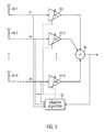
- FIG. 5 the principle of phase diversity with N antennas 40_1, 40_2 .. 40_N is illustrated. Similarly to the two antenna case illustrated in Fig. 4 , Fig. 5 shows the case with N antennas 40_1 .. 40_N.
- Each of the received signals x1 .. xN is weighted in a weighting section 42_1 .. 42_N before being combined in adder 50. The weighting depends on the feedback from adder 50 and the received signals x1 .. xN and is set by adaptive algorithm section 52.
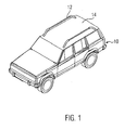
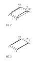
- At least one antenna is attached to the left roof railing 12_1 and at least another antenna is attached to the right 12_2 roof railing to provide an antenna diversity reception system.
- At least one antenna is integrated in the left roof railing and at least another antenna is integrated in the right roof railing to provide an antenna diversity reception system.
- the antennas are spatially separated further than in the current mass produced vehicles with the antennas in the rear window. This separation of about half a wavelength at FM is an advantage in phase diversity systems, as explained above. Also the coupling between the two antenna elements is less in the present invention than when the antennas are closer to each other, as in the case of having the antenna elements integrated in the rear window.
- one antenna element is attached to or integrated in one of the roof railings, whereas the other antenna element can be in one of the usual places, such as integrated in the rear view window.
- the two antenna elements then still have a large enough separation to allow for phase diversity.
- the attachment of the at least one antenna to the roof rails can be carried out by fastening the antenna elements to the rails by adhesive.
- the antenna elements are fastened to the roof rails by mechanical means, such as straps, or bolting or screwing them thereto.
- the antenna is an active antenna.
- the antenna is a passive antenna.
- the roof rails are antenna elements themselves. This can be achieved by making the roof rails from the appropriate material, such as aluminium.
- phase diversity reception antennas attached to, integrated in or as roof rails are a reduced mass, it complements the vehicle styling, elimination of loss or theft of antennas and elimination of antenna wind noise.
Landscapes
- Engineering & Computer Science (AREA)
- Computer Networks & Wireless Communication (AREA)
- Signal Processing (AREA)
- Remote Sensing (AREA)
- Radio Transmission System (AREA)
Priority Applications (2)
| Application Number | Priority Date | Filing Date | Title |
|---|---|---|---|
| EP07004814A EP1968210A1 (fr) | 2007-03-08 | 2007-03-08 | Réseau d'antennes de toit pour système à diversité de phases |
| US12/043,553 US7696939B2 (en) | 2007-03-08 | 2008-03-06 | Roof antenna array for phase diversity system |
Applications Claiming Priority (1)
| Application Number | Priority Date | Filing Date | Title |
|---|---|---|---|
| EP07004814A EP1968210A1 (fr) | 2007-03-08 | 2007-03-08 | Réseau d'antennes de toit pour système à diversité de phases |
Publications (1)
| Publication Number | Publication Date |
|---|---|
| EP1968210A1 true EP1968210A1 (fr) | 2008-09-10 |
Family
ID=37907240
Family Applications (1)
| Application Number | Title | Priority Date | Filing Date |
|---|---|---|---|
| EP07004814A Ceased EP1968210A1 (fr) | 2007-03-08 | 2007-03-08 | Réseau d'antennes de toit pour système à diversité de phases |
Country Status (2)
| Country | Link |
|---|---|
| US (1) | US7696939B2 (fr) |
| EP (1) | EP1968210A1 (fr) |
Cited By (2)
| Publication number | Priority date | Publication date | Assignee | Title |
|---|---|---|---|---|
| FR2952490A1 (fr) * | 2009-11-09 | 2011-05-13 | Peugeot Citroen Automobiles Sa | Systeme emetteur et/ou recepteur d'ondes electromagnetiques couple a une structure metallique utilisee en tant qu'antenne multi-diagramme |
| CN104009766A (zh) * | 2012-12-13 | 2014-08-27 | 威斯通全球技术公司 | 用于车辆无线电单元的fm相位差异的单个外部天线 |
Families Citing this family (5)
| Publication number | Priority date | Publication date | Assignee | Title |
|---|---|---|---|---|
| EP3203578B1 (fr) | 2014-10-03 | 2020-12-30 | AGC Inc. | Dispositif d'antenne |
| DE112017008372B4 (de) * | 2016-03-30 | 2026-01-22 | Nec Corporation | Antennenvorrichtung |
| US10256858B1 (en) * | 2017-09-18 | 2019-04-09 | Silicon Laboratories Inc. | System, apparatus and method for reducing audio artifacts in a phase diversity receiver |
| KR102737196B1 (ko) * | 2019-12-20 | 2024-12-04 | 현대자동차주식회사 | 차량 및 차량용 안테나 시스템 |
| KR20230084808A (ko) * | 2021-12-06 | 2023-06-13 | 현대자동차주식회사 | 차량 및 차량용 안테나 장치 |
Citations (7)
| Publication number | Priority date | Publication date | Assignee | Title |
|---|---|---|---|---|
| FR1138609A (fr) * | 1955-12-16 | 1957-06-17 | Galerie porte-bagages formant collecteur ou émetteur d'ondes | |
| DE3802130A1 (de) * | 1988-01-26 | 1989-08-03 | Hirschmann Radiotechnik | Antennensystem fuer den rundfunkempfang in kraftfahrzeugen |
| DE4321805A1 (de) * | 1992-06-30 | 1994-01-27 | Nippon Sheet Glass Co Ltd | FM-Übertragungsantenneneinrichtung für Kraftfahrzeuge und TV-Übertragungsantenneneinrichtung für Kraftfahrzeuge |
| US5457467A (en) * | 1990-02-05 | 1995-10-10 | Schenkyr; Dieter | Multiple antenna system with output signal combination |
| JPH07263928A (ja) * | 1994-03-23 | 1995-10-13 | Aisin Seiki Co Ltd | アンテナ内蔵ルーフレール |
| EP0987789A1 (fr) * | 1998-03-31 | 2000-03-22 | Matsushita Electronics Corporation | Antenne et televiseur numerique |
| US20070013594A1 (en) * | 2005-07-12 | 2007-01-18 | Korkut Yegin | Article carrier antenna |
Family Cites Families (5)
| Publication number | Priority date | Publication date | Assignee | Title |
|---|---|---|---|---|
| US4535336A (en) * | 1983-10-25 | 1985-08-13 | Shaver Larry D | Antenna luggage rack |
| CA2451484C (fr) * | 2003-01-21 | 2013-02-05 | Decoma International Inc. | Plate-forme deployable assistee |
| US7205946B2 (en) * | 2004-11-03 | 2007-04-17 | Alcon Inc. | Antenna elements incorporated into the exterior structure of vehicle bodies |
| EP1657830B1 (fr) * | 2004-11-15 | 2008-06-18 | Harman/Becker Automotive Systems GmbH | Système radio et procédé pour contrôler un système radio |
| US7650173B2 (en) * | 2005-10-06 | 2010-01-19 | Flextronics Ap, Llc | Combined antenna module with single output |
-
2007
- 2007-03-08 EP EP07004814A patent/EP1968210A1/fr not_active Ceased
-
2008
- 2008-03-06 US US12/043,553 patent/US7696939B2/en active Active
Patent Citations (7)
| Publication number | Priority date | Publication date | Assignee | Title |
|---|---|---|---|---|
| FR1138609A (fr) * | 1955-12-16 | 1957-06-17 | Galerie porte-bagages formant collecteur ou émetteur d'ondes | |
| DE3802130A1 (de) * | 1988-01-26 | 1989-08-03 | Hirschmann Radiotechnik | Antennensystem fuer den rundfunkempfang in kraftfahrzeugen |
| US5457467A (en) * | 1990-02-05 | 1995-10-10 | Schenkyr; Dieter | Multiple antenna system with output signal combination |
| DE4321805A1 (de) * | 1992-06-30 | 1994-01-27 | Nippon Sheet Glass Co Ltd | FM-Übertragungsantenneneinrichtung für Kraftfahrzeuge und TV-Übertragungsantenneneinrichtung für Kraftfahrzeuge |
| JPH07263928A (ja) * | 1994-03-23 | 1995-10-13 | Aisin Seiki Co Ltd | アンテナ内蔵ルーフレール |
| EP0987789A1 (fr) * | 1998-03-31 | 2000-03-22 | Matsushita Electronics Corporation | Antenne et televiseur numerique |
| US20070013594A1 (en) * | 2005-07-12 | 2007-01-18 | Korkut Yegin | Article carrier antenna |
Non-Patent Citations (1)
| Title |
|---|
| BEACH M A ET AL: "A diversity combining antenna array for land mobile satellite communications", 19890501; 19890501 - 19890503, 1 May 1989 (1989-05-01), pages 749 - 756, XP010086208 * |
Cited By (2)
| Publication number | Priority date | Publication date | Assignee | Title |
|---|---|---|---|---|
| FR2952490A1 (fr) * | 2009-11-09 | 2011-05-13 | Peugeot Citroen Automobiles Sa | Systeme emetteur et/ou recepteur d'ondes electromagnetiques couple a une structure metallique utilisee en tant qu'antenne multi-diagramme |
| CN104009766A (zh) * | 2012-12-13 | 2014-08-27 | 威斯通全球技术公司 | 用于车辆无线电单元的fm相位差异的单个外部天线 |
Also Published As
| Publication number | Publication date |
|---|---|
| US7696939B2 (en) | 2010-04-13 |
| US20080246672A1 (en) | 2008-10-09 |
Similar Documents
| Publication | Publication Date | Title |
|---|---|---|
| EP1968210A1 (fr) | Réseau d'antennes de toit pour système à diversité de phases | |
| JP3925364B2 (ja) | アンテナ及びダイバーシチ受信装置 | |
| US8385868B2 (en) | Diversity antenna system and method utilizing a threshold value | |
| US8294625B2 (en) | Antenna diversity system | |
| US7245261B2 (en) | Satellite diversity antenna system | |
| US9905914B2 (en) | Slot antenna built into a vehicle body panel | |
| US8952854B2 (en) | Antenna spoiler and method of manufacture | |
| US11476563B2 (en) | Under-roof antenna modules for vehicle | |
| EP1798871A1 (fr) | Dispositif à diversité avec deux synthoniseur pour procédé de fond et pour réduction des distorsions multivoies | |
| US8836591B2 (en) | Broadcasting receiving system | |
| EP1548458A3 (fr) | Radar monté dans un véhicule | |
| US10205249B2 (en) | Diversified antenna system for vehicle-to-vehicle or vehicle-to-infrastructure communication | |
| US6870509B2 (en) | Vehicular antenna device | |
| JP7228466B2 (ja) | アンテナ装置 | |
| US9917354B2 (en) | Multiband vehicular antenna assembly | |
| JP5029510B2 (ja) | 車載無線装置用ノイズ低減装置 | |
| KR100787602B1 (ko) | 자동차의 송수신용 통합안테나 모듈 | |
| US6369768B1 (en) | Automotive on glass antenna with parallel tuned feeder | |
| JP3085581B2 (ja) | 車両用ガラスアンテナ | |
| JP5624941B2 (ja) | 車両用ルーフアンテナ | |
| JP2009111704A (ja) | 車両用受信設備 | |
| KR20040038004A (ko) | 자동차의 통합형 글래스 안테나 | |
| Eireiner et al. | Implementation of a smart antenna system with an improved NCMA algorithm | |
| CN208589531U (zh) | 一种车载导航仪的内外置天线 | |
| KR20210157942A (ko) | 통합 샥스핀 안테나 |
Legal Events
| Date | Code | Title | Description |
|---|---|---|---|
| PUAI | Public reference made under article 153(3) epc to a published international application that has entered the european phase |
Free format text: ORIGINAL CODE: 0009012 |
|
| 17P | Request for examination filed |
Effective date: 20070629 |
|
| AK | Designated contracting states |
Kind code of ref document: A1 Designated state(s): AT BE BG CH CY CZ DE DK EE ES FI FR GB GR HU IE IS IT LI LT LU LV MC MT NL PL PT RO SE SI SK TR |
|
| AKX | Designation fees paid |
Designated state(s): AT BE BG CH CY CZ DE DK EE ES FI FR GB GR HU IE IS IT LI LT LU LV MC MT NL PL PT RO SE SI SK TR |
|
| 17Q | First examination report despatched |
Effective date: 20161209 |
|
| 18R | Application refused |
Effective date: 20180613 |