EP1968760B1 - Verfahren zur herstellung eines querelements, das teil eines schubgliederbands für ein stufenloses getriebe bilden soll - Google Patents
Verfahren zur herstellung eines querelements, das teil eines schubgliederbands für ein stufenloses getriebe bilden soll Download PDFInfo
- Publication number
- EP1968760B1 EP1968760B1 EP06835663A EP06835663A EP1968760B1 EP 1968760 B1 EP1968760 B1 EP 1968760B1 EP 06835663 A EP06835663 A EP 06835663A EP 06835663 A EP06835663 A EP 06835663A EP 1968760 B1 EP1968760 B1 EP 1968760B1
- Authority
- EP
- European Patent Office
- Prior art keywords
- basic
- transverse
- carrier
- main body
- transverse element
- Prior art date
- Legal status (The legal status is an assumption and is not a legal conclusion. Google has not performed a legal analysis and makes no representation as to the accuracy of the status listed.)
- Not-in-force
Links
- 230000005540 biological transmission Effects 0.000 title claims abstract description 18
- 238000004519 manufacturing process Methods 0.000 title claims abstract description 16
- 238000000034 method Methods 0.000 title claims description 107
- 238000005520 cutting process Methods 0.000 claims abstract description 72
- 238000007493 shaping process Methods 0.000 claims abstract description 20
- 239000000969 carrier Substances 0.000 claims abstract description 11
- 239000000463 material Substances 0.000 claims description 27
- 230000008569 process Effects 0.000 claims description 20
- 230000015572 biosynthetic process Effects 0.000 abstract description 4
- 230000008901 benefit Effects 0.000 description 5
- 238000004080 punching Methods 0.000 description 4
- 238000006073 displacement reaction Methods 0.000 description 3
- 230000007704 transition Effects 0.000 description 3
- 230000009471 action Effects 0.000 description 2
- 230000006978 adaptation Effects 0.000 description 2
- 230000003247 decreasing effect Effects 0.000 description 2
- 238000011282 treatment Methods 0.000 description 2
- 230000002411 adverse Effects 0.000 description 1
- 230000001419 dependent effect Effects 0.000 description 1
- 239000002184 metal Substances 0.000 description 1
- 238000012986 modification Methods 0.000 description 1
- 230000004048 modification Effects 0.000 description 1
- 230000002028 premature Effects 0.000 description 1
- 230000009467 reduction Effects 0.000 description 1
Images


Classifications
-
- F—MECHANICAL ENGINEERING; LIGHTING; HEATING; WEAPONS; BLASTING
- F16—ENGINEERING ELEMENTS AND UNITS; GENERAL MEASURES FOR PRODUCING AND MAINTAINING EFFECTIVE FUNCTIONING OF MACHINES OR INSTALLATIONS; THERMAL INSULATION IN GENERAL
- F16G—BELTS, CABLES, OR ROPES, PREDOMINANTLY USED FOR DRIVING PURPOSES; CHAINS; FITTINGS PREDOMINANTLY USED THEREFOR
- F16G5/00—V-belts, i.e. belts of tapered cross-section
- F16G5/16—V-belts, i.e. belts of tapered cross-section consisting of several parts
-
- B—PERFORMING OPERATIONS; TRANSPORTING
- B21—MECHANICAL METAL-WORKING WITHOUT ESSENTIALLY REMOVING MATERIAL; PUNCHING METAL
- B21D—WORKING OR PROCESSING OF SHEET METAL OR METAL TUBES, RODS OR PROFILES WITHOUT ESSENTIALLY REMOVING MATERIAL; PUNCHING METAL
- B21D53/00—Making other particular articles
- B21D53/14—Making other particular articles belts, e.g. machine-gun belts
Definitions
- the invention relates to a method for manufacturing a transverse element that is destined to be part of a push belt for a continuously variable transmission, which transverse element has two bearing surfaces for supporting carriers of the push belt and two contact surfaces for establishing contact between the transverse element and pulleys of the continuously variable transmission, wherein a basic element is provided, and wherein the following operations are performed in the basic element:
- a push belt for a continuously variable transmission is generally known.
- a push belt comprises two endless, ribbon-like carriers shaped like a closed loop for carrying a relatively large number of transverse elements.
- the transverse elements are arranged along the entire circumference of the carriers, wherein, during operation, they are able to transmit forces which are related to a movement of the push belt.
- the directions as mentioned refer to the situation in which the transverse element is part of the push belt.
- a longitudinal direction of the transverse element corresponds to a circumferential direction of the push belt.
- a vertical transverse direction of the transverse element corresponds to a radial direction of the push belt.
- a horizontal transverse direction of the transverse element corresponds to a direction perpendicular to both the longitudinal direction and the vertical transverse direction.
- the indication of any transverse element as subsequent transverse element or previous transverse element with respect to an adjacent transverse element is related to a direction of movement of the push belt.
- the transverse element In the horizontal transverse direction, at opposite sides, the transverse element is provided with recesses for receiving the carriers.
- the transverse element For the purpose of supporting the carriers, the transverse element comprises bearing surfaces.
- the transverse element is provided with contact surfaces, which are divergent in the direction of the bearing surfaces.
- top and bottom are related to the direction of divergence; this is defined as being from bottom to top.
- the transverse element comprises successively a basic portion, a neck portion and a top portion, wherein, in the horizontal transverse direction, the dimensions of the neck portion are relatively small.
- the basic portion comprises the bearing surfaces and the contact surfaces.
- the basic portion is located at the side of the inner circumference of the push belt, whereas the top portion is located at the side of the outer circumference of the push belt.
- the transverse element has a first main body surface and a second main body surface, which are extending substantially parallel with respect to each other, substantially perpendicular to the longitudinal direction.
- the two main body surfaces have substantially the same contour, but a relief that is provided in each of the main body surfaces is different. At least a portion of the first main body surface of the transverse element is destined to contact at least a portion of the second main body surface or a subsequent transverse element in the push belt, whereas at least a portion of the second main body surface of the transverse element is destined to contact at least a portion of the first main body surface of a previous transverse element in the push belt.
- a circumferential surface, of which the bearing surfaces and the contact surfaces are part, is extending between the two main body surfaces.
- the transverse element comprises a recessed portion, which constitutes a projection at a side of one of the main body surfaces, and which constitutes a hole at a side of another of the main body surfaces.
- the recessed portion is located in the top portion of the transverse element.
- the projection of any transverse element is at least partially located in the hole of an adjacent transverse element, so that a mutual displacement of the adjacent transverse elements in a plane perpendicular to the circumferential direction of the push belt is prevented.
- two adjacent transverse elements are tiltable with respect to each other along a tilting line that is usually shaped as a highest line in the longitudinal direction of a convex transition surface in one of the main body surfaces, which constitutes an even and round transition of two portions of this main body surface which are oriented with respect to each other at a relatively small angle.
- the tilting line is extending in a top part of the basic portion. An important function of the tilting line is guaranteeing mutual contact between adjacent transverse elements which are located between the pulley sheaves of a pulley during operation of the push belt.
- the tilting line is intended to realize that the forces which are related to a movement of the push belt are transmitted from any transverse element to a subsequent transverse element in a controlled fashion.
- transverse elements are manufactured from a strip of basic material in two rows, wherein a number of steps are carried out. In the following, these steps will be described in relation to manufacturing two transverse elements which are located next to each other in a transverse direction of the strip. For sake of clarity, the transverse elements in the process of formation are referred to as basic elements. Prior to carrying out the steps for manufacturing the transverse elements, centring holes are arranged in the longitudinal direction of the strip, at a regular mutual distance.
- a first step of the known method for manufacturing.transverse elements on the basis of a strip of basic material is a cutting step that is carried out by applying three cutting dies, wherein a central portion of the strip is cut out, and wherein a portion of an edge of the strip is cut off at two sides of the strip. In this way, the major part of a top side of the top portion, a bottom side of the basic portion and a bottom side of the contact surfaces of the two transverse elements are obtained.
- the transverse elements are manufactured in the strip in a mirrored fashion, wherein the top sides of the transverse elements are directed towards each other.
- a second step is a cutting step that is carried out by applying four cutting dies, wherein, at opposite sides of the basic elements, a joined whole consisting of a bottom side of the top portion, the neck portion, the bearing surface and a top portion of the contact surface is formed by cutting out two portions of the strip from both edges of the strip.
- material surrounding the centring holes is also removed, wherein only thin rings of material surrounding the central holes are left.
- a main body surface of the basic elements is processed by exerting pressure.
- shaping dies are pressed on the respective main body surface of the basic elements, and a desired relief is obtained in the respective main body surface under the influence of the exerted pressure.
- a bottom part of the basic portion is beveled off, and elevated parts are created at both the basic portion and the top portion.
- the elevated parts at the basic portion and the top portion are calibrated. This means that the parts are flattened. Also, in the fourth step, a tilting line is formed at the main body surface.
- a fifth step is a final processing step that is carried out by applying four dies, wherein parts of a bottom side of the basic portion, the bottom side of the top portion, the bearing surfaces and the contact surfaces are subjected to a final operation in order to obtain a desired accuracy of these parts of the contour of the transverse element. Also, during the fifth step, possible burrs which have been formed in previous steps are removed.
- a sixth step and a seventh step at both sides of the basic elements, the bearing surfaces and the bottom side of the top portion are beveled off along their width by applying shaping dies. Also, in the seventh step, a recessed portion is arranged in the basic elements by locally exerting a high pressure on the basic elements by applying shaping dies.
- the recessed portion manifests itself as a projection, and at another main body surface, the recessed portion manifests itself as a hole.
- the recessed portion is formed in the top portion of the basic elements.
- the carrier is provided with centring holes at positions which are located between the pairs of basic elements in the longitudinal direction.
- a carrier may easily and accurately be positioned with respect to the various processing stations, wherein, in a manner known per se, use is made of members which are inserted into the centring holes, such as centring pins.
- the invention relates to a device that is adapted to carry out this method and to a push belt for a continuously variable transmission, which is provided with transverse elements which have been manufactured by applying this method.
- FIG. 1 diagrammatically shows a continuously variable transmission, such as for utilization in a motor vehicle.
- the continuously variable transmission is indicated in general by the reference sign 1.
- the continuously variable transmission 1 comprises two pulleys 4, 5 which are arranged on separate pulley shafts 2, 3.
- An endless push belt 6 being shaped like a closed loop is arranged around the pulleys 4, 5, and serves for transmitting torque between the pulley shafts 2, 3.
- Each of the pulleys 4, 5 comprises two pulley sheaves, wherein the push belt 6 is positioned and clamped between said two pulley sheaves, so that a force may be transmitted between the pulleys 4, 5 and the push belt 6 with the help of friction.
- the push belt 6 comprises at least one endless carrier 7, which is usually composed of a number of rings.
- transverse elements 10 are arranged, wherein the transverse elements 10 are mutually adjacent to each other and are moveable with respect to the carrier 7 in the circumferential direction. For the sake of simplicity, only a number of these transverse elements 10 is shown in figure 1 .
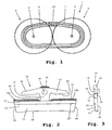
- FIGS 2 and 3 show a transverse element 10.
- a first main body surface of the transverse element 10 is indicated in general by the reference sign 11, whereas a second main body surface of the transverse element 10 is indicated in general by the reference sign 12.
- a circumferential surface 20 is extending between the main body surfaces 11, 12.
- the transverse element 10 comprises successively a basic portion 13, a relatively narrow neck portion 14 and a top portion 15.
- the basic portion 13 is located at the side of the inner circumference of the push belt 6
- the top portion 15 is located at the side of the outer circumference of the push belt 6.
- the basic portion 13 of the transverse element 10 as shown in figure 2 comprises two bearing surfaces 21 which serve for supporting two carriers 7 of the push belt 6. Furthermore, the basic portion 13 comprises two contact surfaces 22.
- a bottom surface 23 is extending between the contact surfaces 22.
- the bearing surfaces 21, the contact surfaces 22, as well as the bottom surface 23 are part of the circumferential surface 20.
- Other parts of the circumferential surface 20 are neck surfaces 24 which are located at the neck portion 14, retaining surfaces 25 which are extending at a bottom side of the top portion 15, and which, as a consequence, are located opposite to the bearing surfaces 21, and top surfaces 26 which are extending at a top side of the top portion 15.
- a space in which the carriers 7 are located is delimited in a radial direction by the bearing surfaces 21 at one side and by the retaining surfaces 25 at another side.
- a recessed portion 16 is arranged, which manifests itself as a hole at the side of the first main body surface 11, and which manifests itself as a projection at the side of the second main body surface 12.
- the hole is depicted by means of a dashed line. In the shown example, a major part of the recessed portion 16 is located at the top portion 15.
- the projection of the recessed portion 16 of the transverse element 10 is at least partially located in the hole of the recessed portion 16 of an adjacent transverse element 10.
- the recessed portions 16 serve to prevent mutual displacement of the adjacent transverse elements 10 in a plane perpendicular to the circumferential direction of the push belt 6.
- a tilting line 17 is defined at the first main body surface 11 of the transverse element 10. In figure 2 , the tilting line 17 is indicated by a dash and dot line. In the shown example, the tilting line 17 is extending along the entire width of the transverse element 10, wherein the tilting line 17 is located at a lightly convexly curved area at the basic portion 13 of the transverse element 10. An important function of the tilting line 17 is guaranteeing mutual contact between two adjacent transverse elements 10 when, during a movement of the push belt 6, said transverse elements 10 are moving over one of the pulleys 4, 5, for example.
- the transverse element 10 may have other features than described above. For instance, it is not at all necessary that the contact areas 18, 19a, 19b are present at the first main body surface 11 of the transverse element 10.
- FIG 4 a chronological overview, as it were, is given of the different steps which are carried out according to the first method in order to realize the transverse element 10.
- FIG 4 an illustration of one of the steps of the first method is depicted, in an enlarged fashion.
- a carrier 30 is shown, which is shaped as a strip of material from which the transverse elements 10 are formed.
- the transverse elements 10 are manufactured of metal.
- the transverse elements 10 are formed in a number of steps, in two rows which are extending in the longitudinal direction of the carrier 30.
- the transverse elements 10 are formed in pairs, wherein the top portions 15 of the transverse elements 10 are directed towards each other, and wherein the basic portions 13 of the transverse elements 10 are located at the side of an edge of the carrier 30. Therefore, the various operations which are performed on the carrier 30 are taking place at opposite sides of a central axis 31 of the carrier 30, and are performed in a mirror-symmetrical fashion.
- the transverse elements 10 in the process of formation are referred to as basic elements 32.
- a first step of the first method according to the invention which is illustrated in a section of figure 4 that is indicated by the letter A, four portions are blanked out of the carrier 30 under the influence of four cutting dies 41. Because of this, the recesses of four basic elements 32, which are delimited by the bearing surfaces 21, the neck surfaces 24 and the retaining surfaces 25, are made in the carrier 30, in a rough form. The recesses in rough form are indicated by the reference numeral 33.
- a second step of the first method according to the invention which is illustrated in a section of figure 4 that is indicated by the letter B, two portions are blanked out of the carrier 30 under the influence of two cutting dies 42.
- a third step of the first method according to the invention which is illustrated in a section of figure 4 that is indicated by the letter C, and which is also illustrated in figure 5 , four portions are cut out of the carrier 30 under the influence of four cutting dies 44, wherein the major part of the top surfaces 26 of two opposite basic portions 32 is formed, with the exception of a top part.
- the top portions 15 having the top surfaces 26 and the retaining surfaces 25 in rough form are almost completely free from the other parts of the carrier 30.
- portions at the edges of the carrier 30 are cut away under the influence of two cutting dies 45, wherein the bottom surfaces 23 of the basic portions 32 are formed.
- a shaping die 46, 47 is pressed on the carrier 30, at very turn on opposite sides of the central axis 31, wherein the two opposite basic elements 32 are covered by the shaping dies 46, 47.
- the shaping dies 46, 47 comprise two die parts 46, 47, including a T-shaped die part 46. Shaping surfaces of the die parts 46, 47 directed towards the basic part 32 are positioned at a different height, whereby a desired relief is realized in the first main body surface 11 of the basic elements 32.
- each of the die parts 46, 47 may be provided with a relief that is suitable to realize a desired relief in the first main body surface 11 of the basic elements 32 under pressure.
- the elevated contact areas 18, 19a, 19b at the first main body surface 11 of the basic elements 32 are realized by an elevated position of the T-shaped die part 46 with respect to the other die part 47, and the tilting line 17 is formed in the first main body surface 11 by a corresponding relief in the shaping surface of at least this other die part 47.
- the recessed portion 16 is formed in the basic elements 32 by exerting local pressure on the first main body surface 11 of the basic elements 32.
- a large part of the contour of the transverse elements 10, namely a continuous whole of contact surface 22, bearing surface 21, neck surface 24 and retaining surface 25, is formed by applying four cutting dies 48.
- the two basic elements 32 are subjected to a treatment that is known as finish cutting. This means that at the position of the surfaces 21, 22, 24, 25 which are to be formed, portions of the edges of the basic elements 32 are cut off.
- Each cutting die 48 serves to form a set of contact surface 22, bearing surface 21, neck surface 24 and retaining surface 25.
- the cutting dies 48 In positioning the cutting dies 48, use is made of the recessed portion 16 that has been realized in the basic elements 32 in the fifth step.
- the cutting dies 48 are connected to a conical centring pin that is inserted into the recessed portion 16. In this way, it is achieved that the position of the part of the contour having the contact surface 22, the retaining surface 21, the neck surface 24 and the retaining surface 25 is accurately adapted to the position of the recessed portion 16. Because of the fact that the said part of the contour is formed at two sides of the basic elements 32 by applying one cutting die 48, a very accurate adaptation of the positions of the respective surfaces 21, 22, 24, 25 between them is also achieved.
- the transverse elements 10 are ready, wherein the top portions 15 of the transverse elements 10 of a pair of transverse elements 10 are connected to each other through a connecting element 37.
- a pair of transverse elements 10 that is located more at the front and a part of the carrier 30 connected thereto is cut loose from this connecting element 37.
- the transverse elements 10 are cut loose from the connecting element 37.
- the seventh and eighth step are illustrated in a section of figure 4 that is indicated by the letter H, which is depicted in an enlarged fashion in figure 8 .
- steps are carried out simultaneously in successive pairs of transverse elements 10 by applying a single cutting die 49, wherein a pair of transverse elements 10 that is located more at the front is situated at a free end of the carrier 30.
- the cutting die 49 is adapted to cut away a part of the carrier 30 that is extending from the connecting element 37 between the pair of transverse elements 10 that is located more behind to the connecting element 37 between the pair of transverse elements 10 that is located more at the front.
- the transverse elements 10 of the pair that is located more at the front become free, and the pair of transverse elements 10 that is located more behind gets situated at the free end of the carrier 30, after which the transverse elements 10 of this pair may be cut loose from the intermediate connecting element 37 by applying the cutting die 49.
- FIG. 9 a chronological overview, as it were, is given of the different steps which are carried out according to the second method in order to realize the transverse element 10.
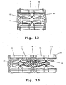
- FIG. 10-13 an illustration of one of the steps of the second method is depicted, in an enlarged fashion.
- the second way in which the method according to the invention may be carried out use is made of a strip-shaped carrier 30 as well, from which the transverse elements 10 are formed in pairs. Also in this case, the various operations which are performed on the carrier 30 are taking place at opposite sides of a central axis 31 of the carrier 30, wherein the operations are performed in a mirror-symmetrical fashion.
- a first step of the second method according to the invention which is illustrated in a section of figure 9 that is indicated by the letter A, two portions are blanked out of the carrier 30 under the influence of two cutting dies 51.
- recesses 61 having straight slots and portions which are shaped like a part of a ring are formed, wherein the slots are extending from the edges of the carrier 30, substantially perpendicular to the longitudinal direction of the carrier 30, wherein the portions which are shaped like a part of a ring are located in the vicinity of the central axis 31 of the carrier 30, and wherein the slots are connected to these portions.
- the recesses 61 which are formed in the first step will hereinafter be referred to as intermediate recesses 61.
- the intermediate recesses 61 are formed with straight slots and portions which are shaped like a part of a ring.
- the latter portions may also be U-shaped or V-shaped.
- a centring hole 34 is blanked in the carrier 30 by applying a round cutting die 43, wherein the centring hole 34 is made at a position between the portions of the intermediate recesses 61 which are formed as a part of a ring, so that the centring hole 34 is located at the central axis 31 of the carrier 30.
- a third step of the second method according to the invention which is illustrated in a section of figure 9 that is indicated by the letter C, and which is also illustrated in figure 10 , four portions are cut out of the carrier 30 under the influence of four cutting dies 44 in an area of the carrier 30 that is located between two centring holes 34, wherein the major part of the top surfaces 26 of two opposite basic portions 32 is formed, with the exception of a top part.
- the four recesses which are formed in the process, are indicated by the reference numeral 62.
- portions at the edges of the carrier 30 are cut away under the influence of two cutting dies 45, wherein the bottom surfaces 23 of the basic portions 32 are formed.
- the result that is obtained after carrying out the third step is depicted in a section of figure 9 that is indicated by the letter D.
- An important difference between the first method and the second method becomes clear when the section D of figure 4 is compared to the section D of figure 9 .
- the first method after carrying out the third step, almost the complete contour of the transverse element 10 is ready, partially in a rough form. In that case, the only place where the contour is not yet formed is the place where the basic element 32 is connected to the carrier 30 through the connecting element 37.
- the second method after the third step, only the bottom surface 23 and the major part of the top surface 26 are ready. Therefore, in the second method, more of the carrier 30 is involved in the steps which are following the third step.
- a fourth step of the second method according to the invention which is illustrated in a section of figure 9 that is indicated by the letter E, and that is also illustrated in figure 11 , is similar to the fourth step of the first method.
- a fifth step of the method according to the invention which is illustrated in a section of figure 9 that is indicated by the letter F, is similar to the fifth step of the first method. It may be so that relatively much material of the carrier 30 is being present around the basic elements 32, but enough material has been removed at strategic places in order to allow for a displacement of material in a direction of the width of the basic elements 32.
- a small widening of the basic portion 13 is allowed for at the position of the intermediate recesses 61, while a small widening of the top portion 15 is allowed for at the position of the top recesses 62.
- a sixth step of the second method according to the invention which is illustrated in a section of figure 9 that is indicated by the letter G, and which is also illustrated in figure 12 , a large part of the contour of the transverse elements 10 is formed by applying four cutting dies 48, namely a continuous whole of contact surface 22, bearing surface 21, neck surface 24 and retaining surface 25. After this step, the complete contour of the transverse elements 10 is obtained, with the exception of a top part of the top surface 26 that is connected to material of the carrier 30.
- the cutting action that is performed is also referred to as full cutting, wherein a portion of the carrier 30 is actually cut loose out of a surrounding area.
- finish cutting that is applied in the first method, wherein the contour of the transverse elements 10 is already present in a rough form, and wherein an edge of this rough form is cut off from the contour.
- finish cutting is that this cutting technique is not well applicable to all types of material which are suitable for the transverse elements 10.
- full cutting there is more freedom in choice of material.
- full cutting there is a higher stiffness, because of more material being present, which helps in increasing the accuracy with which the cutting is performed.
- the transverse elements 10 are ready, wherein the top portions 15 of the transverse elements 10 of a pair of transverse elements 10 are connected to each other through a connecting element 37.
- a seventh and an eighth step as described in relation to the first method, the transverse elements 10 are detached from the carrier 30, after which the transverse elements 10 can be placed in a push belt 6.
- the seventh and eighth step of the second method are illustrated in a section of figure 9 that is indicated by the letter H, which is depicted in an enlarged fashion in figure 13 .
- a difference between the first and the second method relates to the shape of the part of the carrier 30 that is cut loose in the seventh step.
- this part of the carrier 30 comprises strips of material which are extending on opposite sides of the slot of the intermediate recess 61.
- the intermediate recesses 61 do not only have a function in allowing for a small widening of the basic portion 13 of the basic elements 32 during the fourth step.
- Another function of the intermediate recesses 61 is guaranteeing symmetrical conditions at opposite side of an axis of symmetry of the basic elements 32, so that a situation in which there is a higher stiffness at one side of the basic elements 32 than at another side is prevented. Because of this, the accuracy of the various processing steps is increased.
- intermediate recesses 61 Another function of the intermediate recesses 61 is decreasing the stiffness of the strip 30 in a direction perpendicular to the longitudinal direction of the strip 30. Because of this, it is achieved that parts of the strip 30 which are extending between the centring holes 34 are movable with respect to each other, and additionally are capable of following the position that is dictated by the position of the centring pins or the like which are inserted into the centring holes 34.
- a large part of the contour of the transverse element 10, namely the part having the contact surface 22, the bearing surface 21, the neck surface 24 and the retaining surface 25 is cut.
- a rough form has already been cut, and the technique of finish cutting is applied.
- the technique of full cutting is applied.
- a variant of the method according to the invention is also feasible, wherein a considerable part has already been removed between the basic portions 13 of the basic elements 32 at an earlier stage, so that a rough form of the contact surface 22 is obtained.
- the contact surface 22 is cut by finish cutting the rough form, whereas the bearing surface 21, the neck surface 24 and the retaining surface 25 are cut by means of cutting in full material.
- a major advantage of the above-described methods is found in the accuracy with which important surfaces of which the shape and the surface quality are critical are formed.
- a first factor playing a role in this is that the part of the contour having the contacts surface 22, the bearing surface 21, the neck surface 24 and the retaining surface 25 is realized in one cutting movement.
- a second factor playing a role in this is that this part of the contour is formed no earlier than that other parts of the contour have been formed and the first main body surface 11 of the basic element 32 has been shaped under pressure.
- a third factor playing a role in this is that strips of material of the carrier 30 between the centring holes 34 are left intact up to and including the sixth step, which function as tension rods with which stiffness in the longitudinal direction is obtained.
- Surfaces of transverse elements 10 which have been manufactured by applying the method according to the invention have a high accuracy. However, within the framework of the invention, it is not excluded that the transverse elements 10 are subjected to any finishing operation. In case it is desired to leave the transverse elements 10 connected to the carrier 30 for the purpose of one or more finishing operations, the seventh and the eighth step may be omitted, or postponed in any case.
- the transverse elements 10 may remain connected to the carrier 30 at one or more places than at a top part of the top surface 26 until the transverse elements 10 are completely separated from the carrier 30 in a last step.
- the first main body surface 11 of the transverse element 10 has a stepped shape, as shown in figures 2 and 3 , wherein two areas of the main body surface 11 are extending at different levels and are connected to each other through a step 27.
- an area of the main body surface 11 at a bottom part of the basic portion 13 of the transverse element 10 is recessed with respect to another area of the main body surface 11, as a result of which undesired contact between the bottom parts of the basic portions 13 of adjacent transverse elements 10 which are present in a push belt 6, and which, in the push belt 6, are moving over a pulley 4, 5 of a continuously variable transmission 1, is prevented.
- a strip-shaped carrier 30 that has already at least one step is applied, wherein the step is extending in the longitudinal direction of the carrier 30.
- a non-stepped carrier 30 is used, wherein the method according to the invention comprises a step for realizing the desired step 27.
- this step comprises applying a shaping die (not shown), for example a shaping die having at least two die parts of which the shaping surfaces are positioned at different heights, positioning the shaping die with respect to the carrier 30, and exerting pressure on the carrier 30.
- a step of forming a step 27 in the basic elements 32 may for example be carried out between the second step and the third step of the methods which have been described in the above on the basis of figures 4-13 .
- these figures 4-13 relate to a situation in which a stepped carrier 30 is taken as initial material, and therefore, the step 27 is shown in each of these figures.
- the step 27 is formed during carrying out the fourth step of the methods, which is aimed at realizing a desired relief in the first main body surface 11 of the basic elements 32 under pressure.
- the step of realizing the step 27 in the basic elements 32 does not necessarily need to be part of the method according to the invention.
- this step is carried out prior to another manufacturing process of transverse elements 10, for example a process in which fine blanking techniques are applied to blank the transverse elements 10 out of basic material, wherein, besides a cutting member, a supporting member is applied for temporarily supporting a cut-out portion.
- a transverse element 10 that is destined to be part of a push belt 6 for a continuously variable transmission 1 is manufactured of a basic element 32 that comprises a portion of a strip-shaped carrier 30.
- various cutting operations and shaping operations are performed in the basic element 32.
- a first cutting operation is aimed at obtaining a first part of the contour of the transverse element 10.
- Shaping operations are aimed at realizing a desired relief at a main body surface 11, 12 of the transverse element 10, wherein a recessed portion 16 is also realized in the transverse element 10.
- a second cutting operation is aimed at obtaining a second part of the contour of the transverse element 10 that, in any case, comprises the bearing surfaces 21 for supporting carriers 7 of the push belt 6 and the contact surfaces 22 for establishing contact to pulleys 4, 5 of the continuously variable transmission 1. Because of the fact that this second cutting operation is performed no earlier than that the other said operations have been performed, it is achieved that the formation of the bearing surfaces 21 and the contact surfaces 22 takes place with a high accuracy.
Landscapes
- Engineering & Computer Science (AREA)
- General Engineering & Computer Science (AREA)
- Mechanical Engineering (AREA)
- Punching Or Piercing (AREA)
Claims (13)
- Verfahren zur Herstellung eines Querelements (10), das als Teil eines Schubriemens (6) für ein stufenloses Getriebe (1) vorgesehen ist, wobei das Querelement (10) zwei Auflageflächen (21) zum Abstützen von Trägern (7) des Schubriemens (6) und zwei Kontaktflächen (22) zum Herstellen von Kontakt zwischen dem Querelement (10) und Riemenscheiben (4, 5) des stufenlosen Getriebes (1) aufweist, wobei ein Basiselement (32) vorgesehen ist und wobei die folgenden Arbeitsgänge an dem Basiselement (32) verrichtet werden:- Herstellen einer ersten Anzahl von Ausnehmungen, um eine erste Anzahl von Abschnitten einer Kontur des Querelements (10) zu erhalten,- Aufbringen von Druck an verschiedenen Positionen an einer Hauptteilfläche (11, 12) des Basiselements (32), um eine Hauptteilfläche (11, 12) des Querelements (10) zu formen, und- Herstellen einer zweiten Anzahl von Ausnehmungen, um eine zweite Anzahl von Abschnitten der Kontur des Querelements (10) zu erhalten, umfassend die Auflageflächen (21) und die Kontaktflächen (22) des Querelements (10),wobei letzterer Arbeitsgang verrichtet wird, nachdem die anderen Arbeitsgänge verrichtet worden sind.
- Verfahren nach Anspruch 1, wobei das Formen einer Hauptteilfläche (11, 12) des Querelements (10) durch Aufbringen von Druck in zwei Phasen erfolgt, wobei in einer ersten Phase Druck ausgeübt wird, um Material des Basiselements (32) über den Hauptteilflächen (11, 12) zu verlagern, wobei eine vorbestimmte Aussparung in der Hauptteilfläche (11, 12) erzielt wird, und wobei in einer zweiten Phase Druck aufgebracht wird, um einen vertieften Teilbereich (16) in dem Basiselement (32) zu formen, als deren Ergebnis eine Erhebung an einer Hauptteilfläche (11, 12) des Querelements (10) und eine Aussparung an einer anderen Hauptteilfläche (11, 12) des Querelements (10) erhalten wird.
- Verfahren nach Anspruch 2, wobei zum Zweck des Herstellens der zweiten Anzahl von Ausnehmungen Schneidglieder (48) zum Einsatz kommen und wobei Positionen der Schneidglieder (48) bezogen auf das Basiselement (32) an eine Position des vertieften Teilbereichs (16) angepasst werden, der in dem Basiselement (32) ausgebildet ist.
- Verfahren nach Anspruch 3, wobei zum Zweck des Positionierens der Schneidglieder (48) bezogen auf das Basiselement (32) ein mit den Schneidgliedern (48) verbundenes Positionsteil zum Einsatz kommt, das in den vertieften Teilbereich (16) eingeführt wird, der in dem Basiselement (32) ausgebildet ist.
- Verfahren nach einem der Ansprüche 1 bis 4, wobei das Formen einer Hauptteilfläche (11, 12) des Querelements (10) durch Aufbringen von Druck das Herstellen einer Stufe (27) in der Hauptteilfläche (11, 12) umfasst.
- Verfahren nach einem der Ansprüche 1 bis 5, wobei das Herstellen der zweiten Anzahl von Ausnehmungen das Ausschneiden von Teilbereichen des Basiselements (32) beinhaltet, und wobei vor dem Prozess des Ausschneidens der Großteil dieser Teilbereiche von Material umgeben ist.
- Verfahren nach einem der Ansprüche 1 bis 6, wobei das Basiselement (32), aus dem das Querelement (10) hergestellt wird, Teil eines Trägers (30) ist, der mehr als ein Basiselement (32) umfasst.
- Verfahren nach Anspruch 7, wobei das Querelement (10) nach dem Herstellen der zweiten Anzahl von Ausnehmungen letztendlich durch Abtrennen des Basiselements (32) von dem Träger (30) erhalten wird.
- Verfahren nach Anspruch 7 oder 8, wobei nach dem Herstellen der zweiten Anzahl von Ausnehmungen das Basiselement (32) mit dem Träger (30) an einem Ende eines oberen Teilbereichs (15) verbunden wird, in dem mindestens ein Teil des vertieften Teilbereichs (16) angeordnet ist.
- Verfahren nach einem der Ansprüche 7 bis 9, wobei der Träger wie ein Streifen ausgebildet ist, wobei Basiselemente (32), die nacheinander in einer Längsrichtung des Trägers (30) positioniert sind, aufeinander folgenden Arbeitsgängen unterzogen werden.
- Verfahren nach Anspruch 10, wobei die aufeinander folgenden Arbeitsgänge an Basiselementen (32) verrichtet werden, die nacheinander in der Längsrichtung positioniert werden.
- Verfahren nach Anspruch 10 oder 11, wobei in einer Querrichtung der Träger (30) Paare von Basiselementen (32) aufweist, wobei in einer Längsrichtung Materialstreifen (35) des Trägers (30), die sich zwischen den Basiselementen (32) der Paare von Basiselementen (32) erstrecken, unversehrt bleiben bis die Basiselemente (32) von dem Träger (30) abgetrennt werden.
- Verfahren nach Anspruch 12, wobei der Träger (30) an Positionen, die zwischen den Paaren von Basiselementen (32) in einer Längsrichtung angeordnet sind, mit Zentrierbohrungen (34) versehen ist.
Applications Claiming Priority (2)
| Application Number | Priority Date | Filing Date | Title |
|---|---|---|---|
| NL1030702A NL1030702C2 (nl) | 2005-12-19 | 2005-12-19 | Werkwijze voor het vervaardigen van een dwarselement dat bestemd is om deel uit te maken van een duwband voor een continu variabele transmissie. |
| PCT/NL2006/000640 WO2007073159A1 (en) | 2005-12-19 | 2006-12-18 | Method for manufacturing a transverse element that is destined to be part of a push belt for a continuously variable transmission |
Publications (2)
| Publication Number | Publication Date |
|---|---|
| EP1968760A1 EP1968760A1 (de) | 2008-09-17 |
| EP1968760B1 true EP1968760B1 (de) | 2011-11-23 |
Family
ID=36579437
Family Applications (1)
| Application Number | Title | Priority Date | Filing Date |
|---|---|---|---|
| EP06835663A Not-in-force EP1968760B1 (de) | 2005-12-19 | 2006-12-18 | Verfahren zur herstellung eines querelements, das teil eines schubgliederbands für ein stufenloses getriebe bilden soll |
Country Status (6)
| Country | Link |
|---|---|
| EP (1) | EP1968760B1 (de) |
| JP (1) | JP5350801B2 (de) |
| CN (1) | CN101340989B (de) |
| AT (1) | ATE534478T1 (de) |
| NL (1) | NL1030702C2 (de) |
| WO (1) | WO2007073159A1 (de) |
Families Citing this family (10)
| Publication number | Priority date | Publication date | Assignee | Title |
|---|---|---|---|---|
| NL1036318C2 (en) * | 2008-12-16 | 2010-06-17 | Bosch Gmbh Robert | Method for forming defined contact zones on a surface of an element which is destined to be part of a push belt for a continuously variable transmission. |
| EP2425907B1 (de) * | 2009-04-27 | 2015-02-11 | Honda Motor Co., Ltd. | Verfahren zur herstellung eines elements für den riemen eines stufenlosen getriebes |
| NL1037273C2 (en) * | 2009-09-11 | 2011-03-14 | Bosch Gmbh Robert | Method for manufacturing a transverse element which is destined to be part of a push belt for a continuously variable transmission. |
| NL1039275C2 (en) | 2011-12-30 | 2013-07-03 | Bosch Gmbh Robert | Method for manufacturing a transverse element which is destined to be part of a drive belt for a continuously variable transmission. |
| NL1039973C2 (en) | 2012-12-24 | 2014-06-25 | Bosch Gmbh Robert | Drive belt with a carrier ring and transverse segments. |
| NL1042209B1 (en) * | 2016-12-30 | 2018-07-23 | Bosch Gmbh Robert | Method for manufacturing a transverse segment for a drive belt for a continuously variable transmission |
| NL1042210B1 (en) * | 2016-12-30 | 2018-07-23 | Bosch Gmbh Robert | Method for manufacturing a transverse segment for a drive belt for a continuously variable transmission |
| NL1042202B1 (en) * | 2016-12-30 | 2018-07-23 | Bosch Gmbh Robert | Method for manufacturing a transverse segment for a drive belt for a continuously variable transmission and a transverse segment thus manufactured |
| CN108799410B (zh) | 2017-04-28 | 2020-08-18 | 本田技研工业株式会社 | 无级变速器用金属元件的制造方法 |
| CN114651140A (zh) * | 2019-11-22 | 2022-06-21 | 罗伯特·博世有限公司 | 用于制造用于无级变速器的推带的横向段的方法和由此获得的横向段 |
Family Cites Families (10)
| Publication number | Priority date | Publication date | Assignee | Title |
|---|---|---|---|---|
| NL8700156A (nl) * | 1987-01-23 | 1988-08-16 | Doornes Transmissie Bv | Drijfriem, dwarselement voor een drijfriem en werkwijze en inrichting voor de vervaardiging daarvan. |
| DE60102958T2 (de) * | 2000-02-21 | 2005-04-07 | Honda Giken Kogyo K.K. | Verfahren und Vorrichtung zum Stanzen von Teilen von einem Riemen für stufenlos regelbares Getriebe |
| JP3703678B2 (ja) * | 2000-03-06 | 2005-10-05 | 本田技研工業株式会社 | 無段変速機用ベルトのエレメントの打抜き加工方法 |
| DE60125356T2 (de) * | 2000-04-17 | 2007-04-19 | Honda Giken Kogyo K.K. | Herstellungsverfahren von keilstück einer mit metallriemen stufenlos regelbaren getriebes und metallform für das keilstück |
| JP3676192B2 (ja) * | 2000-05-26 | 2005-07-27 | 本田技研工業株式会社 | 無段変速機用ベルトのエレメントの打抜き加工方法 |
| NL1019639C2 (nl) * | 2001-12-21 | 2003-06-24 | Werkwijze voor het vormen van een schakel voor een duwband voor een continu variabele transmissie. | |
| DE60116795T2 (de) * | 2001-12-24 | 2006-08-17 | Van Doorne's Transmissie B.V. | Werkstück,schubtreibriemen und verfahren und werkzeug dafür |
| JP3827005B2 (ja) * | 2002-06-12 | 2006-09-27 | アイダエンジニアリング株式会社 | 無段変速機ベルトのエレメント製造方法 |
| JP4315672B2 (ja) * | 2002-11-28 | 2009-08-19 | 株式会社三井ハイテック | 無段変速機用ベルトのエレメントの製造方法 |
| NL1024957C2 (nl) * | 2003-12-05 | 2005-06-07 | Bosch Gmbh Robert | Fijnstansinrichting. |
-
2005
- 2005-12-19 NL NL1030702A patent/NL1030702C2/nl not_active IP Right Cessation
-
2006
- 2006-12-18 WO PCT/NL2006/000640 patent/WO2007073159A1/en not_active Ceased
- 2006-12-18 EP EP06835663A patent/EP1968760B1/de not_active Not-in-force
- 2006-12-18 CN CN2006800477870A patent/CN101340989B/zh not_active Expired - Fee Related
- 2006-12-18 AT AT06835663T patent/ATE534478T1/de active
- 2006-12-18 JP JP2008545518A patent/JP5350801B2/ja not_active Expired - Fee Related
Also Published As
| Publication number | Publication date |
|---|---|
| CN101340989B (zh) | 2012-06-27 |
| ATE534478T1 (de) | 2011-12-15 |
| WO2007073159A1 (en) | 2007-06-28 |
| JP5350801B2 (ja) | 2013-11-27 |
| JP2009520166A (ja) | 2009-05-21 |
| CN101340989A (zh) | 2009-01-07 |
| EP1968760A1 (de) | 2008-09-17 |
| NL1030702C2 (nl) | 2007-06-20 |
Similar Documents
| Publication | Publication Date | Title |
|---|---|---|
| US8100797B2 (en) | Method for forming a tilting zone on a transverse element for a push belt for a continuously variable transmission | |
| EP3063432B1 (de) | Verfahren zur herstellung eines transversalen segments für ein schubband für ein stufenloses getriebe und so erhaltenes transversales segment | |
| EP1968760A1 (de) | Verfahren zur herstellung eines querelements, das teil eines schubgliederbands für ein stufenloses getriebe bilden soll | |
| JP6602768B2 (ja) | ファインブランキング装置 | |
| US20090158808A1 (en) | Method for Manufacturing Ring-Shaped Member | |
| US4621515A (en) | Method and apparatus for making circlips | |
| US6289589B1 (en) | Method and device for produced flanged bearings | |
| JP6203193B2 (ja) | 無段変速機用の駆動ベルトの一部としての横方向エレメントの製造法 | |
| JP2004174585A (ja) | 無段変速機用ベルトのエレメントの製造方法 | |
| CN108266495B (zh) | 用于制造用于无级变速器的传动带的横向段的方法 | |
| JP2007516084A (ja) | 精密打抜装置 | |
| JP5013873B2 (ja) | 無段変速機用のプッシュベルトのためのトランスバース(横断)素子のブランキング(打ち抜き)処理におけるバリの形成防止 | |
| CN110139997B (zh) | 制造用于无级变速器的传动带的横向段的方法 | |
| CN108266494B (zh) | 无级变速器的传动带的横向段的制造方法及制造的横向段 | |
| JP5401472B2 (ja) | 無段変速機用のプッシュベルトに用いられる横断素子を打ち抜くためのブランキングアセンブリ | |
| CN102483128B (zh) | 制造预定成为无级变速器的推送带的一部分的横向元件的方法 | |
| JP4839223B2 (ja) | 少なくとも2つの型部材を有する分割型 | |
| CN114651140A (zh) | 用于制造用于无级变速器的推带的横向段的方法和由此获得的横向段 | |
| JP6129205B2 (ja) | 連続可変トランスミッションの駆動ベルトに使用される横断エレメントを打ち抜くための分割型ブランキング部材 | |
| JP2004136339A (ja) | 無段変速機用伝動ベルトのエレメントの製造方法 | |
| EP2797706A1 (de) | Verfahren zur herstellung einer neigezone auf einem querelement für einen schubriemen für ein stufenlos regelbares getriebe |
Legal Events
| Date | Code | Title | Description |
|---|---|---|---|
| PUAI | Public reference made under article 153(3) epc to a published international application that has entered the european phase |
Free format text: ORIGINAL CODE: 0009012 |
|
| 17P | Request for examination filed |
Effective date: 20080717 |
|
| AK | Designated contracting states |
Kind code of ref document: A1 Designated state(s): AT BE BG CH CY CZ DE DK EE ES FI FR GB GR HU IE IS IT LI LT LU LV MC NL PL PT RO SE SI SK TR |
|
| 17Q | First examination report despatched |
Effective date: 20101019 |
|
| RIN1 | Information on inventor provided before grant (corrected) |
Inventor name: PRINSEN, LUCAS, HENDRICUS, ROBERTUS, MARIA |
|
| GRAP | Despatch of communication of intention to grant a patent |
Free format text: ORIGINAL CODE: EPIDOSNIGR1 |
|
| GRAS | Grant fee paid |
Free format text: ORIGINAL CODE: EPIDOSNIGR3 |
|
| GRAA | (expected) grant |
Free format text: ORIGINAL CODE: 0009210 |
|
| DAX | Request for extension of the european patent (deleted) | ||
| AK | Designated contracting states |
Kind code of ref document: B1 Designated state(s): AT BE BG CH CY CZ DE DK EE ES FI FR GB GR HU IE IS IT LI LT LU LV MC NL PL PT RO SE SI SK TR |
|
| REG | Reference to a national code |
Ref country code: GB Ref legal event code: FG4D |
|
| REG | Reference to a national code |
Ref country code: CH Ref legal event code: EP |
|
| REG | Reference to a national code |
Ref country code: IE Ref legal event code: FG4D |
|
| REG | Reference to a national code |
Ref country code: NL Ref legal event code: T3 |
|
| REG | Reference to a national code |
Ref country code: DE Ref legal event code: R096 Ref document number: 602006026069 Country of ref document: DE Effective date: 20120308 |
|
| LTIE | Lt: invalidation of european patent or patent extension |
Effective date: 20111123 |
|
| PG25 | Lapsed in a contracting state [announced via postgrant information from national office to epo] |
Ref country code: IS Free format text: LAPSE BECAUSE OF FAILURE TO SUBMIT A TRANSLATION OF THE DESCRIPTION OR TO PAY THE FEE WITHIN THE PRESCRIBED TIME-LIMIT Effective date: 20120323 Ref country code: LT Free format text: LAPSE BECAUSE OF FAILURE TO SUBMIT A TRANSLATION OF THE DESCRIPTION OR TO PAY THE FEE WITHIN THE PRESCRIBED TIME-LIMIT Effective date: 20111123 |
|
| PG25 | Lapsed in a contracting state [announced via postgrant information from national office to epo] |
Ref country code: SI Free format text: LAPSE BECAUSE OF FAILURE TO SUBMIT A TRANSLATION OF THE DESCRIPTION OR TO PAY THE FEE WITHIN THE PRESCRIBED TIME-LIMIT Effective date: 20111123 Ref country code: GR Free format text: LAPSE BECAUSE OF FAILURE TO SUBMIT A TRANSLATION OF THE DESCRIPTION OR TO PAY THE FEE WITHIN THE PRESCRIBED TIME-LIMIT Effective date: 20120224 Ref country code: LV Free format text: LAPSE BECAUSE OF FAILURE TO SUBMIT A TRANSLATION OF THE DESCRIPTION OR TO PAY THE FEE WITHIN THE PRESCRIBED TIME-LIMIT Effective date: 20111123 Ref country code: SE Free format text: LAPSE BECAUSE OF FAILURE TO SUBMIT A TRANSLATION OF THE DESCRIPTION OR TO PAY THE FEE WITHIN THE PRESCRIBED TIME-LIMIT Effective date: 20111123 Ref country code: PT Free format text: LAPSE BECAUSE OF FAILURE TO SUBMIT A TRANSLATION OF THE DESCRIPTION OR TO PAY THE FEE WITHIN THE PRESCRIBED TIME-LIMIT Effective date: 20120323 Ref country code: BE Free format text: LAPSE BECAUSE OF FAILURE TO SUBMIT A TRANSLATION OF THE DESCRIPTION OR TO PAY THE FEE WITHIN THE PRESCRIBED TIME-LIMIT Effective date: 20111123 |
|
| PG25 | Lapsed in a contracting state [announced via postgrant information from national office to epo] |
Ref country code: CY Free format text: LAPSE BECAUSE OF FAILURE TO SUBMIT A TRANSLATION OF THE DESCRIPTION OR TO PAY THE FEE WITHIN THE PRESCRIBED TIME-LIMIT Effective date: 20111123 |
|
| PG25 | Lapsed in a contracting state [announced via postgrant information from national office to epo] |
Ref country code: CZ Free format text: LAPSE BECAUSE OF FAILURE TO SUBMIT A TRANSLATION OF THE DESCRIPTION OR TO PAY THE FEE WITHIN THE PRESCRIBED TIME-LIMIT Effective date: 20111123 Ref country code: SK Free format text: LAPSE BECAUSE OF FAILURE TO SUBMIT A TRANSLATION OF THE DESCRIPTION OR TO PAY THE FEE WITHIN THE PRESCRIBED TIME-LIMIT Effective date: 20111123 Ref country code: MC Free format text: LAPSE BECAUSE OF NON-PAYMENT OF DUE FEES Effective date: 20111231 Ref country code: DK Free format text: LAPSE BECAUSE OF FAILURE TO SUBMIT A TRANSLATION OF THE DESCRIPTION OR TO PAY THE FEE WITHIN THE PRESCRIBED TIME-LIMIT Effective date: 20111123 Ref country code: BG Free format text: LAPSE BECAUSE OF FAILURE TO SUBMIT A TRANSLATION OF THE DESCRIPTION OR TO PAY THE FEE WITHIN THE PRESCRIBED TIME-LIMIT Effective date: 20120223 Ref country code: EE Free format text: LAPSE BECAUSE OF FAILURE TO SUBMIT A TRANSLATION OF THE DESCRIPTION OR TO PAY THE FEE WITHIN THE PRESCRIBED TIME-LIMIT Effective date: 20111123 |
|
| REG | Reference to a national code |
Ref country code: CH Ref legal event code: PL |
|
| PG25 | Lapsed in a contracting state [announced via postgrant information from national office to epo] |
Ref country code: IT Free format text: LAPSE BECAUSE OF FAILURE TO SUBMIT A TRANSLATION OF THE DESCRIPTION OR TO PAY THE FEE WITHIN THE PRESCRIBED TIME-LIMIT Effective date: 20111123 Ref country code: RO Free format text: LAPSE BECAUSE OF FAILURE TO SUBMIT A TRANSLATION OF THE DESCRIPTION OR TO PAY THE FEE WITHIN THE PRESCRIBED TIME-LIMIT Effective date: 20111123 Ref country code: PL Free format text: LAPSE BECAUSE OF FAILURE TO SUBMIT A TRANSLATION OF THE DESCRIPTION OR TO PAY THE FEE WITHIN THE PRESCRIBED TIME-LIMIT Effective date: 20111123 |
|
| REG | Reference to a national code |
Ref country code: AT Ref legal event code: MK05 Ref document number: 534478 Country of ref document: AT Kind code of ref document: T Effective date: 20111123 |
|
| REG | Reference to a national code |
Ref country code: IE Ref legal event code: MM4A |
|
| PLBE | No opposition filed within time limit |
Free format text: ORIGINAL CODE: 0009261 |
|
| STAA | Information on the status of an ep patent application or granted ep patent |
Free format text: STATUS: NO OPPOSITION FILED WITHIN TIME LIMIT |
|
| 26N | No opposition filed |
Effective date: 20120824 |
|
| PG25 | Lapsed in a contracting state [announced via postgrant information from national office to epo] |
Ref country code: IE Free format text: LAPSE BECAUSE OF NON-PAYMENT OF DUE FEES Effective date: 20111218 Ref country code: CH Free format text: LAPSE BECAUSE OF NON-PAYMENT OF DUE FEES Effective date: 20111231 Ref country code: LI Free format text: LAPSE BECAUSE OF NON-PAYMENT OF DUE FEES Effective date: 20111231 |
|
| REG | Reference to a national code |
Ref country code: DE Ref legal event code: R097 Ref document number: 602006026069 Country of ref document: DE Effective date: 20120824 |
|
| PG25 | Lapsed in a contracting state [announced via postgrant information from national office to epo] |
Ref country code: AT Free format text: LAPSE BECAUSE OF FAILURE TO SUBMIT A TRANSLATION OF THE DESCRIPTION OR TO PAY THE FEE WITHIN THE PRESCRIBED TIME-LIMIT Effective date: 20111123 |
|
| PG25 | Lapsed in a contracting state [announced via postgrant information from national office to epo] |
Ref country code: ES Free format text: LAPSE BECAUSE OF FAILURE TO SUBMIT A TRANSLATION OF THE DESCRIPTION OR TO PAY THE FEE WITHIN THE PRESCRIBED TIME-LIMIT Effective date: 20120305 |
|
| PG25 | Lapsed in a contracting state [announced via postgrant information from national office to epo] |
Ref country code: LU Free format text: LAPSE BECAUSE OF NON-PAYMENT OF DUE FEES Effective date: 20111218 |
|
| PG25 | Lapsed in a contracting state [announced via postgrant information from national office to epo] |
Ref country code: FI Free format text: LAPSE BECAUSE OF FAILURE TO SUBMIT A TRANSLATION OF THE DESCRIPTION OR TO PAY THE FEE WITHIN THE PRESCRIBED TIME-LIMIT Effective date: 20111123 |
|
| PG25 | Lapsed in a contracting state [announced via postgrant information from national office to epo] |
Ref country code: TR Free format text: LAPSE BECAUSE OF FAILURE TO SUBMIT A TRANSLATION OF THE DESCRIPTION OR TO PAY THE FEE WITHIN THE PRESCRIBED TIME-LIMIT Effective date: 20111123 |
|
| PG25 | Lapsed in a contracting state [announced via postgrant information from national office to epo] |
Ref country code: HU Free format text: LAPSE BECAUSE OF FAILURE TO SUBMIT A TRANSLATION OF THE DESCRIPTION OR TO PAY THE FEE WITHIN THE PRESCRIBED TIME-LIMIT Effective date: 20111123 |
|
| REG | Reference to a national code |
Ref country code: FR Ref legal event code: PLFP Year of fee payment: 10 |
|
| PGFP | Annual fee paid to national office [announced via postgrant information from national office to epo] |
Ref country code: GB Payment date: 20151221 Year of fee payment: 10 |
|
| PGFP | Annual fee paid to national office [announced via postgrant information from national office to epo] |
Ref country code: FR Payment date: 20151218 Year of fee payment: 10 |
|
| GBPC | Gb: european patent ceased through non-payment of renewal fee |
Effective date: 20161218 |
|
| REG | Reference to a national code |
Ref country code: FR Ref legal event code: ST Effective date: 20170831 |
|
| PG25 | Lapsed in a contracting state [announced via postgrant information from national office to epo] |
Ref country code: FR Free format text: LAPSE BECAUSE OF NON-PAYMENT OF DUE FEES Effective date: 20170102 |
|
| PG25 | Lapsed in a contracting state [announced via postgrant information from national office to epo] |
Ref country code: GB Free format text: LAPSE BECAUSE OF NON-PAYMENT OF DUE FEES Effective date: 20161218 |
|
| PGFP | Annual fee paid to national office [announced via postgrant information from national office to epo] |
Ref country code: NL Payment date: 20201217 Year of fee payment: 15 |
|
| PGFP | Annual fee paid to national office [announced via postgrant information from national office to epo] |
Ref country code: DE Payment date: 20220224 Year of fee payment: 16 |
|
| REG | Reference to a national code |
Ref country code: NL Ref legal event code: MM Effective date: 20220101 |
|
| PG25 | Lapsed in a contracting state [announced via postgrant information from national office to epo] |
Ref country code: NL Free format text: LAPSE BECAUSE OF NON-PAYMENT OF DUE FEES Effective date: 20220101 |
|
| REG | Reference to a national code |
Ref country code: DE Ref legal event code: R119 Ref document number: 602006026069 Country of ref document: DE |
|
| PG25 | Lapsed in a contracting state [announced via postgrant information from national office to epo] |
Ref country code: DE Free format text: LAPSE BECAUSE OF NON-PAYMENT OF DUE FEES Effective date: 20230701 |