EP1968877B1 - Bandabgabevorrichtung mit abdeckung - Google Patents
Bandabgabevorrichtung mit abdeckung Download PDFInfo
- Publication number
- EP1968877B1 EP1968877B1 EP06841045A EP06841045A EP1968877B1 EP 1968877 B1 EP1968877 B1 EP 1968877B1 EP 06841045 A EP06841045 A EP 06841045A EP 06841045 A EP06841045 A EP 06841045A EP 1968877 B1 EP1968877 B1 EP 1968877B1
- Authority
- EP
- European Patent Office
- Prior art keywords
- hand
- held device
- cover
- tip
- neck portion
- Prior art date
- Legal status (The legal status is an assumption and is not a legal conclusion. Google has not performed a legal analysis and makes no representation as to the accuracy of the status listed.)
- Active
Links
Images
Classifications
-
- B—PERFORMING OPERATIONS; TRANSPORTING
- B65—CONVEYING; PACKING; STORING; HANDLING THIN OR FILAMENTARY MATERIAL
- B65H—HANDLING THIN OR FILAMENTARY MATERIAL, e.g. SHEETS, WEBS, CABLES
- B65H37/00—Article or web delivery apparatus incorporating devices for performing specified auxiliary operations
- B65H37/002—Web delivery apparatus, the web serving as support for articles, material or another web
- B65H37/005—Hand-held apparatus
- B65H37/007—Applicators for applying coatings, e.g. correction, colour or adhesive coatings
-
- Y—GENERAL TAGGING OF NEW TECHNOLOGICAL DEVELOPMENTS; GENERAL TAGGING OF CROSS-SECTIONAL TECHNOLOGIES SPANNING OVER SEVERAL SECTIONS OF THE IPC; TECHNICAL SUBJECTS COVERED BY FORMER USPC CROSS-REFERENCE ART COLLECTIONS [XRACs] AND DIGESTS
- Y10—TECHNICAL SUBJECTS COVERED BY FORMER USPC
- Y10T—TECHNICAL SUBJECTS COVERED BY FORMER US CLASSIFICATION
- Y10T156/00—Adhesive bonding and miscellaneous chemical manufacture
- Y10T156/17—Surface bonding means and/or assemblymeans with work feeding or handling means
- Y10T156/1702—For plural parts or plural areas of single part
- Y10T156/1705—Lamina transferred to base from adhered flexible web or sheet type carrier
-
- Y—GENERAL TAGGING OF NEW TECHNOLOGICAL DEVELOPMENTS; GENERAL TAGGING OF CROSS-SECTIONAL TECHNOLOGIES SPANNING OVER SEVERAL SECTIONS OF THE IPC; TECHNICAL SUBJECTS COVERED BY FORMER USPC CROSS-REFERENCE ART COLLECTIONS [XRACs] AND DIGESTS
- Y10—TECHNICAL SUBJECTS COVERED BY FORMER USPC
- Y10T—TECHNICAL SUBJECTS COVERED BY FORMER US CLASSIFICATION
- Y10T156/00—Adhesive bonding and miscellaneous chemical manufacture
- Y10T156/17—Surface bonding means and/or assemblymeans with work feeding or handling means
- Y10T156/1788—Work traversing type and/or means applying work to wall or static structure
- Y10T156/1795—Implement carried web supply
-
- Y—GENERAL TAGGING OF NEW TECHNOLOGICAL DEVELOPMENTS; GENERAL TAGGING OF CROSS-SECTIONAL TECHNOLOGIES SPANNING OVER SEVERAL SECTIONS OF THE IPC; TECHNICAL SUBJECTS COVERED BY FORMER USPC CROSS-REFERENCE ART COLLECTIONS [XRACs] AND DIGESTS
- Y10—TECHNICAL SUBJECTS COVERED BY FORMER USPC
- Y10T—TECHNICAL SUBJECTS COVERED BY FORMER US CLASSIFICATION
- Y10T156/00—Adhesive bonding and miscellaneous chemical manufacture
- Y10T156/18—Surface bonding means and/or assembly means with handle or handgrip
Definitions
- the present invention relates to a hand-held device for transferring a film of adhesive, covering or coloured material from a backing tape onto a substrate according to the preamble of claim 1.
- correction tape applicators or applicators for adhesive tape or the like are known.
- these applicators comprise a housing and a tip of an application member protruding from the housing, whereby correction tape of the like is guided around this tip. Since correction tape or any other tape used for these type of applicators is very sensitive and the tip is always exposed to the ambience and, thus, to outside influences, it is very likely that the tape is injured or even ruptured, when the applicator is not in use and stored somewhere. Once such a tape ruptures, the entire applicator has to be thrown away. However, there exist some solutions to protect the tape from outside influences, when the applicator is not used.
- a cap can be provided, which fits on the housing and which is put on the applicator after use.
- Using such a cap for protection has the disadvantage that it can easily get lost, and then the tip with the tape thereon is unprotected again.
- the applicator is enlarged in size, when a cap is put on the housing, thus, rendering it inconvenient to store.
- the present invention is based on the object to provide a hand-held device for transferring a film of adhesive, covering or coloured material from a backing tape onto a substrate, according to which the application member is reliably protected, when the device is not used, and which is easy to use for a user.
- a hand-held device for transferring a film of adhesive, covering or colored material from a backing tape onto a substrate
- a hand-held device for transferring a film of adhesive, covering or colored material from a backing tape onto a substrate
- the housing is provided with a tip opening, through which a tip of an application member protrudes.
- a cover is provided, the cover being moveable on the neck portion from a first position in which the tip of the application member is uncovered to a second position in which the tip of the application member is covered.
- the cover is arranged radially outside a neck portion of the housing.
- the cover is transferred between the first and the second position by rotating it relative to the housing.
- the cover can e.g. be mounted directly or indirectly on the housing such that it spirals between the first and the second position.
- the tip itself is not rotated when rotating the cover, but fixed in rotation vis-à-vis the housing.
- the cover can comprises a first member adapted to spirally move on the outer surface of the neck portion and a second member connected to the fist member adapted to cover the tip of the application member in the second position.
- the cover stays on the housing, even when the hand-held device is used, so that the cover which is intended to protect the tip, when the hand-held device is not in use, cannot get lost.
- the protection of the tip is achieved in a very easy to handle manner in that the cover is moved from a first position in which the tip is uncovered to a second position in which the tip totally disappears inside a cavity formed by the cover, and, thus, is protected against outside influences.
- the cover moves spirally on the outer surface of the neck portion, facilitating the handling for a user, who without any effort can grip the cover between his thumb and the index finger of one hand and move the cover by twisting it.
- To carry out the twisting motion in the manner described above is much easier for a user than it would be the case, if, e.g., a linear movement would have to be carried out to move the cover in a position to protect the tip.
- the cover smoothly slides on the surface of the cylindrical portion of the neck, whereby the spiral movement is guided by the two guiding members provided inside the first member of the cover.
- the outer circumference of the cylindrical portion of the first member is corrugated or provided with ribs or grip ribs, respectively.
- a user whose finger tip and thumb tip rests on the outer circumference of the cylindrical portion of the cover to twist it in either direction for covering or for uncovering the tip of the application member, will not slide off the cover surface with his finger tips, when performing the twisting motion.
- the cover itself will not slide off the cylindrical neck portion of the hand-held device, since preferably at least one stop pin is provided on the neck portion, projecting from its circumference and restricting the spiral movement so that the cover cannot slip off the neck portion.
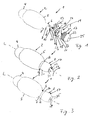
- Fig. 1 shows the hand-held device 1 according to the present invention.
- the housing 2 and the cover 3 are illustrated separately in an exploded view.
- the housing 2 itself has three differently shaped portions: a rear portion 4 having a hemispherical shape, an intermediate portion or main body 5 having a rounded long-stretched or terete, shape, and a neck portion 6 provided at a front end of the hand-held device 1.
- the neck portion 6, moreover, is made up of two differently shaped portions: a cylindrical portion 7 adjacent to the main body 5 and a tapering portion 8, forming the outermost part of the front end of the housing 2.
- a stop pin 9 Projecting from the surface of the cylindrical portion 7 positioned immediately before the transition from the cylindrical portion 7 to the tapering portion 8, there is provided a stop pin 9, against which the cover 3 will abut, when being twisted by a user, and, thus, will not come off the neck portion 6 of the housing 2.
- the tapering portion 8 only has a very slight taper and at the very front end of the tapering portion 8, there is provided a tip opening 10, through which the tip 11 of an application member 12 protrudes.
- a correction tape 13 being composed of a backing tape on the surface of which a film of covering material is applied is directed from the cavity formed inside the housing 2 to the application member 12, around an application edge 14 and back into the housing 2 again.
- the tip 11 has two opposite guiding wings 15, which extend on both sides therefrom substantially perpendicular to form a wall on both sides of the tip 11 such that the correction tape 13 cannot slip off, when the application edge 14 is moved on the surface of a substrate as, e.g., a sheet of paper.
- a recess 20 is formed in the tapering portion 8 of the neck portion 6. The recess 20 extends from the very front end of the tapering portion 8, where also the tip opening 10 is provided, towards the cylindrical portion 7. The recess 20 is arranged directly above the correction tape 13.
- a driving mechanism (not shown) is provided inside the housing 2 or, in particular, in the cavity formed by the housing 2, for supplying the correction tape 13 to the application member 12 and for taking up the used tape.
- the driving mechanism can be of any type, as long as the tape 13 is automatically supplied and taken up, when using the hand-held device 1 in that the application edge 14 is moved on a substrate.
- the cover 3 is illustrated in Fig 1 , as already mentioned above.
- the cover 3 comprises two main components: a lower cam or first member 16 and an upper cam or second member 17.
- the first member 16 in an assembled state of the hand-held device 1, is seated on the neck portion 6 of the housing 2.
- the second member 17 is fixedly connected to the first member 16, when the hand-held device 1 is assembled.
- the first member 16 has a ring-shaped collar 18, the inner diameter of which is slightly larger than the outer diameter of the neck portion 6, so that it fits thereon relatively tight, but however, still has some positive allowance such that the cover 3 can be moved on the neck portion 6.
- Two guiding member 19 are arranged on the inner circumference of the ring-shaped collar 18, substantially opposite to each other.
- Each guiding member 19 is formed with a trailing edge 26, which verges into a steep rising edge 27. Due to this configuration which, moreover, in an assembled state of the hand-held device 1, contacts the outer surface of the cylindrical portion 7 of the neck portion 6 and slides thereon, a spiral movement of the cover 3 on the outer surface of the cylindrical portion 7 is enabled and guided or controlled, respectively, when a user twists the cover 3.
- the cover 3 thus is arranged radially outside the neck portion 6. This has the advantage that essentially the entirety of the cover 3 can be easily gripped in order to be manipulated by the fingers of a user. Preferably the cover is entirely exposed to the outside.
- a further advantage of this arrangement of the cover 3 outside the neck portion 6 is that thus there is more space available inside the neck portion 6. This is of importance e.g. in order to provide for a clearing between the neck portion 6 and the tip in order to allow a flexible (swinging) movement of the tip.
- the screwing mechanism between the cover and the neck portion can comprise a radially acting guiding curve, i.e. one element of the screwing mechanism is arranged radially inside the cover. This can lead to a reduction of the length of the screwing mechanism when compared to a linearly arranged mechanism as it is known e.g. from JP 2005001850 .
- the screwing mechanism according to the invention is preferably arranged radially inside the cover and not at the rear end as it is known e.g. from JP 2005001850 .
- the second member 17 of the cover 3 will now be described.
- the second member 17 substantially corresponds to the shape of the neck portion 6 of the housing 2, but, however, has slightly larger diameters such that it still fits and also can be moved on the neck portion 6.
- the second member 17 also has a cylindrical portion 21, the inner diameter of which is just slightly larger than the outer diameter of the cylindrical portion 7 of the neck portion 6, and a tapering portion 22, the inner diameter of which is just slightly larger than the outer diameter of the tapering portion 8 of the neck portion 6.
- the surface of outer circumference of the cylindrical portion 21 of the second member 17 is corrugated such that grip ribs 23 are formed thereon, to prevent the finger tip and/or thumb tip of a user, who holds the hand-held device 1 in his fingers, to slip off the cover 3, when he twists the cover 3 to cover or uncover, respectively, the application member 12.
- the grip ribs 23 are provided over the entire surface of the cylindrical portion 21.
- they are only provided partially, e.g., just at two positions, where the user should place his finger tips or lengthwise, just covering a portion of the cylindrical portion 21, but still being provided around the entire circumference.
- the second member 17 has a first opening 22, which is adapted and sized to be slid over the first member 16 and a second opening 25, through which the tip 11 of the application member 12 protrudes, when the hand-held device 1 is being used.
- Fig. 2 shows a perspective view of the hand-held device 1 according to the present invention, the cover being in the first position
- Fig. 3 shows a perspective view of the hand-held device according to the present invention, the cover being in the second position.
- the cover 3 of the hand-held device 1 is in the first position, in which the tip 11 of the application member 12 is uncovered, so that the hand-held device 1 is ready for use.
- the tip 11 of the application member 12 protrudes through the second opening 25 of the cover 3.
- the cover 3 is in a retracted position here, since the collar 18 of the first member 16 abuts against the main body 5 of the housing 2 and the neck portion 6 of the housing 2 is totally overlapped by the cover 3, so that it cannot be seen from the outside.
- the cover 3 moves along the longitudinal axis L of the hand-held device 1 spirally around the outer circumference of the cylindrical portion 7 of the neck portion 6, on the surface of which the cover 3 slides.
- the stop pin 9 prevents any further movements such that the cover could slip off the neck portion 6 of the housing 2.
- the hand-held device 1 In this position, which also is an extended position of the cover 3, the hand-held device 1 can be carried along or stored, without any risk that the correction tape 13 gets injured or ruptured. Moreover, in this extended position, a part of the cylindrical portion 7 of the neck portion 6 is uncovered and, thus, visible here.
- the cover 3 To turn the cover 3 back to the first position, if a user wishes to use the hand-held device 1, it just has to be twisted into the opposite direction (as shown by the respective arrows in Fig. 2 and Fig. 3 ), whereas this movement is automatically stopped when the collar 18 abuts against the main body 5 of the housing 2.
- a reliable protection of the tip 11 carrying the correction tape 13 or the like is achieved by a very simple mechanism, which is very easy to handle for a user.
Landscapes
- Adhesive Tape Dispensing Devices (AREA)
- Closures For Containers (AREA)
- Telephone Set Structure (AREA)
Claims (20)
- In der Hand haltbares Gerät (1) zum Übertragen eines Films aus Klebe-, Abdeck- oder farbigem Material von einem Trägerband (13) auf ein Substrat, das aufweist ein Gehäuse (2), das mit einer Spitzenöffnung (10) versehen ist, durch die eine Spitze (11) eines Auftragungselements (12) hervorsteht,
wobei eine Abdeckung (3) vorgesehen ist,
wobei die Abdeckung (3) relativ zum Halsteil (6) von einer ersten Position, in der die Spitze (11) des Auftragungselements (12) nicht bedeckt ist, in eine zweite Position, in der die Spitze (11) des Auftragungselement (12) bedeckt ist, bewegbar ist,
wobei die Abdeckung (3) zwischen der ersten und zweiten Position versetzbar ist, indem sie relativ zum Gehäuse gedreht wird, und
die Abdeckung (3) an der Außenseite eines Halsteils (6) des Gehäuses (2) angeordnet ist,
dadurch gekennzeichnet, dass
die Abdeckung (3) ein erstes Element (16) und ein zweites Element (17) aufweist, wobei das zweite Element (17) auf das erste Element (16) aufgeschoben wird. - Gerät gemäß Anspruch 1,
wobei das erste Element (16) angepasst ist, um sich spiralförmig auf der Außenseite eines Halsteils (6) des Gehäuses zu bewegen. - Gerät gemäß Anspruch 2,
wobei das zweite Element (17) mit dem ersten Element (16) verbunden ist und ausgebildet ist, um die Spitze (11) des Auftragungselements (12) in der zweiten Position zu bedecken. - In der Hand haltbares Gerät (1) gemäß Anspruch 1,
dadurch gekennzeichnet, dass
das Halsteil (6) einen zylindrischen Abschnitt (7) und einen sich verjüngenden Abschnitt (8) aufweist. - In der Hand haltbares Gerät (1) gemäß Anspruch 4,
dadurch gekennzeichnet, dass
wenigstens ein Anschlagstift (9) auf dem zylindrischen Abschnitt (7) vorgesehen ist. - In der Hand haltbares Gerät (1) gemäß einem der Ansprüche 1 bis 5,
dadurch gekennzeichnet, dass
das erste Element (16) einen ringförmigen Kragen (18) und zwei Führungselemente (19) aufweist, die angepasst sind, um die Spiralbewegung der Abdeckung (3) auf der Oberfläche des Halsteils (6) zu führen. - In der Hand haltbares Gerät (1) gemäß einem der Ansprüche 1 bis 6,
dadurch gekennzeichnet, dass
die Abdeckung (3) von der ersten Position in die zweite Position durch Drehen der Abdeckung (3) bewegt werden kann. - In der Hand haltbares Gerät (1) gemäß Anspruch 7,
dadurch gekennzeichnet, dass
die Abdeckung (3) von der zweiten Position in die erste Position bewegt werden kann, indem sie in eine Richtung gedreht wird, die zur Richtung der Bewegung der Abdeckung von der ersten Position zur zweiten Position entgegengesetzt ist. - In der Hand haltbares Gerät (1) gemäß einem der Ansprüche 1 bis 8,
dadurch gekennzeichnet, dass
die Spiralbewegung auf dem zylindrischen Abschnitt (7) des Halsteils (6) durchgeführt wird. - In der Hand haltbares Gerät (1) gemäß einem der Ansprüche 1 bis 8,
dadurch gekennzeichnet, dass
das zweite Element (17) einen zylindrischen Abschnitt (21) und einen sich verjüngenden Abschnitt (22) aufweist. - In der Hand haltbares Gerät (1) gemäß einem der Ansprüche 1 bis 10,
dadurch gekennzeichnet, dass
das zweite Element (17) eine erste Öffnung (24) und eine zweite Öffnung (15) aufweist, wobei es mit der ersten Öffnung (24) auf das erste Element (16) geschoben wird, und die zweite Öffnung (25) als Spitzenöffnung für die Spitze (11) des Auftragungselements (12) dient. - In der Hand haltbares Gerät (1) gemäß einem der Ansprüche 1 bis 10,
dadurch gekennzeichnet, dass
das erste Element (16) und das zweite Element (17) fest miteinander verbunden sind. - In der Hand haltbares Gerät (1) gemäß einem der Ansprüche 2 bis 11,
dadurch gekennzeichnet, dass
eine Aussparung (20) in dem sich verjüngenden Abschnitt (8) des Halsteils (6) ausgebildet ist. - In der Hand haltbares Gerät (1) gemäß einem der Ansprüche 1 bis 13,
dadurch gekennzeichnet, dass
die erste Position eine ausgefahrene Position ist. - In der Hand haltbares Gerät (1) gemäß einem der Ansprüche 1 bis 14,
dadurch gekennzeichnet, dass
die zweite Position eine zurückgezogene Position ist. - In der Hand haltbares Gerät gemäß einem der vorhergehenden Ansprüche, wobei die Spitze (1) flexibel ist.
- In der Hand haltbares Gerät (1) gemäß einem der Ansprüche 1 bis 15,
dadurch gekennzeichnet, dass
die Spitze (11) eine Auftragungskante (14) und zwei abgewandte Führungsflügel (15) aufweist. - In der Hand haltbares Gerät (1) gemäß einem der Ansprüche 6 bis 15,
dadurch gekennzeichnet, dass
die Führungselemente (19) jeweils eine Flügelhinterkante aufweisen. - In der Hand haltbares Gerät (1) gemäß Anspruch 18
dadurch gekennzeichnet, dass
die Flügelhinterkante (26) in eine steile Anstiegskante (27) übergeht. - In der Hand haltbares Gerät (1) gemäß einem der Ansprüche 10 bis 17,
dadurch gekennzeichnet, dass
wenigstens ein Teil des zylindrischen Abschnitts (21) des zweiten Elements (17) um den Außenumfang gerippt ist.
Priority Applications (2)
| Application Number | Priority Date | Filing Date | Title |
|---|---|---|---|
| EP06841045A EP1968877B1 (de) | 2006-01-04 | 2006-12-19 | Bandabgabevorrichtung mit abdeckung |
| PL06841045T PL1968877T3 (pl) | 2006-01-04 | 2006-12-19 | Dyspenser taśmy z osłoną |
Applications Claiming Priority (3)
| Application Number | Priority Date | Filing Date | Title |
|---|---|---|---|
| EP06000113A EP1806308A1 (de) | 2006-01-04 | 2006-01-04 | Bandspender mit Schutzkappe |
| EP06841045A EP1968877B1 (de) | 2006-01-04 | 2006-12-19 | Bandabgabevorrichtung mit abdeckung |
| PCT/EP2006/012262 WO2007076929A1 (en) | 2006-01-04 | 2006-12-19 | Tape dispenser with cover |
Publications (2)
| Publication Number | Publication Date |
|---|---|
| EP1968877A1 EP1968877A1 (de) | 2008-09-17 |
| EP1968877B1 true EP1968877B1 (de) | 2009-06-17 |
Family
ID=36407922
Family Applications (2)
| Application Number | Title | Priority Date | Filing Date |
|---|---|---|---|
| EP06000113A Withdrawn EP1806308A1 (de) | 2006-01-04 | 2006-01-04 | Bandspender mit Schutzkappe |
| EP06841045A Active EP1968877B1 (de) | 2006-01-04 | 2006-12-19 | Bandabgabevorrichtung mit abdeckung |
Family Applications Before (1)
| Application Number | Title | Priority Date | Filing Date |
|---|---|---|---|
| EP06000113A Withdrawn EP1806308A1 (de) | 2006-01-04 | 2006-01-04 | Bandspender mit Schutzkappe |
Country Status (12)
| Country | Link |
|---|---|
| US (1) | US20080277070A1 (de) |
| EP (2) | EP1806308A1 (de) |
| JP (1) | JP5154443B2 (de) |
| CN (1) | CN101356105B (de) |
| AR (1) | AR058913A1 (de) |
| AT (1) | ATE433940T1 (de) |
| BR (1) | BRPI0620952B1 (de) |
| CA (1) | CA2634979C (de) |
| DE (1) | DE602006007384D1 (de) |
| ES (1) | ES2328964T3 (de) |
| PL (1) | PL1968877T3 (de) |
| WO (1) | WO2007076929A1 (de) |
Families Citing this family (6)
| Publication number | Priority date | Publication date | Assignee | Title |
|---|---|---|---|---|
| US8397784B2 (en) | 2010-08-31 | 2013-03-19 | Sanford, L.P. | Correction tape dispenser with variable clutch mechanism |
| US8746313B2 (en) | 2010-12-29 | 2014-06-10 | Sanford, L.P. | Correction tape re-tensioning mechanism and correction tape dispenser comprising same |
| US8578999B2 (en) | 2010-12-29 | 2013-11-12 | Sanford, L.P. | Variable clutch mechanism and correction tape dispenser with variable clutch mechanism |
| US8746316B2 (en) | 2011-12-30 | 2014-06-10 | Sanford, L.P. | Variable clutch mechanism and correction tape dispenser with variable clutch mechanism |
| TWI507306B (zh) * | 2012-03-08 | 2015-11-11 | Sdi Corp | A press station with a pushpress function |
| US20150321869A1 (en) * | 2012-11-30 | 2015-11-12 | Kokuyo S&T Co., Ltd. | Transfer tool |
Family Cites Families (10)
| Publication number | Priority date | Publication date | Assignee | Title |
|---|---|---|---|---|
| US1963635A (en) * | 1933-04-26 | 1934-06-19 | Nat Seal Company Inc | Closure |
| US4570825A (en) * | 1984-07-10 | 1986-02-18 | Gene Stull | Tamper-evident cap construction |
| JP3796699B2 (ja) * | 1996-11-12 | 2006-07-12 | 株式会社トンボ鉛筆 | 塗布具の転写ヘッド |
| NL1009050C2 (nl) * | 1997-10-31 | 1999-05-10 | Raytec Bv | Materiaaloverbrengingsinrichting. |
| EP1295834B1 (de) * | 2001-09-19 | 2008-05-21 | Société BIC | Handgerät zum Auftragen eines Klebe- oder Beschichtungs- oder Farbbands vom Trägermaterial auf eine Oberfläche |
| JP4105474B2 (ja) * | 2002-05-14 | 2008-06-25 | ゼネラル株式会社 | 転写具 |
| JP2005001850A (ja) * | 2003-06-13 | 2005-01-06 | Tombow Pencil Co Ltd | 塗膜転写具 |
| US20050056375A1 (en) * | 2003-09-16 | 2005-03-17 | Sanford, L.P. | Applicator tip for a corrective tape dispenser |
| JP4411970B2 (ja) * | 2003-12-26 | 2010-02-10 | コクヨ株式会社 | 転写具 |
| JP3105968U (ja) * | 2004-06-16 | 2004-12-09 | ユニオンケミカー株式会社 | 塗膜転写具 |
-
2006
- 2006-01-04 EP EP06000113A patent/EP1806308A1/de not_active Withdrawn
- 2006-12-19 PL PL06841045T patent/PL1968877T3/pl unknown
- 2006-12-19 BR BRPI0620952-1A patent/BRPI0620952B1/pt active IP Right Grant
- 2006-12-19 CN CN2006800504191A patent/CN101356105B/zh active Active
- 2006-12-19 EP EP06841045A patent/EP1968877B1/de active Active
- 2006-12-19 AT AT06841045T patent/ATE433940T1/de not_active IP Right Cessation
- 2006-12-19 CA CA2634979A patent/CA2634979C/en not_active Expired - Fee Related
- 2006-12-19 US US12/160,059 patent/US20080277070A1/en not_active Abandoned
- 2006-12-19 WO PCT/EP2006/012262 patent/WO2007076929A1/en not_active Ceased
- 2006-12-19 JP JP2008548943A patent/JP5154443B2/ja not_active Expired - Fee Related
- 2006-12-19 ES ES06841045T patent/ES2328964T3/es active Active
- 2006-12-19 DE DE602006007384T patent/DE602006007384D1/de active Active
-
2007
- 2007-01-04 AR ARP070100035A patent/AR058913A1/es unknown
Also Published As
| Publication number | Publication date |
|---|---|
| CA2634979C (en) | 2014-08-05 |
| US20080277070A1 (en) | 2008-11-13 |
| DE602006007384D1 (de) | 2009-07-30 |
| WO2007076929A1 (en) | 2007-07-12 |
| ATE433940T1 (de) | 2009-07-15 |
| ES2328964T3 (es) | 2009-11-19 |
| EP1968877A1 (de) | 2008-09-17 |
| BRPI0620952B1 (pt) | 2018-01-02 |
| CA2634979A1 (en) | 2007-07-12 |
| CN101356105B (zh) | 2010-11-17 |
| CN101356105A (zh) | 2009-01-28 |
| AR058913A1 (es) | 2008-03-05 |
| PL1968877T3 (pl) | 2009-11-30 |
| JP2009522140A (ja) | 2009-06-11 |
| JP5154443B2 (ja) | 2013-02-27 |
| EP1806308A1 (de) | 2007-07-11 |
| BRPI0620952A2 (pt) | 2011-11-29 |
Similar Documents
| Publication | Publication Date | Title |
|---|---|---|
| EP1968877B1 (de) | Bandabgabevorrichtung mit abdeckung | |
| US9790049B2 (en) | Device for transferring coated film | |
| JP2008260291A (ja) | 筆記用具 | |
| CN100579414C (zh) | 棒状化妆品送出容器 | |
| US8764329B2 (en) | Pivoting mechanical applicator | |
| JP2012521790A (ja) | ペン形塗布具 | |
| WO2010125188A1 (en) | Rotating cosmetic applicator | |
| US6186687B1 (en) | Fountain pen | |
| US20030051820A1 (en) | Hand-held device for transferring a film onto a substrate with a concealable application member | |
| MX2008008715A (en) | Tape dispenser with cover | |
| JP2006103333A (ja) | キャップレス万年筆 | |
| CN103402393A (zh) | 涂抹器装置 | |
| EP1183203B1 (de) | Bandspender | |
| JP4726009B2 (ja) | 心臓カテーテル | |
| KR100682221B1 (ko) | 커버 부착 디스펜서 | |
| RU2204522C2 (ru) | Устройство для переноса пленки с несущей ленты на подложку | |
| TWI298996B (en) | Applicator devices with a short twist-off protective cap | |
| CN224044937U (zh) | 一种笔套组件 | |
| US11981528B2 (en) | Coating transfer tool | |
| US20240300259A1 (en) | Writing instruments | |
| JP5232827B2 (ja) | 魚釣り用リールのハンドル本体及び魚釣り用リール | |
| JP2023010458A (ja) | ペン型ハサミ | |
| JPH0346648Y2 (de) | ||
| MXPA00007300A (en) | Device for transferring a film from a carrier band onto a substrate |
Legal Events
| Date | Code | Title | Description |
|---|---|---|---|
| PUAI | Public reference made under article 153(3) epc to a published international application that has entered the european phase |
Free format text: ORIGINAL CODE: 0009012 |
|
| 17P | Request for examination filed |
Effective date: 20080619 |
|
| AK | Designated contracting states |
Kind code of ref document: A1 Designated state(s): AT BE BG CH CY CZ DE DK EE ES FI FR GB GR HU IE IS IT LI LT LU LV MC NL PL PT RO SE SI SK TR |
|
| RIN1 | Information on inventor provided before grant (corrected) |
Inventor name: ROLION, FRANCK Inventor name: BEZ, ARNAUD |
|
| GRAP | Despatch of communication of intention to grant a patent |
Free format text: ORIGINAL CODE: EPIDOSNIGR1 |
|
| GRAS | Grant fee paid |
Free format text: ORIGINAL CODE: EPIDOSNIGR3 |
|
| GRAA | (expected) grant |
Free format text: ORIGINAL CODE: 0009210 |
|
| AK | Designated contracting states |
Kind code of ref document: B1 Designated state(s): AT BE BG CH CY CZ DE DK EE ES FI FR GB GR HU IE IS IT LI LT LU LV MC NL PL PT RO SE SI SK TR |
|
| REG | Reference to a national code |
Ref country code: GB Ref legal event code: FG4D |
|
| REG | Reference to a national code |
Ref country code: CH Ref legal event code: EP |
|
| REG | Reference to a national code |
Ref country code: IE Ref legal event code: FG4D |
|
| REF | Corresponds to: |
Ref document number: 602006007384 Country of ref document: DE Date of ref document: 20090730 Kind code of ref document: P |
|
| REG | Reference to a national code |
Ref country code: GR Ref legal event code: EP Ref document number: 20090401842 Country of ref document: GR |
|
| PG25 | Lapsed in a contracting state [announced via postgrant information from national office to epo] |
Ref country code: LT Free format text: LAPSE BECAUSE OF FAILURE TO SUBMIT A TRANSLATION OF THE DESCRIPTION OR TO PAY THE FEE WITHIN THE PRESCRIBED TIME-LIMIT Effective date: 20090617 Ref country code: AT Free format text: LAPSE BECAUSE OF FAILURE TO SUBMIT A TRANSLATION OF THE DESCRIPTION OR TO PAY THE FEE WITHIN THE PRESCRIBED TIME-LIMIT Effective date: 20090617 Ref country code: FI Free format text: LAPSE BECAUSE OF FAILURE TO SUBMIT A TRANSLATION OF THE DESCRIPTION OR TO PAY THE FEE WITHIN THE PRESCRIBED TIME-LIMIT Effective date: 20090617 |
|
| REG | Reference to a national code |
Ref country code: ES Ref legal event code: FG2A Ref document number: 2328964 Country of ref document: ES Kind code of ref document: T3 |
|
| PG25 | Lapsed in a contracting state [announced via postgrant information from national office to epo] |
Ref country code: SI Free format text: LAPSE BECAUSE OF FAILURE TO SUBMIT A TRANSLATION OF THE DESCRIPTION OR TO PAY THE FEE WITHIN THE PRESCRIBED TIME-LIMIT Effective date: 20090617 Ref country code: SE Free format text: LAPSE BECAUSE OF FAILURE TO SUBMIT A TRANSLATION OF THE DESCRIPTION OR TO PAY THE FEE WITHIN THE PRESCRIBED TIME-LIMIT Effective date: 20090917 Ref country code: LV Free format text: LAPSE BECAUSE OF FAILURE TO SUBMIT A TRANSLATION OF THE DESCRIPTION OR TO PAY THE FEE WITHIN THE PRESCRIBED TIME-LIMIT Effective date: 20090617 |
|
| REG | Reference to a national code |
Ref country code: PL Ref legal event code: T3 |
|
| NLV1 | Nl: lapsed or annulled due to failure to fulfill the requirements of art. 29p and 29m of the patents act | ||
| PG25 | Lapsed in a contracting state [announced via postgrant information from national office to epo] |
Ref country code: RO Free format text: LAPSE BECAUSE OF FAILURE TO SUBMIT A TRANSLATION OF THE DESCRIPTION OR TO PAY THE FEE WITHIN THE PRESCRIBED TIME-LIMIT Effective date: 20090617 Ref country code: EE Free format text: LAPSE BECAUSE OF FAILURE TO SUBMIT A TRANSLATION OF THE DESCRIPTION OR TO PAY THE FEE WITHIN THE PRESCRIBED TIME-LIMIT Effective date: 20090617 Ref country code: IS Free format text: LAPSE BECAUSE OF FAILURE TO SUBMIT A TRANSLATION OF THE DESCRIPTION OR TO PAY THE FEE WITHIN THE PRESCRIBED TIME-LIMIT Effective date: 20091017 Ref country code: CZ Free format text: LAPSE BECAUSE OF FAILURE TO SUBMIT A TRANSLATION OF THE DESCRIPTION OR TO PAY THE FEE WITHIN THE PRESCRIBED TIME-LIMIT Effective date: 20090617 |
|
| PG25 | Lapsed in a contracting state [announced via postgrant information from national office to epo] |
Ref country code: SK Free format text: LAPSE BECAUSE OF FAILURE TO SUBMIT A TRANSLATION OF THE DESCRIPTION OR TO PAY THE FEE WITHIN THE PRESCRIBED TIME-LIMIT Effective date: 20090617 Ref country code: NL Free format text: LAPSE BECAUSE OF FAILURE TO SUBMIT A TRANSLATION OF THE DESCRIPTION OR TO PAY THE FEE WITHIN THE PRESCRIBED TIME-LIMIT Effective date: 20090617 |
|
| PG25 | Lapsed in a contracting state [announced via postgrant information from national office to epo] |
Ref country code: PT Free format text: LAPSE BECAUSE OF FAILURE TO SUBMIT A TRANSLATION OF THE DESCRIPTION OR TO PAY THE FEE WITHIN THE PRESCRIBED TIME-LIMIT Effective date: 20091017 Ref country code: BG Free format text: LAPSE BECAUSE OF FAILURE TO SUBMIT A TRANSLATION OF THE DESCRIPTION OR TO PAY THE FEE WITHIN THE PRESCRIBED TIME-LIMIT Effective date: 20090917 |
|
| PLBE | No opposition filed within time limit |
Free format text: ORIGINAL CODE: 0009261 |
|
| STAA | Information on the status of an ep patent application or granted ep patent |
Free format text: STATUS: NO OPPOSITION FILED WITHIN TIME LIMIT |
|
| PG25 | Lapsed in a contracting state [announced via postgrant information from national office to epo] |
Ref country code: DK Free format text: LAPSE BECAUSE OF FAILURE TO SUBMIT A TRANSLATION OF THE DESCRIPTION OR TO PAY THE FEE WITHIN THE PRESCRIBED TIME-LIMIT Effective date: 20090617 |
|
| 26N | No opposition filed |
Effective date: 20100318 |
|
| PG25 | Lapsed in a contracting state [announced via postgrant information from national office to epo] |
Ref country code: MC Free format text: LAPSE BECAUSE OF NON-PAYMENT OF DUE FEES Effective date: 20100701 |
|
| PG25 | Lapsed in a contracting state [announced via postgrant information from national office to epo] |
Ref country code: IE Free format text: LAPSE BECAUSE OF NON-PAYMENT OF DUE FEES Effective date: 20091219 |
|
| PG25 | Lapsed in a contracting state [announced via postgrant information from national office to epo] |
Ref country code: LU Free format text: LAPSE BECAUSE OF NON-PAYMENT OF DUE FEES Effective date: 20091219 |
|
| PG25 | Lapsed in a contracting state [announced via postgrant information from national office to epo] |
Ref country code: HU Free format text: LAPSE BECAUSE OF FAILURE TO SUBMIT A TRANSLATION OF THE DESCRIPTION OR TO PAY THE FEE WITHIN THE PRESCRIBED TIME-LIMIT Effective date: 20091218 |
|
| REG | Reference to a national code |
Ref country code: CH Ref legal event code: PL |
|
| PG25 | Lapsed in a contracting state [announced via postgrant information from national office to epo] |
Ref country code: TR Free format text: LAPSE BECAUSE OF FAILURE TO SUBMIT A TRANSLATION OF THE DESCRIPTION OR TO PAY THE FEE WITHIN THE PRESCRIBED TIME-LIMIT Effective date: 20090617 |
|
| PG25 | Lapsed in a contracting state [announced via postgrant information from national office to epo] |
Ref country code: CY Free format text: LAPSE BECAUSE OF FAILURE TO SUBMIT A TRANSLATION OF THE DESCRIPTION OR TO PAY THE FEE WITHIN THE PRESCRIBED TIME-LIMIT Effective date: 20090617 |
|
| PG25 | Lapsed in a contracting state [announced via postgrant information from national office to epo] |
Ref country code: LI Free format text: LAPSE BECAUSE OF NON-PAYMENT OF DUE FEES Effective date: 20101231 Ref country code: CH Free format text: LAPSE BECAUSE OF NON-PAYMENT OF DUE FEES Effective date: 20101231 |
|
| REG | Reference to a national code |
Ref country code: FR Ref legal event code: PLFP Year of fee payment: 10 |
|
| PGFP | Annual fee paid to national office [announced via postgrant information from national office to epo] |
Ref country code: GR Payment date: 20151230 Year of fee payment: 10 |
|
| PGFP | Annual fee paid to national office [announced via postgrant information from national office to epo] |
Ref country code: PL Payment date: 20151201 Year of fee payment: 10 Ref country code: ES Payment date: 20151228 Year of fee payment: 10 |
|
| PGFP | Annual fee paid to national office [announced via postgrant information from national office to epo] |
Ref country code: BE Payment date: 20151228 Year of fee payment: 10 |
|
| REG | Reference to a national code |
Ref country code: FR Ref legal event code: PLFP Year of fee payment: 11 |
|
| PG25 | Lapsed in a contracting state [announced via postgrant information from national office to epo] |
Ref country code: IT Free format text: LAPSE BECAUSE OF NON-PAYMENT OF DUE FEES Effective date: 20151219 |
|
| PG25 | Lapsed in a contracting state [announced via postgrant information from national office to epo] |
Ref country code: BE Free format text: LAPSE BECAUSE OF NON-PAYMENT OF DUE FEES Effective date: 20161231 |
|
| PG25 | Lapsed in a contracting state [announced via postgrant information from national office to epo] |
Ref country code: IT Free format text: LAPSE BECAUSE OF NON-PAYMENT OF DUE FEES Effective date: 20151219 |
|
| PGFP | Annual fee paid to national office [announced via postgrant information from national office to epo] |
Ref country code: IT Payment date: 20151222 Year of fee payment: 10 |
|
| PGRI | Patent reinstated in contracting state [announced from national office to epo] |
Ref country code: IT Effective date: 20170710 |
|
| PG25 | Lapsed in a contracting state [announced via postgrant information from national office to epo] |
Ref country code: IT Free format text: LAPSE BECAUSE OF NON-PAYMENT OF DUE FEES Effective date: 20161219 Ref country code: GR Free format text: LAPSE BECAUSE OF NON-PAYMENT OF DUE FEES Effective date: 20170707 |
|
| PGRI | Patent reinstated in contracting state [announced from national office to epo] |
Ref country code: IT Effective date: 20170710 |
|
| REG | Reference to a national code |
Ref country code: FR Ref legal event code: PLFP Year of fee payment: 12 |
|
| REG | Reference to a national code |
Ref country code: BE Ref legal event code: MM Effective date: 20161231 |
|
| PG25 | Lapsed in a contracting state [announced via postgrant information from national office to epo] |
Ref country code: PL Free format text: LAPSE BECAUSE OF NON-PAYMENT OF DUE FEES Effective date: 20161219 |
|
| PG25 | Lapsed in a contracting state [announced via postgrant information from national office to epo] |
Ref country code: ES Free format text: LAPSE BECAUSE OF NON-PAYMENT OF DUE FEES Effective date: 20161220 |
|
| REG | Reference to a national code |
Ref country code: ES Ref legal event code: FD2A Effective date: 20181120 |
|
| PGFP | Annual fee paid to national office [announced via postgrant information from national office to epo] |
Ref country code: GB Payment date: 20251218 Year of fee payment: 20 |
|
| PGFP | Annual fee paid to national office [announced via postgrant information from national office to epo] |
Ref country code: FR Payment date: 20251218 Year of fee payment: 20 |
|
| PGFP | Annual fee paid to national office [announced via postgrant information from national office to epo] |
Ref country code: DE Payment date: 20251222 Year of fee payment: 20 |