EP1969249B1 - Brake drum with vent hole and cooling scoop - Google Patents
Brake drum with vent hole and cooling scoop Download PDFInfo
- Publication number
- EP1969249B1 EP1969249B1 EP06848227A EP06848227A EP1969249B1 EP 1969249 B1 EP1969249 B1 EP 1969249B1 EP 06848227 A EP06848227 A EP 06848227A EP 06848227 A EP06848227 A EP 06848227A EP 1969249 B1 EP1969249 B1 EP 1969249B1
- Authority
- EP
- European Patent Office
- Prior art keywords
- brake drum
- main body
- air scoop
- body portion
- extends
- Prior art date
- Legal status (The legal status is an assumption and is not a legal conclusion. Google has not performed a legal analysis and makes no representation as to the accuracy of the status listed.)
- Not-in-force
Links
Images



Classifications
-
- F—MECHANICAL ENGINEERING; LIGHTING; HEATING; WEAPONS; BLASTING
- F16—ENGINEERING ELEMENTS AND UNITS; GENERAL MEASURES FOR PRODUCING AND MAINTAINING EFFECTIVE FUNCTIONING OF MACHINES OR INSTALLATIONS; THERMAL INSULATION IN GENERAL
- F16D—COUPLINGS FOR TRANSMITTING ROTATION; CLUTCHES; BRAKES
- F16D65/00—Parts or details
- F16D65/78—Features relating to cooling
- F16D65/82—Features relating to cooling for internally-engaging brakes
- F16D65/827—Features relating to cooling for internally-engaging brakes with open cooling system, e.g. cooled by air
-
- F—MECHANICAL ENGINEERING; LIGHTING; HEATING; WEAPONS; BLASTING
- F16—ENGINEERING ELEMENTS AND UNITS; GENERAL MEASURES FOR PRODUCING AND MAINTAINING EFFECTIVE FUNCTIONING OF MACHINES OR INSTALLATIONS; THERMAL INSULATION IN GENERAL
- F16D—COUPLINGS FOR TRANSMITTING ROTATION; CLUTCHES; BRAKES
- F16D65/00—Parts or details
- F16D65/02—Braking members; Mounting thereof
- F16D65/10—Drums for externally- or internally-engaging brakes
Definitions
- the present invention relates to providing air flow to a vehicle brake drum during operation of a vehicle such as a truck, bus and trailer, and, in particular, to enhancing the ventilation of a vehicle brake drum having vent holes.
- the prior art includes brake drums for vehicles, including medium and heavy-duty trucks, trailers and buses.
- the braking mechanism is activated to urge the brake shoes and brake lining into engagement with the friction surface of the brake drum.
- the frictional engagement of the brake lining with the brake drum causes the vehicle to slow or stop.
- the kinetic energy of the moving vehicle is converted into heat.
- the frictional engagement causes wear on the brake lining which produces debris in the form of brake dust.
- a substantial amount of brake dust may accumulate within the brake drum and surrounding area. The accumulation of brake dust impairs the performance of the brake system, such as reducing the effectiveness to dissipate heat, and creating noise during operation of the brake system.
- road debris enters the brake drum and further impairs performance of the brake drum.
- U.S. Patent No. 3,127,959 is directed to a cooling device for brake drums and shoes.
- the cooling device is installed within the brake drum.
- the cooling device includes a disc, the body of which is provided with a plurality of vanes which form air circulating blades when the disc is rotated.
- the disc is placed over the outer diameter of the wheel hub.
- the brake drum is then installed and receives the disc within a cavity formed by the brake drum.
- a magnet secured to the disc draws and holds the disc axially of the drum by magnetic force on the hub flange.
- 4,989,697 is directed to a cooling, cleaning and drying means for brake drums.
- a generally circular elongated flexible air scoop strip is provided and includes mounting holes and outwardly protruding air scoops. The strip is mounted within the brake drum and secured in place via bolts which extend through the mounting holes and through the brake drum.
- U.S. Patent No. 2,896,749 discloses a brake drum cooling device having a plurality of ring segments joined together at their ends by means of turnbuckles. The turnbuckles serve to clamp the segments against the outer surface of the flange of a brake drum.
- U.S. Patent No. 2,659,459 discloses a brake cooling ring which is secured to the outer surface of the brake drum via bolts which extend from the hub and through the brake drum.
- U.S. Patent No. 1,805,655 discloses a brake drum according to the preamble of claim 1 and 11.
- the present invention therefore provides a brake drum as claimed in claim 1.
- the present invention also provides a brake drum as claimed in claim 11.
- Figure 1 shows is perspective view of a brake drum having vent holes in accordance with the present invention.
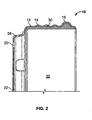
- Figure 2 shows a partial cross sectional view of the brake drum of Figure 1 .
- Figure 3 shows a perspective view of the brake drum of Figure 1 and 2 , wherein an air scoop has been installed at one of the air vents.
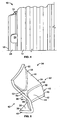
- Figure 4 shows a partial side view of the brake drum of Figure 3 , with the air scoop installed in accordance with the present invention.
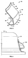
- Figure 5 shows a perspective view of the air scoop shown in Figures 3 and 4 , in accordance with the present invention.
- Figure 6 shows a partial side view of a brake drum, for use at the front of a vehicle, having the air scoop of Figure 5 installed in accordance with the present invention.
- Figure 7 shows a second embodiment of the present invention, wherein an air scoop is installed on a brake drum for use at the front of a vehicle.
- Figure 8 is a perspective view of the air scoop shown in Figure 7 , in accordance with the present invention.
- Figure 9 is a third embodiment of the present invention and it shows a partial view of a mounting flange portion of a brake drum for use at the front of a vehicle, in accordance with the present invention.
- Figure 1 discloses a two-piece composite brake drum 10.
- the brake drum shown in Figure 1 is designed for installation at the rear of a vehicle.
- Figure 1 shows a rear two-piece composite brake drum, it will become apparent, from the further description, that the present invention is not limited to a two-piece composite drum, nor a rear drum.
- the present invention relates to brake drums in general.
- the particular brake drum shown in Figure 1 includes a cylindrical main body portion or a steel shell portion 12 having a ribbed portion 14 and a squealer band 16.
- a mounting flange portion 18 is also shown and includes a plurality of lug bolt openings 20 and a pilot hole 22.
- the mounting flange portion also includes a transition portion 24 having a plurality of notches 26.
- the mounting flange portion attaches to the cylindrical main body portion with a transition portion whereupon the notches form a plurality of vent openings 28.
- Figure 2 shows a partial cross sectional view of the brake drum of Figure 1 .
- Figure 2 more readily shows the ribbed portions, and the squealer band.
- a brake linear portion or friction surface 30 is also shown.
- the mounting flange portion and steel shell portion form a brake drum cavity 32.
- FIG 3 is a perspective view of the brake drum shown in Figures 1 and 2 .
- An air scoop 34 is shown mounted at one of the vent openings in accordance with the present invention.
- Final assembly of the two-piece composite brake drum in accordance with the present invention would normally include an air scoop at each of the vent openings.
- Figure 4 is a partial side view of the brake drum of Figure 3 .
- the side view of the air scoop 34 is shown at the top left of the figure.
- FIG 5 is a perspective view of the air scoop 34 shown in Figures 3 and 4 .
- the air scoop includes a generally flat side wall 36 having a bottom edge 38, side edges 40 and an upper edge 42.
- the upper edge defines a curved or concave profile.
- a curved or concave back wall 44 extends from a first longitudinal side 46 at a substantially right angle from the upper edge.
- a curved or webbed side wall 48 extends from a second longitudinal edge 50 of the back wall at a generally inclined angle and in a radial direction and towards the outboard side of the air scoop.
- the webbed side wall includes a narrow portion 52 which extends laterally in opposite directions in a diverging manner so as to form opposing wide end portions 54.
- the narrow portion extends further radially inward than does the opposing wide end portions.
- the webbed side wall defines an inboard curved edge 56 and an outboard curved edge 58.
- a main body portion 60 extends towards the outboard side from the outboard curved edge of the webbed side wall.
- the main body portion generally conforms with the transition portion of the mounting flange portion.
- the air scoop of Figure 5 may be installed on a brake drum such as in Figures 3 and 4 via welding or similar mode of attachment such as known in the art. It will be also appreciated that the air scoop of Figure 5 and as shown installed in Figures 3 and 4 is designed to operate on a brake drum regardless of whether the brake drum is mounted to the left side or the right side of a vehicle.
- the air scoop of Figure 5 defines opposing louver openings 62 separated by a deflector surface 64 which is defined by a mid-portion 66 of the lower surface 68 of the curved or concave back wall.
- Figure 6 is a partial side view of a brake drum which is adapted for installation at the front of a vehicle.
- the brake drum of Figure 6 includes the air scoop 34 of Figure 5 .
- Figure 7 relates to a second embodiment of the present invention.
- a partial view of a brake drum is shown and which is adapted for installation at the front of a vehicle.
- the brake drum includes the cylindrical portion and the mounting flange portion having the transition portion.
- the transition portion includes a plurality of vent openings (not shown in Figure 7 ) such as disclosed in the previous figures.
- Figure 7 differs from that of Figure 6 as to the embodiment of the air scoop 70 to which is shown secured to the transition portion and the cylindrical portion, such as via welding or other similar attachment means known in the art.
- FIG 8 shows a perspective view of the air scoop 70 of Figure 7 .
- the air scoop of Figure 8 includes a flat inboard side wall 72 having an upper curved or convex edge 74, a lower edge 76 and two substantially flat side edges 78.
- a curved or convex back wall 80 is shown to include an inboard longitudinal edge 82 from which the back wall extends at a right angle from the inboard side wall.
- the back wall includes an outboard curved edge 84 from which an angled side wall 86 extends radially and towards the outboard side.
- the angled outboard side wall includes side edges 88 and a distal edge 90.
- a planar mounting flange 92 extends from the distal edge and generally conforms to the transition portion of the mounting flange.
- a deflective surface or webbed wall 94 extends generally from the flat inboard side wall, along the underside of the back wall, and to the underside of the side wall. It will be appreciated that the deflector surface or webbed wall may be substantially planar or may also be designed wherein the webbed wall extends radially outward and in a diverging manner forming a curved deflector surface on opposing sides of the louver openings 96.
- the air scoop of Figure 8 maybe secure to the two-piece composite brake drum of Figure 7 such as via welding or similar attachment means.
- Figure 9 discloses a third embodiment of the present invention.
- a partial view of the mounting flange portion of a brake drum is shown.
- the mounting flange portion is adapted for installation at the front of a vehicle.
- the mounting flange portion includes the transition portion having a plurality of vent openings (not shown) in a manner similar to that shown in the previous figures.
- An air scoop 100 is shown secured to the transition portion over a vent opening in accordance to the present invention.
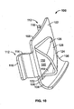
- the air scoop 100 of Figure 9 is shown in the perspective view in Figure 10 .
- the air scoop includes a generally planar main body portion 102 having a curved portion 104.
- the planar main body portion and curved portion generally conform to the transition portion of the mounting flange portion as shown in Figure 9 .
- the main body portion includes two side edges 106 and an outboard edge 108.
- An opening 110 extends through the main body portion.
- a clip 112 extends from each of the side edges.
- Each clip includes a main flange portion 114 extending radially inward, and a Up portion 116.
- a louver 118 is located over the opening 110 and defines a louver opening 120.
- the louver includes an inboard wall 122 which is substantially at a right angle to the main body portion 102, an upper wall 124 which is substantially parallel to the main body portion 102, an outboard wall 126 which is inclined at approximately a 45° angle to the main body portion 102.
- the walls 122, 124, 126 taper downwardly away from the louver opening 120 to a back side 128 of the louver at the main body portion.
- the air scoop of Figure 10 maybe installed in a brake drum via a snap fitted installation technique, wherein the clips extend through the vent opening into the brake drum cavity and the lip portion retains the scoop in position. Further, it will be appreciated that if the curved portion of the planar main body is omitted, the air scoop of Figure 10 could be installed on a brake drum regardless of which side of the vehicle the brake drum is to be installed.
- a brake drum having a plurality of air scoops in accordance with the present invention maybe installed on the vehicle.
- the air scoops will be typically secured to the transition portion and/or cylindrical main body portion, and may be located within the air gap defined between the brake drum and wheel. Rotation of the wheel and brake drum combination will induce air flow into louver opening and into the brake drum cavity providing ventilation. Ventilation will aid in cooling, cleaning and the removing of debris. It will be further appreciated that the air scoops will have a tendency to prevent water from entering the brake drum such as during washing of the vehicle and wheels.
- the present invention is applicable to a steel shell brake drum, a two-piece brake drum, a composite brake drum, a cast brake drum, and other embodiments, as will be appreciated.
Landscapes
- Engineering & Computer Science (AREA)
- General Engineering & Computer Science (AREA)
- Mechanical Engineering (AREA)
- Braking Arrangements (AREA)
- Supports For Pipes And Cables (AREA)
- Turbine Rotor Nozzle Sealing (AREA)
Applications Claiming Priority (2)
| Application Number | Priority Date | Filing Date | Title |
|---|---|---|---|
| US75401005P | 2005-12-23 | 2005-12-23 | |
| PCT/US2006/049401 WO2007076156A2 (en) | 2005-12-23 | 2006-12-26 | Brake drum with vent hole and cooling scoop |
Publications (2)
| Publication Number | Publication Date |
|---|---|
| EP1969249A2 EP1969249A2 (en) | 2008-09-17 |
| EP1969249B1 true EP1969249B1 (en) | 2010-09-29 |
Family
ID=38055166
Family Applications (1)
| Application Number | Title | Priority Date | Filing Date |
|---|---|---|---|
| EP06848227A Not-in-force EP1969249B1 (en) | 2005-12-23 | 2006-12-26 | Brake drum with vent hole and cooling scoop |
Country Status (8)
| Country | Link |
|---|---|
| US (2) | US8181753B2 (pt) |
| EP (1) | EP1969249B1 (pt) |
| CN (2) | CN101886679B (pt) |
| AT (1) | ATE483118T1 (pt) |
| BR (1) | BRPI0620424A2 (pt) |
| CA (1) | CA2634773C (pt) |
| DE (1) | DE602006017262D1 (pt) |
| WO (1) | WO2007076156A2 (pt) |
Families Citing this family (20)
| Publication number | Priority date | Publication date | Assignee | Title |
|---|---|---|---|---|
| DE102009032008A1 (de) * | 2009-07-06 | 2011-01-13 | Knorr-Bremse Systeme für Nutzfahrzeuge GmbH | Als Gussteil ausgebildete Bremstrommel |
| US9103394B2 (en) * | 2010-05-12 | 2015-08-11 | Webb Wheel Products, Inc. | Heavy duty brake drum wear indicator |
| CN103089865A (zh) * | 2011-10-28 | 2013-05-08 | 成都酷玩网络科技有限公司 | 通风散热制动鼓 |
| US9709114B2 (en) | 2012-09-11 | 2017-07-18 | Kic Llc | Vented brake drum |
| CN203202080U (zh) | 2012-09-11 | 2013-09-18 | 凯尔喜控股公司 | 通风的制动鼓 |
| US9322446B2 (en) | 2012-10-17 | 2016-04-26 | Bendix Commercial Vehicle Systems Llc | Turbo drum for drum brakes |
| US9121463B2 (en) * | 2012-11-28 | 2015-09-01 | Bendix Spicer Foundation Brake Llc | Nested composite brake drum |
| US9322443B2 (en) | 2013-09-24 | 2016-04-26 | Webb Wheel Products, Inc. | Brake drum having cooling vents |
| CN106489038B (zh) * | 2014-07-02 | 2018-12-18 | 汽车动力股份有限公司 | 鼓式制动器装置和组装方法 |
| US10690205B2 (en) | 2014-07-02 | 2020-06-23 | Autokinetics, Inc. | Drum brake device and method of assembly |
| USD779402S1 (en) * | 2014-10-17 | 2017-02-21 | Shandong Haoxin Machinery Co., Ltd. | Brake drum |
| USD784221S1 (en) * | 2015-03-24 | 2017-04-18 | Shandong Haoxin Machinery Co., Ltd. | Brake drum |
| USD777626S1 (en) * | 2015-06-19 | 2017-01-31 | Shandong Haoxin Machinery Co., Ltd. | Brake drum |
| USD784220S1 (en) * | 2015-08-17 | 2017-04-18 | Shandong Haoxin Machinery Co., Ltd. | Brake drum |
| USD794522S1 (en) * | 2016-08-30 | 2017-08-15 | Classic Auto Air Manufacturing LP | Vent accessory |
| CN107701622B (zh) * | 2017-08-01 | 2019-07-23 | 武汉理工大学 | 温控式增强型鼓式制动器 |
| US10330160B2 (en) * | 2017-11-02 | 2019-06-25 | Bendix Commercial Vehicle Systems, Llc | Devices and systems to prevent brake dust accumulation in drum brakes |
| DE102018106297B4 (de) * | 2018-03-19 | 2021-05-27 | Saf-Holland Gmbh | Mehrteilige Bremstrommel |
| CN112343941A (zh) * | 2020-11-05 | 2021-02-09 | 山东蓬翔汽车有限公司 | 一种轮边散热装置 |
| US20260043446A1 (en) * | 2024-08-08 | 2026-02-12 | Wheelnz Llc | Method of refurbishing a steel-shell brake drum |
Family Cites Families (18)
| Publication number | Priority date | Publication date | Assignee | Title |
|---|---|---|---|---|
| US1805655A (en) * | 1927-02-26 | 1931-05-19 | Westinghouse Air Brake Co | Cooling device for automotive brakes |
| US1881002A (en) * | 1930-08-29 | 1932-10-04 | Erb Joyce Foundry Company | Brake drum |
| US2088967A (en) * | 1936-08-10 | 1937-08-03 | Kelsey Hayes Wheel Co | Device for cooling brake drums |
| US2248707A (en) * | 1937-07-08 | 1941-07-08 | Motor Wheel Corp | Vehicle wheel |
| US2237164A (en) * | 1940-06-28 | 1941-04-01 | Detroit Duo Grip Brake Company | Air cooling device for brakes |
| US2489522A (en) * | 1946-09-13 | 1949-11-29 | Gen Motors Corp | Brake drum cooling and silencing device |
| US2659459A (en) * | 1949-07-12 | 1953-11-17 | Lyon George Albert | Brake drum air cooling device |
| US2701037A (en) * | 1950-11-30 | 1955-02-01 | Lyon George Albert | Detachable wheel cooling means |
| US2708011A (en) * | 1951-05-25 | 1955-05-10 | Ronning Adolph | Brake and wheel cooling means |
| US2717059A (en) * | 1951-09-11 | 1955-09-06 | Lyon George Albert | Wheel structure |
| US2754939A (en) * | 1953-09-21 | 1956-07-17 | Kelsey Hayes Wheel Co | Ventilating structure for wheel brakes |
| GB763304A (en) | 1953-09-21 | 1956-12-12 | Kelsey Hayes Wheel Co | Wheel |
| US2896749A (en) * | 1953-11-23 | 1959-07-28 | Gaylord Prod Inc | Cooling means for brake drums |
| US3127959A (en) * | 1962-03-12 | 1964-04-07 | Wengrowski Bronislaus | Cooling device for brake drums and shoes |
| DE7524641U (de) | 1975-08-02 | 1976-02-12 | Bayerische Motoren Werke Ag, 8000 Muenchen | Gegossenes speichenrad fuer kraftfahrzeuge, insbesondere fuer motorraeder |
| US4830150A (en) * | 1986-02-27 | 1989-05-16 | Lynn Denton | Brake drum cooling, drying and cleaning fins |
| US4674606A (en) * | 1986-02-27 | 1987-06-23 | Lynn Denton | Cooling and drying fins for brake drums and flywheels |
| KR20040003547A (ko) * | 2002-07-03 | 2004-01-13 | 통일중공업 주식회사 | 상용차량의 휠 허브 구조 |
-
2006
- 2006-12-26 WO PCT/US2006/049401 patent/WO2007076156A2/en not_active Ceased
- 2006-12-26 CN CN2010102123741A patent/CN101886679B/zh not_active Expired - Fee Related
- 2006-12-26 US US12/158,196 patent/US8181753B2/en active Active
- 2006-12-26 BR BRPI0620424-4A patent/BRPI0620424A2/pt not_active IP Right Cessation
- 2006-12-26 AT AT06848227T patent/ATE483118T1/de not_active IP Right Cessation
- 2006-12-26 EP EP06848227A patent/EP1969249B1/en not_active Not-in-force
- 2006-12-26 CA CA2634773A patent/CA2634773C/en active Active
- 2006-12-26 CN CN2006800489647A patent/CN101346556B/zh not_active Expired - Fee Related
- 2006-12-26 DE DE602006017262T patent/DE602006017262D1/de active Active
-
2012
- 2012-04-19 US US13/451,364 patent/US20120199426A1/en not_active Abandoned
Also Published As
| Publication number | Publication date |
|---|---|
| EP1969249A2 (en) | 2008-09-17 |
| DE602006017262D1 (de) | 2010-11-11 |
| WO2007076156A8 (en) | 2008-11-06 |
| ATE483118T1 (de) | 2010-10-15 |
| CN101346556A (zh) | 2009-01-14 |
| BRPI0620424A2 (pt) | 2011-11-08 |
| CA2634773A1 (en) | 2007-07-05 |
| CN101886679B (zh) | 2012-01-11 |
| WO2007076156A3 (en) | 2007-09-07 |
| WO2007076156A2 (en) | 2007-07-05 |
| US20090014263A1 (en) | 2009-01-15 |
| US8181753B2 (en) | 2012-05-22 |
| CN101346556B (zh) | 2010-11-17 |
| US20120199426A1 (en) | 2012-08-09 |
| CN101886679A (zh) | 2010-11-17 |
| CA2634773C (en) | 2014-11-18 |
Similar Documents
| Publication | Publication Date | Title |
|---|---|---|
| US20120199426A1 (en) | Brake Drum with Vent Hole and Cooling Scoop | |
| CN105570358B (zh) | 用于制动盘的防护装置 | |
| US11242903B2 (en) | Brake dust cover | |
| CN111656038B (zh) | 具有倾斜延伸的收集槽的盘式制动片 | |
| WO2012019270A1 (en) | Anti-dust cooling device for automotive brake drums | |
| CN105745468A (zh) | 用于机动车的摩擦片制动器的冷却空气导向系统 | |
| US20200102992A1 (en) | Vehicle braking system | |
| US20040040795A1 (en) | Brake shoe and drum brake system incorporating same | |
| AU2001293474A1 (en) | A brake shoe and drum brake system incorporating same | |
| ITRM990675A1 (it) | Dispositivo di protezione per il freno a disco di una ruota di autoveicolo con disco di cerchione. | |
| US2808908A (en) | Wheel structure with brake drum cooling means | |
| US11578770B2 (en) | Guard plate for a disk brake and disk brake | |
| ZA201001114B (en) | Disc brake assembly for a two wheel vehicle | |
| US2106702A (en) | Brake drum cooling device | |
| MX2008007919A (es) | Tembor de freno con agujero de ventilacion y toma de aire de enfriamiento | |
| EP1104370B1 (en) | Vehicle brake disc cooling | |
| JP4163672B2 (ja) | ブレーキドラム | |
| CN222782922U (zh) | 制动盘防护罩、制动总成和车辆 | |
| JPH0124931B2 (pt) | ||
| JP2011163484A (ja) | ディスクブレーキ装置 | |
| US20190178318A1 (en) | Brake carrier for a disc brake | |
| JP2008095857A (ja) | ブレーキディスクロータ | |
| CN120487794A (zh) | 一种汽车制动系统 | |
| JP2016210373A (ja) | 車両前部構造 | |
| AU2018229522A1 (en) | Device for assisting brake cooling of a vehicle in high-performance environment |
Legal Events
| Date | Code | Title | Description |
|---|---|---|---|
| PUAI | Public reference made under article 153(3) epc to a published international application that has entered the european phase |
Free format text: ORIGINAL CODE: 0009012 |
|
| 17P | Request for examination filed |
Effective date: 20080717 |
|
| AK | Designated contracting states |
Kind code of ref document: A2 Designated state(s): AT BE BG CH CY CZ DE DK EE ES FI FR GB GR HU IE IS IT LI LT LU LV MC NL PL PT RO SE SI SK TR |
|
| RAP1 | Party data changed (applicant data changed or rights of an application transferred) |
Owner name: WEBB WHEEL PRODUCTS INC. |
|
| 17Q | First examination report despatched |
Effective date: 20090525 |
|
| GRAP | Despatch of communication of intention to grant a patent |
Free format text: ORIGINAL CODE: EPIDOSNIGR1 |
|
| GRAS | Grant fee paid |
Free format text: ORIGINAL CODE: EPIDOSNIGR3 |
|
| GRAA | (expected) grant |
Free format text: ORIGINAL CODE: 0009210 |
|
| AK | Designated contracting states |
Kind code of ref document: B1 Designated state(s): AT BE BG CH CY CZ DE DK EE ES FI FR GB GR HU IE IS IT LI LT LU LV MC NL PL PT RO SE SI SK TR |
|
| REG | Reference to a national code |
Ref country code: GB Ref legal event code: FG4D |
|
| REG | Reference to a national code |
Ref country code: CH Ref legal event code: EP |
|
| REG | Reference to a national code |
Ref country code: IE Ref legal event code: FG4D |
|
| REF | Corresponds to: |
Ref document number: 602006017262 Country of ref document: DE Date of ref document: 20101111 Kind code of ref document: P |
|
| PG25 | Lapsed in a contracting state [announced via postgrant information from national office to epo] |
Ref country code: LT Free format text: LAPSE BECAUSE OF FAILURE TO SUBMIT A TRANSLATION OF THE DESCRIPTION OR TO PAY THE FEE WITHIN THE PRESCRIBED TIME-LIMIT Effective date: 20100929 Ref country code: AT Free format text: LAPSE BECAUSE OF FAILURE TO SUBMIT A TRANSLATION OF THE DESCRIPTION OR TO PAY THE FEE WITHIN THE PRESCRIBED TIME-LIMIT Effective date: 20100929 Ref country code: FI Free format text: LAPSE BECAUSE OF FAILURE TO SUBMIT A TRANSLATION OF THE DESCRIPTION OR TO PAY THE FEE WITHIN THE PRESCRIBED TIME-LIMIT Effective date: 20100929 |
|
| REG | Reference to a national code |
Ref country code: NL Ref legal event code: VDEP Effective date: 20100929 |
|
| LTIE | Lt: invalidation of european patent or patent extension |
Effective date: 20100929 |
|
| PG25 | Lapsed in a contracting state [announced via postgrant information from national office to epo] |
Ref country code: SI Free format text: LAPSE BECAUSE OF FAILURE TO SUBMIT A TRANSLATION OF THE DESCRIPTION OR TO PAY THE FEE WITHIN THE PRESCRIBED TIME-LIMIT Effective date: 20100929 |
|
| PG25 | Lapsed in a contracting state [announced via postgrant information from national office to epo] |
Ref country code: LV Free format text: LAPSE BECAUSE OF FAILURE TO SUBMIT A TRANSLATION OF THE DESCRIPTION OR TO PAY THE FEE WITHIN THE PRESCRIBED TIME-LIMIT Effective date: 20100929 Ref country code: GR Free format text: LAPSE BECAUSE OF FAILURE TO SUBMIT A TRANSLATION OF THE DESCRIPTION OR TO PAY THE FEE WITHIN THE PRESCRIBED TIME-LIMIT Effective date: 20101230 Ref country code: SE Free format text: LAPSE BECAUSE OF FAILURE TO SUBMIT A TRANSLATION OF THE DESCRIPTION OR TO PAY THE FEE WITHIN THE PRESCRIBED TIME-LIMIT Effective date: 20100929 |
|
| PG25 | Lapsed in a contracting state [announced via postgrant information from national office to epo] |
Ref country code: EE Free format text: LAPSE BECAUSE OF FAILURE TO SUBMIT A TRANSLATION OF THE DESCRIPTION OR TO PAY THE FEE WITHIN THE PRESCRIBED TIME-LIMIT Effective date: 20100929 Ref country code: RO Free format text: LAPSE BECAUSE OF FAILURE TO SUBMIT A TRANSLATION OF THE DESCRIPTION OR TO PAY THE FEE WITHIN THE PRESCRIBED TIME-LIMIT Effective date: 20100929 Ref country code: IT Free format text: LAPSE BECAUSE OF FAILURE TO SUBMIT A TRANSLATION OF THE DESCRIPTION OR TO PAY THE FEE WITHIN THE PRESCRIBED TIME-LIMIT Effective date: 20100929 Ref country code: CZ Free format text: LAPSE BECAUSE OF FAILURE TO SUBMIT A TRANSLATION OF THE DESCRIPTION OR TO PAY THE FEE WITHIN THE PRESCRIBED TIME-LIMIT Effective date: 20100929 Ref country code: NL Free format text: LAPSE BECAUSE OF FAILURE TO SUBMIT A TRANSLATION OF THE DESCRIPTION OR TO PAY THE FEE WITHIN THE PRESCRIBED TIME-LIMIT Effective date: 20100929 Ref country code: IS Free format text: LAPSE BECAUSE OF FAILURE TO SUBMIT A TRANSLATION OF THE DESCRIPTION OR TO PAY THE FEE WITHIN THE PRESCRIBED TIME-LIMIT Effective date: 20110129 Ref country code: SK Free format text: LAPSE BECAUSE OF FAILURE TO SUBMIT A TRANSLATION OF THE DESCRIPTION OR TO PAY THE FEE WITHIN THE PRESCRIBED TIME-LIMIT Effective date: 20100929 Ref country code: PT Free format text: LAPSE BECAUSE OF FAILURE TO SUBMIT A TRANSLATION OF THE DESCRIPTION OR TO PAY THE FEE WITHIN THE PRESCRIBED TIME-LIMIT Effective date: 20110131 |
|
| PG25 | Lapsed in a contracting state [announced via postgrant information from national office to epo] |
Ref country code: BE Free format text: LAPSE BECAUSE OF FAILURE TO SUBMIT A TRANSLATION OF THE DESCRIPTION OR TO PAY THE FEE WITHIN THE PRESCRIBED TIME-LIMIT Effective date: 20100929 |
|
| PG25 | Lapsed in a contracting state [announced via postgrant information from national office to epo] |
Ref country code: ES Free format text: LAPSE BECAUSE OF FAILURE TO SUBMIT A TRANSLATION OF THE DESCRIPTION OR TO PAY THE FEE WITHIN THE PRESCRIBED TIME-LIMIT Effective date: 20110109 Ref country code: MC Free format text: LAPSE BECAUSE OF NON-PAYMENT OF DUE FEES Effective date: 20101231 |
|
| REG | Reference to a national code |
Ref country code: CH Ref legal event code: PL |
|
| PLBE | No opposition filed within time limit |
Free format text: ORIGINAL CODE: 0009261 |
|
| STAA | Information on the status of an ep patent application or granted ep patent |
Free format text: STATUS: NO OPPOSITION FILED WITHIN TIME LIMIT |
|
| PG25 | Lapsed in a contracting state [announced via postgrant information from national office to epo] |
Ref country code: DK Free format text: LAPSE BECAUSE OF FAILURE TO SUBMIT A TRANSLATION OF THE DESCRIPTION OR TO PAY THE FEE WITHIN THE PRESCRIBED TIME-LIMIT Effective date: 20100929 Ref country code: PL Free format text: LAPSE BECAUSE OF FAILURE TO SUBMIT A TRANSLATION OF THE DESCRIPTION OR TO PAY THE FEE WITHIN THE PRESCRIBED TIME-LIMIT Effective date: 20100929 |
|
| REG | Reference to a national code |
Ref country code: DE Ref legal event code: R097 Ref document number: 602006017262 Country of ref document: DE Effective date: 20110630 |
|
| PG25 | Lapsed in a contracting state [announced via postgrant information from national office to epo] |
Ref country code: CH Free format text: LAPSE BECAUSE OF NON-PAYMENT OF DUE FEES Effective date: 20101231 Ref country code: IE Free format text: LAPSE BECAUSE OF NON-PAYMENT OF DUE FEES Effective date: 20101226 Ref country code: LI Free format text: LAPSE BECAUSE OF NON-PAYMENT OF DUE FEES Effective date: 20101231 |
|
| PG25 | Lapsed in a contracting state [announced via postgrant information from national office to epo] |
Ref country code: CY Free format text: LAPSE BECAUSE OF FAILURE TO SUBMIT A TRANSLATION OF THE DESCRIPTION OR TO PAY THE FEE WITHIN THE PRESCRIBED TIME-LIMIT Effective date: 20100929 |
|
| PG25 | Lapsed in a contracting state [announced via postgrant information from national office to epo] |
Ref country code: LU Free format text: LAPSE BECAUSE OF NON-PAYMENT OF DUE FEES Effective date: 20101226 Ref country code: BG Free format text: LAPSE BECAUSE OF FAILURE TO SUBMIT A TRANSLATION OF THE DESCRIPTION OR TO PAY THE FEE WITHIN THE PRESCRIBED TIME-LIMIT Effective date: 20100929 Ref country code: HU Free format text: LAPSE BECAUSE OF FAILURE TO SUBMIT A TRANSLATION OF THE DESCRIPTION OR TO PAY THE FEE WITHIN THE PRESCRIBED TIME-LIMIT Effective date: 20110330 |
|
| PG25 | Lapsed in a contracting state [announced via postgrant information from national office to epo] |
Ref country code: TR Free format text: LAPSE BECAUSE OF FAILURE TO SUBMIT A TRANSLATION OF THE DESCRIPTION OR TO PAY THE FEE WITHIN THE PRESCRIBED TIME-LIMIT Effective date: 20100929 |
|
| PG25 | Lapsed in a contracting state [announced via postgrant information from national office to epo] |
Ref country code: BG Free format text: LAPSE BECAUSE OF FAILURE TO SUBMIT A TRANSLATION OF THE DESCRIPTION OR TO PAY THE FEE WITHIN THE PRESCRIBED TIME-LIMIT Effective date: 20101229 |
|
| PGFP | Annual fee paid to national office [announced via postgrant information from national office to epo] |
Ref country code: DE Payment date: 20131230 Year of fee payment: 8 Ref country code: GB Payment date: 20131227 Year of fee payment: 8 |
|
| PGFP | Annual fee paid to national office [announced via postgrant information from national office to epo] |
Ref country code: FR Payment date: 20131217 Year of fee payment: 8 |
|
| REG | Reference to a national code |
Ref country code: DE Ref legal event code: R119 Ref document number: 602006017262 Country of ref document: DE |
|
| GBPC | Gb: european patent ceased through non-payment of renewal fee |
Effective date: 20141226 |
|
| REG | Reference to a national code |
Ref country code: FR Ref legal event code: ST Effective date: 20150831 |
|
| PG25 | Lapsed in a contracting state [announced via postgrant information from national office to epo] |
Ref country code: DE Free format text: LAPSE BECAUSE OF NON-PAYMENT OF DUE FEES Effective date: 20150701 Ref country code: GB Free format text: LAPSE BECAUSE OF NON-PAYMENT OF DUE FEES Effective date: 20141226 |
|
| PG25 | Lapsed in a contracting state [announced via postgrant information from national office to epo] |
Ref country code: FR Free format text: LAPSE BECAUSE OF NON-PAYMENT OF DUE FEES Effective date: 20141231 |