EP1969335B1 - Système et procédé pour la séparation de la voix d'un utilisateur du son ambiant - Google Patents
Système et procédé pour la séparation de la voix d'un utilisateur du son ambiant Download PDFInfo
- Publication number
- EP1969335B1 EP1969335B1 EP06846980.8A EP06846980A EP1969335B1 EP 1969335 B1 EP1969335 B1 EP 1969335B1 EP 06846980 A EP06846980 A EP 06846980A EP 1969335 B1 EP1969335 B1 EP 1969335B1
- Authority
- EP
- European Patent Office
- Prior art keywords
- user
- microphone
- audio signal
- ear
- voice
- Prior art date
- Legal status (The legal status is an assumption and is not a legal conclusion. Google has not performed a legal analysis and makes no representation as to the accuracy of the status listed.)
- Active
Links
Images


Classifications
-
- H—ELECTRICITY
- H04—ELECTRIC COMMUNICATION TECHNIQUE
- H04R—LOUDSPEAKERS, MICROPHONES, GRAMOPHONE PICK-UPS OR LIKE ACOUSTIC ELECTROMECHANICAL TRANSDUCERS; ELECTRIC HEARING AIDS; PUBLIC ADDRESS SYSTEMS
- H04R3/00—Circuits for transducers
- H04R3/005—Circuits for transducers for combining the signals of two or more microphones
-
- G—PHYSICS
- G10—MUSICAL INSTRUMENTS; ACOUSTICS
- G10L—SPEECH ANALYSIS TECHNIQUES OR SPEECH SYNTHESIS; SPEECH RECOGNITION; SPEECH OR VOICE PROCESSING TECHNIQUES; SPEECH OR AUDIO CODING OR DECODING
- G10L21/00—Speech or voice signal processing techniques to produce another audible or non-audible signal, e.g. visual or tactile, in order to modify its quality or its intelligibility
- G10L21/02—Speech enhancement, e.g. noise reduction or echo cancellation
- G10L21/0272—Voice signal separating
-
- H—ELECTRICITY
- H04—ELECTRIC COMMUNICATION TECHNIQUE
- H04R—LOUDSPEAKERS, MICROPHONES, GRAMOPHONE PICK-UPS OR LIKE ACOUSTIC ELECTROMECHANICAL TRANSDUCERS; ELECTRIC HEARING AIDS; PUBLIC ADDRESS SYSTEMS
- H04R1/00—Details of transducers, loudspeakers or microphones
- H04R1/10—Earpieces; Attachments therefor ; Earphones; Monophonic headphones
- H04R1/1016—Earpieces of the intra-aural type
-
- H—ELECTRICITY
- H04—ELECTRIC COMMUNICATION TECHNIQUE
- H04R—LOUDSPEAKERS, MICROPHONES, GRAMOPHONE PICK-UPS OR LIKE ACOUSTIC ELECTROMECHANICAL TRANSDUCERS; ELECTRIC HEARING AIDS; PUBLIC ADDRESS SYSTEMS
- H04R25/00—Electric hearing aids
- H04R25/40—Arrangements for obtaining a desired directivity characteristic
- H04R25/407—Circuits for combining signals of a plurality of transducers
-
- H—ELECTRICITY
- H04—ELECTRIC COMMUNICATION TECHNIQUE
- H04R—LOUDSPEAKERS, MICROPHONES, GRAMOPHONE PICK-UPS OR LIKE ACOUSTIC ELECTROMECHANICAL TRANSDUCERS; ELECTRIC HEARING AIDS; PUBLIC ADDRESS SYSTEMS
- H04R1/00—Details of transducers, loudspeakers or microphones
- H04R1/10—Earpieces; Attachments therefor ; Earphones; Monophonic headphones
- H04R1/1083—Reduction of ambient noise
-
- H—ELECTRICITY
- H04—ELECTRIC COMMUNICATION TECHNIQUE
- H04R—LOUDSPEAKERS, MICROPHONES, GRAMOPHONE PICK-UPS OR LIKE ACOUSTIC ELECTROMECHANICAL TRANSDUCERS; ELECTRIC HEARING AIDS; PUBLIC ADDRESS SYSTEMS
- H04R2225/00—Details of deaf aids covered by H04R25/00, not provided for in any of its subgroups
- H04R2225/021—Behind the ear [BTE] hearing aids
- H04R2225/0216—BTE hearing aids having a receiver in the ear mould
-
- H—ELECTRICITY
- H04—ELECTRIC COMMUNICATION TECHNIQUE
- H04R—LOUDSPEAKERS, MICROPHONES, GRAMOPHONE PICK-UPS OR LIKE ACOUSTIC ELECTROMECHANICAL TRANSDUCERS; ELECTRIC HEARING AIDS; PUBLIC ADDRESS SYSTEMS
- H04R2225/00—Details of deaf aids covered by H04R25/00, not provided for in any of its subgroups
- H04R2225/023—Completely in the canal [CIC] hearing aids
-
- H—ELECTRICITY
- H04—ELECTRIC COMMUNICATION TECHNIQUE
- H04R—LOUDSPEAKERS, MICROPHONES, GRAMOPHONE PICK-UPS OR LIKE ACOUSTIC ELECTROMECHANICAL TRANSDUCERS; ELECTRIC HEARING AIDS; PUBLIC ADDRESS SYSTEMS
- H04R2225/00—Details of deaf aids covered by H04R25/00, not provided for in any of its subgroups
- H04R2225/025—In the ear hearing aids [ITE] hearing aids
-
- H—ELECTRICITY
- H04—ELECTRIC COMMUNICATION TECHNIQUE
- H04R—LOUDSPEAKERS, MICROPHONES, GRAMOPHONE PICK-UPS OR LIKE ACOUSTIC ELECTROMECHANICAL TRANSDUCERS; ELECTRIC HEARING AIDS; PUBLIC ADDRESS SYSTEMS
- H04R2225/00—Details of deaf aids covered by H04R25/00, not provided for in any of its subgroups
- H04R2225/43—Signal processing in hearing aids to enhance the speech intelligibility
Definitions
- the present invention relates to a system and a method for separation of a user's voice from ambient sound by using at least one device to be worn at the user's ear or at least partly in the user's ear canal.
- a sound pick-up system which is capable at least to some extent to separate the user's voice from ambient noise, or generally ambient sound, in order to improve the intelligibility of the person's speech to the listener, who may be one of the other persons exposed to the noisy environment or who may be a remote person.
- a common approach to achieve such separation of a person's voice is the use of a boom microphone, i.e. a microphone which is placed close to the mouth, carried by a headset, helmet or any other device worn by the person.
- a boom microphone i.e. a microphone which is placed close to the mouth, carried by a headset, helmet or any other device worn by the person.
- Such microphone selectively emphasizes the near field around the mouth.
- vibration pick-up devices which are in direct contact with the throat, picking up the vibrations of the vocal chord, or which are in direct contact with the meatus wall or the outer ear canal, picking up the vibrations of the head tissue (i.e. "bone conduction” microphones) or which are in direct contact with the cheek-bone.
- US 6,661,901 B1 relates to an active hearing protection system comprising an earplug with an outer microphone for picking up ambient sound and an inner microphone which is sealed with respect to ambient sound but is open towards the inner part of the user's ear canal.
- an operation mode in which separation of the user's voice from ambient noise is desired only the inner microphone is activated while the outer microphone is not, with the signal from the inner microphone being processed by an electronics unit integrated within the earplug in order to make the user's voice highly natural and intelligible, either for the user himself or his external communication partners.
- US 2003/0055535 A1 relates to the use of a BSS algorithm for separating the voice of an operator of a vehicle wheel alignment system with a voice audio interface from background noise by using a microphone array in order to avoid the necessity to use a headset.
- US 2005/0060142 A1 relates in a more general manner to the use of two spaced-apart microphones operated with a BSS algorithm for voice separation from background noise in audio applications.
- EP 1 509 065 A1 relates to a binaural hearing aid system wherein the audio signals captured by the microphone of the right ear hearing aid and the microphone of the left ear hearing aid undergo a BSS algorithm, followed by additional signal processing, in order to increase the intelligibility of speech in background noise by the user of the hearing aid system.
- the invention is beneficial in that, by using a first microphone and a second microphone, wherein according to the solution of claims 1 and 14 the first microphone is oriented acoustically outwardly towards the environment and the second microphone oriented acoustically inwardly towards the user's ear canal and according to the solution of claims 11 and 15 the first microphone is located at the right ear and the second microphone is located at the left ear, and by processing the audio signals from the first and second microphone by a blind source separation algorithm, good separation of the user's voice from ambient sound with resulting high intelligibility of the user's speech is achieved without the need for additional restrictions regarding the location of the microphones, so that in particular the need for a boom microphone or a bone-conduction microphone can be avoided.
- blind source separation also referred to as “independent component analysis” (ICA)
- ICA independent component analysis
- blind source separation applies an "un-mixing" matrix of weights to the mixed signals, for example, multiplying the matrix with the mixed signals, to produce separated signals.
- the weights are assigned initial values, and then adjusted to maximize joint entropy of the signals in order to minimize information redundancy. This weight-adjusting and entropy-increasing process is repeated until the information redundancy of the signals is reduced to a minimum. Because this technique does not require information on the source of each signal, it is referred to as “blind source separation”.
- An introduction to blind source separation is found, for example, in US 2005/0060142 A1 .
- BSS is applied to two different mixtures of two (acoustic) sources, wherein the two different mixtures are obtained by using two spaced apart microphones.
- Mixing of the two sources can be represented by a matrix A, with the BSS algorithm corresponding mathematically to finding the inverse matrix of A without knowing anything about the matrix nor about the sources, except that they are statistically independent.
- the latter assumption usually is valid.
- the mixtures of the two sources could be different with respect to amplitude and/or phase of the two sources.
- the signal of each of these microphones will correspond to a mixture which is different with regard to the difference in amplitude and/or phase of the two acoustic sources (i.e. user's voice on the one hand and ambient noise on the other hand).
- the microphones By orienting one of the microphones outwardly towards the environment and the other microphone inwardly to the ear canal, a particularly large difference between the two mixtures can be obtained in a simple and particularly comfortable manner, i.e. no boom microphones or bone-conduction microphones which would cause discomfort to the user need to be used.
- the two microphones are part of a hearing protection device.
- the microphones can be arranged such that the ambient sound reaching the inwardly oriented microphone is attenuated by the hearing protection device relative to ambient sound reaching the outwardly oriented microphone.
- the hearing protection device could be an earmuff
- the hearing protection device is an earplug comprising a shell which is to be inserted at least partially into the user's ear canal.
- the shell is a customized hard shell having an elasticity from shore D85 to D65 and having an outer shape according to the measured inner shape of the user's outer ear and ear canal.
- the shell is a generic soft shell capable of adapting to the shape of the user's outer ear and ear canal.
- the inwardly oriented microphone is located at or is open to the inner part of the shell which is to be inserted into the ear canal, with the inwardly oriented microphone preferably being located at the inner end of the shell or within a channel of the shell open to the inner end of the shell.
- the outwardly oriented microphone is located at or is open to the outer part of the shell which is not to be inserted into the ear canal, with the outwardly oriented microphone preferably being located at the outer end of the shell or within a channel of the shell open to the outer end of the shell.
- the hearing protection device is an earmuff
- the first microphone is located at or is open to the outer side of the earmuff and the second microphone is located at or is open to the inner side of the earmuff.
- the device preferably comprises a speaker adapted to provide an external audio signal to the user's ear.
- the speaker is located at or is open to a portion of the device which is to be worn within the user's ear canal, whereby the speaker is brought acoustically close to the user's ear drum so that good intelligibility of the sound provided by the speaker is achieved even in noisy environments.
- the device will be binaural, i.e. it will comprise one unit for the right ear and another unit for the left ear.
- the speaker and the microphones may be integrated in the same unit, i.e. in at least one of the units, or the speaker may be part of the unit for one ear and the microphones may be part of the unit for the other ear.
- the device may be adapted to be worn completely within the user's ear canal, whereby the device can be more or less completely hidden from the views of other persons.
- the device may be any other kind of a wired or wireless headset.
- the audio signal processing unit is integrated within the device.
- the audio signal processing unit may be adapted to be worn behind the user's ear or somewhere at the user's body.
- the audio signal processing unit may be connected to the microphone either by wires, which is the most simple solution, or via a wireless link, for example, a radio frequency link such as Bluetooth link, an inductive link or an infrared link, which solution would result in enhanced wearing comfort for the user.
- the audio signal processing unit could be designed to be located remote from the user and is connected to the microphones via a radio frequency link such as Bluetooth link. In this case, there would be even less restrictions regarding the size and power consumption of the audio signal processing unit, which might result in reduced costs and/or increased performance of the blind source separation.
- the system preferably comprises a radio frequency transmitter for transmitting the processed audio signal output of the audio signal processing unit to a remote radio frequency receiver in order to provide the user's voice to another person.
- the radio frequency transmitter is integrated within the audio signal processing unit, i.e. the radio frequency transmitter may be either integrated within the device or it may be adapted to be worn behind the use's ear or at the user's body or it could be even located remote from the user.
- the radio frequency transmitter could be remote from the audio signal processing unit, in which case the processed audio signal output of the audio signal processing unit would be provided to a radio frequency transmitter by wires or via a radio frequency link, an inductive link or an infrared link. In this case the location of the audio signal processing unit and the radio frequency transmitter can be optimized independently form each other.
- the blind source separation algorithm preferably works in the frequency domain, i.e. the algorithm is simultaneously carried out in different frequency bands/bins and the outcomes of these bands/bins are combined in an appropriate way.
- the blind source separation algorithm preferably works with the assumption that the sources are statistically independent, i.e. that the user's voice is independent of the ambient sound.
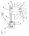
- the system of Fig. 1 comprises a device 10 designed as a hearing protection earplug which may have a hard shell with an elasticity from shore D85 to shore D65, which is customized, i.e. it has an outer shape according to the individual measured inner shape of the user's outer ear and ear canal.
- the hard shell may be manufactured by layer-by-layer laser sintering of a powder material, for example, polyamide powder, or by laser stereo-lithography or photopolymerization.
- An overview regarding such additive layer-by-layer build-up processes for manufacturing customized shells of hearing devices can be found, for example, in US 2003/0133583 A1 or US 6,533,062 B1 .
- the inner shape of the person's ear canal and outer ear can be measured, for example, by taking an impression which then undergoes laser scanning or by direct laser scanning of the ear.
- the hard shell is designed such that it provides for an acoustic attenuation, averaged over the audible frequency range, of at least 10 dB when inserted into the user's ear canal.
- earplug 10 may have a generic soft shell which adapts to the shape of the users outer ear and ear canal due to its elasticity.
- Fig. 1 the earplug 10 is shown to be inserted with its inner end portion into a user's ear canal 12.
- the earplug 10 comprises an outer microphone M1, which is located at the outer part of the earplug 10 and which is open to the outer end 14 of the earplug 10 via a sound channel 16, and an inner microphone M2, which is located at the inner part of the earplug 10 and which is open to the inner end 18 of the earplug 10 via a sound channel 20.
- the earplug 10 further comprises a speaker S which is likewise located at the inner part of the earplug 10 and is open to the inner end 18 via a sound channel 22.
- the earplug 10 also includes a digital audio signal processing unit 24 comprising a digital signal processor as well as a radio frequency transmitter unit T1 and a radio frequency receiver unit R1.
- the audio signal processing unit 24 functionally includes a unit 26 for applying a blind source separation algorithm to the audio signals provided by the microphones M1 and M2.
- the earplug 10 includes additional electrical components, such as amplifiers and analogue-to-digital converters for the audio signals provided by the microphones M1 and M2, a digital-to-analogue converter and an amplifier for the audio signal to be transformed into sound by the speaker S, program and data memory components for the audio signal processing unit 24, a battery for power supply, a demodulator, a modulator, an antenna, etc., which are not shown in Fig. 1 for the sake of simplicity.
- the transmitter T1 of the earplug 10 is adapted to transmit audio signals from the earplug 10 to a remote receiver R2 via a radio link, while the receiver R1 of the earplug 10 is adapted to receive audio signals from a remote transmitter T2.
- the audio signals received by the receiver R1 are demodulated and then undergo signal processing in the audio signal processing unit 24 as input to the speaker S in order to provide remote audio signals to the user.
- Such remote audio signals could be the speech of another person picked up by a microphone whose output is sent to the remote transmitter T2 by wires or via, for example, a mobile telephone or mobile radio device.
- the audio signals provided by the microphones M1 and M2 are passed as input to the blind source separation unit 26, in which a processed audio signal output for the transmitter T1 is produced, with the processed audio signal output consisting completely or at least essentially of the user's voice which has been separated from the ambient sound by action of the blind source separation algorithm carried out in the BSS unit 26.
- BSS signal processing utilizes the fact that the sound mixtures picked up by the microphone M1 which is oriented towards the environment and M2 which is oriented towards the ear canal 12, respectively, consist - due to the different orientation of the microphones M1 and M2 - of essentially different mixtures of the ambient sound and the user's voice, which are different regarding amplitude ratio of these two signal contributions or sources (i.e. ambient sound on the one hand and user's voice on the other hand) and regarding phase difference of these two signal contributions of the mixture.
- the output signal of the BSS unit 26 is transmitted via the transmitter T1 to the remote receiver R2 which usually will be connected to a remote speaker for presenting the user's voice to another person.
- the remote speaker and the remote microphone connected to the remote transmitter T2 could be part of an earpiece or an earplug worn by another person, which may be similar or identical to the earplug 10.
- in-the-ear hearing protection devices with integrated communication function can be achieved.
- Such a system could be used by any persons who need to communicate in a noisy environment, such as workers, soldiers, firemen, etc.
- the remote receiver R2 also might serve for communication via a mobile telephone or a mobile radio device.
- the remote receiver R2 / transmitter T2 could be a part of an interface of a standard wireless communication device, such as a mobile telephone device or a mobile radio device
- a standard wireless communication device such as a mobile telephone device or a mobile radio device
- the wireless link between the transmitter T1 / receiver R1 and the remote receiver R2 / remote transmitter T2 is a Bluetooth link.
- the remote receiver R2 / transmitter T2 then could be a part of the Bluetooth interface of a standard wireless communication device, such as a mobile telephone device or a mobile radio device.
- the audio signal produced by the microphones M1 and M2, which is used as input to the BSS unit 26, in addition could undergo other audio signal processing within the audio signal processing unit 24, for example, in order to provide the ambient sound picked up by the microphone M1 to the speaker S for enabling perception of desired ambient sounds during times when the noise level is low so that the hearing protection function provided by the earplug 10 is not needed, or to provide for an in-situ measurement of the actual acoustic attenuation provided by the earplug 10 when inserted into the user's ear canal 12 by comparing the sound levels measured by the microphones M1 and M2.
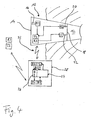
- Fig. 2 a modified embodiment is shown, wherein the transmitter T1 and the receiver R1 have been removed from the earplug 10 and now are located in an external unit 28 which is connected by wires 30 to the earplug 10 and which is to be worn at an appropriate location at the user's body, for example behind the user's ear or somewhere within or below the user's clothing, for example, within a helmet.
- the external unit 28 may include further electrical components removed from the earplug 10, for example, the power supply battery.
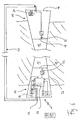
- Fig. 3 a further modified embodiment is shown, wherein not only the transmitter T1 and the receiver R1 (and the power supply battery) but in addition also the audio signal processing unit 24 including the BSS unit 26 has been removed from the earplug 10 and is connected via corresponding wires to the microphones M1 and M2 and the speaker S, respectively.
- a still further modified embodiment is shown, wherein the wire connection 30 between the earplug 10 and the external unit 28 has been replaced by a bidirectional wireless link 32, which is established by a transmitter T3 and a receiver R3 located in the earplug 10 and a corresponding receiver R4 and transmitter T4 located in the external unit 28.
- the wireless link 32 could be a radio frequency link, an inductive link or an infrared link. If it is an inductive link, the external unit 28 would have to be located relatively close to the earplug 10, for example at a distance of not more than 20 cm.
- the distance could be larger; in this case it would be even be possible to locate the external unit 28 at a position remote from the user's body, for example, within a distance of a few meters.
- the wireless link 32 of the embodiment of Fig. 4 is a Bluetooth link.
- the speaker S is shown as being integrated. in the same earplug 10 as the microphones M1 and M2, in other embodiments the speaker S may be provided at an earplug other than the earplug at which the microphones M1 and M2 are provided.
- Fig. 5 shows a modified version of the embodiment of Fig. 1 , wherein the inwardly oriented second microphone M2 is not part of the earplug 10 - as shown in Fig. 1 - but rather is provided at the earplug 11 for the other ear.
- the second microphone M2 is located at the inner part of the earplug 11 and is open to the inner end 18 of the earplug 11 via a sound channel 20.
- the earplug 11 further comprises a speaker S which is likewise located at the inner part of the earplug 11 and is open to the inner end 18 via a sound channel 22.
- the microphone M2 and the speaker S of the earplug 11 are connected to the audio signal processing unit 24 located in the earplug 10 via a wire connection 40 which be integrated in a mechanical connection (not shown) between the earplugs 10 and 11 which may be provided for preventing loss of the earplugs 10, 11.
- the outwardly oriented first microphone M1 may be provided at the earplug 11, while the inwardly oriented second microphone M2 may be provided at the earplug 10 as in Fig. 1 .
- FIG. 6 An alternative modification of the embodiment of Fig. 5 is shown in Fig. 6 , wherein both the first microphone M1 of the earplug 10 and the second microphone M2 of the earplug 11 are outwardly oriented.
- the differences in the sound mixtures picked up by the microphone M1 of the earplug 10 and the microphone M2 of the earplug 11 are due to the different location of the microphone M1 at one ear and the microphone M2 at the other ear (for example, a disturbing noise source usually will be located closer to one of the two ears and hence will contribute more strongly and with different phase to the signal picked up by the microphone located at that ear than to that located at the other ear).
- both microphones M1 and M2 could be inwardly oriented rather than outwardly oriented.
- FIGs. 5 and 6 and the above-discussed variants thereof are modifications of the embodiment of Fig. 1 , according to which both the audio signal processing unit 24 and the transmitter T1 / receiver R1 are part of the earplug 10, it is to be understood that the embodiments of Figs. 2 to 4 may be analogously modified, i.e. by providing the second microphone M2 at the earplug 11 rather than at the earplug 10.
- the invention also may be applied to earmuffs serving as a hearing protection device or generally to any kind of headset, i.e. also to hearing devices which do not provide for a hearing protection function.
- the headset may consist of a device with a customized or a generic shell which is designed such that it can be worn completely in the ear canal 12 (i.e. as a "CIC device") and which serves exclusively communication purposes, for example, for security persons, policemen, firemen, etc., i.e. for persons who are exposed to a noisy environment, with the noise level, however, being below a threshold value which would require the use of hearing protection devices.
- Such CIC device generally could have the construction of the earplug of Fig. 1 , however, without considerable acoustic attenuation provided due to the material and the design of the shell, and would be reduced in size so that it can be worn completely within the ear canal 12.
- the device need not be designed as an earplug but it may rather be any kind of headset.
- oriented acoustically outwardly towards the environment it is meant that the respective microphone is acoustically open to the environment, whereas by “oriented acoustically outwardly towards the user's ear canal” it is meant that the respective microphone is acoustically open to the user's ear canal.
- This does not necessarily imply that there is line-of-sight connection to the environment or the ear canal, respectively; rather, it is sufficient that there is an acoustic connection to the environment or the ear canal, respectively, for example by a sound channel or a sound tube.
- earplug any device is meant which is to be worn in the ear canal or in the concha, so that also earmolds, i.e. devices to be worn in the concha rather than in the ear canal, are included.
- Fig. 7 an embodiment is shown, wherein the device 10, in contrast to the embodiments shown in Figs. 1 to 6 , is not designed as a hearing protection earplug but rather as a hearing instrument to be worn behind the user's ear, with the design corresponding to that of a BTE hearing instrument.
- the device 10 comprises a housing 50 to be worn behind the user's ear, with a sound tube 52 extending from the housing 50 to an earplug 54 to be worn in the user's ear canal or concha, respectively.
- the earplug 54 is provided at the free end of the sound tube 52, while at the other end the speaker S and the microphone M2 are provided in order to acoustically connect the speaker S and the microphone M2 to the user's ear canal.
- the earplug 54 usually will not act as a hearing protection device.
- the housing 50 in addition to the speaker S and the microphone M2, also includes an outwardly oriented microphone M1, an audio signal processing unit 24 with a BSS unit 26, a RF transmitter unit T1, a RF receiver unit R1 and a power supply 56.
- the functionality of the electronic components may correspond, for example, to that of the embodiment of Fig. 1 , i.e. the audio signals captured by the outwardly oriented microphone M1 and the inwardly oriented microphone M2 are supplied to the BSS unit 26 in order to extract the user's voice from ambient sound, and the output signal of the BSS unit 26 is transmitted via the transmitter unit T1 to an external receiver unit (not shown) for supplying the user's voice to, for example, another person.
- External audio signals may be received by the receiver unit R1 and may be supplied via the audio signal processing unit 24 and the speaker S to the user.
- the audio signals captured by the outwardly oriented microphone M1 may be processed in the audio signal processing unit 24 and then may be supplied to the user's ear via the speaker S, whereby the device 10 may function as a hearing aid.
- Fig. 8 a modified version of embodiment of Fig. 7 is shown, wherein both the speaker S and the microphone M2 are provided directly in the earplug 54 rather than being acoustically. connected to the earplug 54 via a sound tube 52 as in Fig. 7 .
- the speaker S and the microphone M2 are connected to the housing 50 and to the audio signal processing unit 24 via a cable connection 58.
- the device 10 is designed as a headset comprising a housing 50 which is to be worn below the user's ear and is fixed to the user's pinna by means of a loop 60 which may be made of wire and which is adjustable to the individual size of the user's pinna.
- the housing 50 is provided with an adjustment element which is fixed to one end of the loop and through which the other end 64 of the loop is guided in such a manner that it can be fixed in various positions.
- the size of the loop 60 can be adjusted by the user by pulling at the free end 64 of the loop 60.
- Such a loop is described, for example, in the German Patent Application 10 2006 016 052.5 or in DE 10 2005 002 482 B3 .
- the audio signal processing unit 24, the receiver unit R1, the transmitter unit T1 and the power supply may be integrated in a separate housing 50A, which is electrically and mechanically connected via a connector 66 to the housing 50 which includes the microphones M1 and M2 and the speaker S.
- the transmission unit T1 and the receiver unit R1 serve to establish a bi-directional wireless link to communication devices, such as a mobile phone or a walkie-talkie.
- element 56 is a power supply, such as a primary or rechargeable battery.
- the speaker S and the microphone M2 are located at one end of a sound tube 52 which extends with its free end 68 into the user's ear canal.
- the free end 68 may be provided with an earplug.
- the housing 50A with the electronic components 24, T1, R1, and power supply 56 included therein forms a communication unit which, on the one hand, receives external audio signals from a communication device, which are reproduced via the speaker S to the user's ear.
- the communication device extracts the user's voice by blind source separation of audio signals from the microphones M1 and M2 in the BSS unit 26, with the separated audio signals corresponding to the user's voice and being transmitted to the communication device.
- the housing 50 in addition to the inwardly oriented microphone M2, the speaker S, and the outwardly oriented microphone M1 may also include the audio signal processing unit 24 with the BSS unit 26, the RF transmitter unit T1, the RF receiver unit R1 and the power supply 56. In this case the additional housing 50A would be obsolete.
- FIG. 10 A modification of the embodiment of Fig. 9 is shown in Fig. 10 , wherein a cable connector 70, rather than the communication unit 50A of Fig. 9 , is received in the connector 66.
- the cable connector 70 serves to connect the microphones M1 and M2 and the speaker S to an external audio signal processing unit (not shown) which includes a BSS unit in order to apply BSS to the signals of the microphones M1 and M2 in order to separate the user's voice.
- This external audio signal processing unit also is connected to a communication device in order to supply the user's voice to such communication device and to receive external audio signals which are to be reproduced by the speaker S.
Landscapes
- Engineering & Computer Science (AREA)
- Signal Processing (AREA)
- Physics & Mathematics (AREA)
- Acoustics & Sound (AREA)
- Health & Medical Sciences (AREA)
- Otolaryngology (AREA)
- General Health & Medical Sciences (AREA)
- Computational Linguistics (AREA)
- Quality & Reliability (AREA)
- Audiology, Speech & Language Pathology (AREA)
- Human Computer Interaction (AREA)
- Multimedia (AREA)
- Neurosurgery (AREA)
- Headphones And Earphones (AREA)
Claims (15)
- Système pour séparer la voix d'un utilisateur d'un son ambiant, comprenant un dispositif (10) devant être porté à l'oreille de l'utilisateur ou au moins partiellement dans le canal auditif (12) de l'utilisateur, comprenant un premier microphone (M1) orienté acoustiquement vers l'extérieur et vers l'environnement et un second microphone (M2) orienté acoustiquement vers l'intérieur et vers le canal auditif de l'utilisateur, une unité de traitement de signal audio (24, 26) destinée à traiter des signaux audio provenant des premier et second microphones au moyen d'un algorithme de séparation de source aveugle apte à séparer la voix de l'utilisateur du son ambiant, et un émetteur radiofréquence (T1) destiné à émettre le signal audio traité fourni en sortie de l'unité de traitement de signal audio (24, 26) vers un récepteur radiofréquence distant (R2) afin de fournir la voix de l'utilisateur à une autre personne.
- Système selon la revendication 1, dans lequel le dispositif (10) est conçu sous la forme d'un dispositif de protection de l'audition destiné à fournir une atténuation acoustique, moyennée sur la gamme de fréquences audibles, d'au moins 10 dB.
- Système selon la revendication 2, dans lequel les microphones (M1, M2) sont agencés de façon que le son ambiant atteignant le second microphone (M2) soit atténué par le dispositif de protection de l'audition (10) par rapport au son ambiant atteignant le premier microphone (M1).
- Système selon l'une des revendications 2 ou 3, dans lequel le dispositif de protection de l'audition est un bouchon d'oreille (10) comprenant une coquille devant être insérée au moins partiellement dans le canal auditif (12) de l'utilisateur.
- Système selon l'une des revendications 1 à 3, dans lequel le dispositif de protection de l'audition est une coquille antibruit et dans lequel le premier microphone est situé ou s'ouvre sur la face extérieure de la coquille antibruit et le second microphone est situé ou s'ouvre sur la face intérieure de la coquille antibruit.
- Système selon l'une des revendications précédentes, dans lequel le dispositif comprend un haut-parleur (S) apte à fournir un signal audio externe à l'oreille de l'utilisateur.
- Système selon la revendication 1, dans lequel le boîtier (50, 50A) du dispositif (10) doit être porté à l'arrière ou en dessous de l'oreille de l'utilisateur et dans lequel un tube sonore (52) est prévu de manière à s'étendre du second microphone (M2) à l'intérieur du canal auditif de l'utilisateur.
- Système selon la revendication 7, dans lequel l'extrémité libre (68) du tube sonore (52) est munie d'un bouchon d'oreille (54).
- Système selon la revendication 1, dans lequel le boîtier (50) du dispositif doit être porté à l'arrière ou en dessous de l'oreille de l'utilisateur, dans lequel le second microphone (M2) est contenu dans un bouchon d'oreille (54) devant être inséré dans le canal auditif de l'utilisateur et/ou la conque de l'utilisateur et dans lequel le second microphone (M2) est connecté au boîtier (50) du dispositif (10) par l'intermédiaire d'un câble (58).
- Système selon la revendication 6, dans lequel le système comprend un récepteur radiofréquence (R1) destiné à recevoir le signal audio externe d'un émetteur radiofréquence distant (T2).
- Système pour la séparation de la voix d'un utilisateur d'un son ambiant, comprenant : un premier dispositif (10) devant être porté à l'oreille droite de l'utilisateur ou au moins partiellement dans le canal auditif droit (12) de l'utilisateur, un second dispositif (11) devant être porté à l'oreille gauche de l'utilisateur ou au moins partiellement dans le canal auditif gauche (12) de l'utilisateur, le premier dispositif comprenant un premier microphone (M1) et le second dispositif comprenant un second microphone (M2), une unité de traitement de signal audio (24, 26) destinée à traiter des signaux audio provenant des premier et second microphones au moyen d'un algorithme de séparation de source aveugle apte à séparer la voix de l'utilisateur du son ambiant, et un émetteur radiofréquence (T1) destiné à émettre le signal audio traité fourni en sortie de l'unité de traitement de signal audio (24, 26) vers un récepteur radiofréquence distant (R2) afin de fournir la voix de l'utilisateur à une autre personne.
- Système selon la revendication 11, dans lequel l'un du premier microphone (M1) et du second microphone (M2) est orienté vers l'extérieur et vers l'environnement et l'autre du premier microphone et du second microphone est orienté vers l'intérieur et vers le canal auditif (12) de l'utilisateur.
- Système selon l'une des revendications 11 et 12, dans lequel l'unité de traitement de signal audio (24, 26) est située dans l'un du premier dispositif (10) et du second dispositif (11) ou est apte à être portée à l'arrière de l'oreille de l'utilisateur ou sur le corps de l'utilisateur ou est conçue pour être placée à distance de l'utilisateur et est connectée aux microphones par l'intermédiaire d'une liaison radiofréquence (32) telle qu'une liaison Bluetooth.
- Procédé pour la séparation de la voix d'un utilisateur d'un son ambiant, consistant à :fournir à l'utilisateur un dispositif (10) devant être porté à l'oreille d'un utilisateur ou au moins partiellement dans le canal auditif (12) de l'utilisateur et comprenant un premier microphone (M1) orienté acoustiquement vers l'environnement et un second microphone (M2) orienté acoustiquement vers le canal auditif (12) de l'utilisateur,capter un son au moyen du premier microphone afin de créer un premier signal audio et au moyen du second microphone afin de créer un second signal audio, ettraiter les premier et second signaux audio au moyen d'un algorithme de séparation de source aveugle afin de produire un signal audio traité dans lequel la voix de l'utilisateur est séparée du son ambiant,dans lequel le signal audio traité est fourni à une autre personne par l'intermédiaire d'une liaison sans fil.
- Procédé pour la séparation de la voix d'un utilisateur d'un son ambiant, consistant à :fournir à l'utilisateur un premier dispositif (10) devant être porté à l'oreille droite d'un utilisateur ou au moins partiellement dans le canal auditif droit (12) de l'utilisateur et un second dispositif (11) devant être porté à l'oreille gauche de l'utilisateur ou au moins partiellement dans le canal auditif gauche (12) de l'utilisateur, le premier dispositif comprenant un premier microphone (M1) et le second dispositif comprenant un second microphone (M2),acquérir un son au moyen du premier microphone afin de créer un premier signal audio et au moyen du second microphone afin de créer un second signal audio, ettraiter les premier et second signaux audio au moyen d'un algorithme de séparation de source aveugle afin de produire un signal audio traité dans lequel la voix de l'utilisateur est séparée du son ambiant,dans lequel le signal audio traité est fourni à une autre personne par l'intermédiaire d'une liaison sans fil.
Priority Applications (1)
| Application Number | Priority Date | Filing Date | Title |
|---|---|---|---|
| EP06846980.8A EP1969335B1 (fr) | 2005-12-23 | 2006-11-28 | Système et procédé pour la séparation de la voix d'un utilisateur du son ambiant |
Applications Claiming Priority (3)
| Application Number | Priority Date | Filing Date | Title |
|---|---|---|---|
| EP05028366A EP1640972A1 (fr) | 2005-12-23 | 2005-12-23 | Système et méthode pour séparer la voix d'un utilisateur de le bruit de l'environnement |
| EP06846980.8A EP1969335B1 (fr) | 2005-12-23 | 2006-11-28 | Système et procédé pour la séparation de la voix d'un utilisateur du son ambiant |
| PCT/EP2006/011423 WO2007073818A1 (fr) | 2005-12-23 | 2006-11-28 | Système et procédé pour la séparation de la voix d'un utilisateur du son ambiant |
Publications (2)
| Publication Number | Publication Date |
|---|---|
| EP1969335A1 EP1969335A1 (fr) | 2008-09-17 |
| EP1969335B1 true EP1969335B1 (fr) | 2013-08-14 |
Family
ID=35694668
Family Applications (2)
| Application Number | Title | Priority Date | Filing Date |
|---|---|---|---|
| EP05028366A Withdrawn EP1640972A1 (fr) | 2005-12-23 | 2005-12-23 | Système et méthode pour séparer la voix d'un utilisateur de le bruit de l'environnement |
| EP06846980.8A Active EP1969335B1 (fr) | 2005-12-23 | 2006-11-28 | Système et procédé pour la séparation de la voix d'un utilisateur du son ambiant |
Family Applications Before (1)
| Application Number | Title | Priority Date | Filing Date |
|---|---|---|---|
| EP05028366A Withdrawn EP1640972A1 (fr) | 2005-12-23 | 2005-12-23 | Système et méthode pour séparer la voix d'un utilisateur de le bruit de l'environnement |
Country Status (3)
| Country | Link |
|---|---|
| EP (2) | EP1640972A1 (fr) |
| DK (1) | DK1969335T3 (fr) |
| WO (1) | WO2007073818A1 (fr) |
Families Citing this family (62)
| Publication number | Priority date | Publication date | Assignee | Title |
|---|---|---|---|---|
| DE102005032274B4 (de) * | 2005-07-11 | 2007-05-10 | Siemens Audiologische Technik Gmbh | Hörvorrichtung und entsprechendes Verfahren zur Eigenstimmendetektion |
| ATE527833T1 (de) * | 2006-05-04 | 2011-10-15 | Lg Electronics Inc | Verbesserung von stereo-audiosignalen mittels neuabmischung |
| EP2033489B1 (fr) | 2006-06-14 | 2015-10-28 | Personics Holdings, LLC. | Système de régulation de protection d'oreille |
| SE530137C2 (sv) * | 2006-06-27 | 2008-03-11 | Bo Franzen | Headset med strupmikrofon i kombination med en mot hörselgången ljudtätande öronhögtalare |
| EP2044804A4 (fr) | 2006-07-08 | 2013-12-18 | Personics Holdings Inc | Dispositif d'aide auditive personnelle et procédé |
| JP5295115B2 (ja) * | 2006-10-10 | 2013-09-18 | シーメンス アウディオローギッシェ テヒニク ゲゼルシャフト ミット ベシュレンクテル ハフツング | 補聴器の駆動方法および補聴器 |
| JP5232791B2 (ja) | 2006-10-12 | 2013-07-10 | エルジー エレクトロニクス インコーポレイティド | ミックス信号処理装置及びその方法 |
| WO2008060111A1 (fr) | 2006-11-15 | 2008-05-22 | Lg Electronics Inc. | Procédé et appareil de décodage de signal audio |
| US8265941B2 (en) | 2006-12-07 | 2012-09-11 | Lg Electronics Inc. | Method and an apparatus for decoding an audio signal |
| EP2102856A4 (fr) | 2006-12-07 | 2010-01-13 | Lg Electronics Inc | Procédé et appareil de traitement d'un signal audio |
| WO2007082579A2 (fr) * | 2006-12-18 | 2007-07-26 | Phonak Ag | Système de protection auditive active |
| EP2408222A1 (fr) | 2006-12-20 | 2012-01-18 | Phonak AG | Système de communication sans fil |
| CN101578656A (zh) | 2007-01-05 | 2009-11-11 | Lg电子株式会社 | 用于处理音频信号的装置和方法 |
| US8917894B2 (en) | 2007-01-22 | 2014-12-23 | Personics Holdings, LLC. | Method and device for acute sound detection and reproduction |
| WO2008095167A2 (fr) * | 2007-02-01 | 2008-08-07 | Personics Holdings Inc. | Procédé et dispositif d'enregistrement audio |
| DE102007008739A1 (de) | 2007-02-22 | 2008-08-28 | Siemens Audiologische Technik Gmbh | Hörvorrichtung mit Störsignaltrennung und entsprechendes Verfahren |
| US8195454B2 (en) | 2007-02-26 | 2012-06-05 | Dolby Laboratories Licensing Corporation | Speech enhancement in entertainment audio |
| DE102007010806B4 (de) | 2007-03-02 | 2010-05-12 | Siemens Ag | Verfahren zum Schaffen erweiterter Möglichkeiten bei der Verwendung von für den Einsatz von Registrierungsverfahren ungeeigneten Bilddaten eines Patienten und Röntgenangiographiesystem |
| US11750965B2 (en) | 2007-03-07 | 2023-09-05 | Staton Techiya, Llc | Acoustic dampening compensation system |
| WO2008124786A2 (fr) | 2007-04-09 | 2008-10-16 | Personics Holdings Inc. | Système d'enregistrement permanent de coiffure |
| US11317202B2 (en) | 2007-04-13 | 2022-04-26 | Staton Techiya, Llc | Method and device for voice operated control |
| US11217237B2 (en) | 2008-04-14 | 2022-01-04 | Staton Techiya, Llc | Method and device for voice operated control |
| US11683643B2 (en) | 2007-05-04 | 2023-06-20 | Staton Techiya Llc | Method and device for in ear canal echo suppression |
| US11856375B2 (en) | 2007-05-04 | 2023-12-26 | Staton Techiya Llc | Method and device for in-ear echo suppression |
| WO2009006418A1 (fr) * | 2007-06-28 | 2009-01-08 | Personics Holdings Inc. | Procédé et dispositif permettant l'atténuation de bruit de fond |
| US10009677B2 (en) | 2007-07-09 | 2018-06-26 | Staton Techiya, Llc | Methods and mechanisms for inflation |
| DE102007033520A1 (de) * | 2007-07-18 | 2009-01-29 | Noa Lerner | Vorrichtung zur Klangwiedergabe |
| US8867765B2 (en) * | 2008-02-06 | 2014-10-21 | Starkey Laboratories, Inc. | Antenna used in conjunction with the conductors for an audio transducer |
| US8600067B2 (en) | 2008-09-19 | 2013-12-03 | Personics Holdings Inc. | Acoustic sealing analysis system |
| US9129291B2 (en) | 2008-09-22 | 2015-09-08 | Personics Holdings, Llc | Personalized sound management and method |
| CN102177730B (zh) | 2008-10-09 | 2014-07-09 | 峰力公司 | 用于拾取用户语音的系统和操作该系统的方法 |
| US20110286608A1 (en) * | 2009-01-21 | 2011-11-24 | Phonak Ag | Earpiece communication system |
| US8705787B2 (en) * | 2009-12-09 | 2014-04-22 | Nextlink Ipr Ab | Custom in-ear headset |
| WO2011098142A1 (fr) | 2010-02-12 | 2011-08-18 | Phonak Ag | Système et procédé d'assistance auditive sans fil |
| WO2011159858A1 (fr) | 2010-06-17 | 2011-12-22 | Dolby Laboratories Licensing Corporation | Procédé et appareil pour réduire l'effet du bruit ambiant sur des auditeurs |
| WO2012069973A1 (fr) | 2010-11-24 | 2012-05-31 | Koninklijke Philips Electronics N.V. | Dispositif comprenant une pluralité de capteurs audio et procédé permettant de faire fonctionner ledit dispositif |
| EP2458586A1 (fr) * | 2010-11-24 | 2012-05-30 | Koninklijke Philips Electronics N.V. | Système et procédé pour produire un signal audio |
| US12349097B2 (en) | 2010-12-30 | 2025-07-01 | St Famtech, Llc | Information processing using a population of data acquisition devices |
| WO2012103935A1 (fr) | 2011-02-01 | 2012-08-09 | Phonak Ag | Dispositif auditif doté d'un module récepteur et procédé de fabrication d'un module récepteur |
| WO2013032317A1 (fr) * | 2011-08-26 | 2013-03-07 | Neuralogy Sdn Bhd | Dispositif de communication de canal auditif externe |
| US9216113B2 (en) | 2011-11-23 | 2015-12-22 | Sonova Ag | Hearing protection earpiece |
| WO2014075195A1 (fr) * | 2012-11-15 | 2014-05-22 | Phonak Ag | Formation de la propre voix d'un utilisateur dans un instrument d'aide auditive |
| US9167082B2 (en) | 2013-09-22 | 2015-10-20 | Steven Wayne Goldstein | Methods and systems for voice augmented caller ID / ring tone alias |
| CN104581467A (zh) * | 2013-10-11 | 2015-04-29 | 孙文宗 | 耳机麦克风、应用其的语音撷取方法与通讯方法 |
| US20150139448A1 (en) | 2013-11-18 | 2015-05-21 | International Business Machines Corporation | Location and orientation based volume control |
| US10043534B2 (en) | 2013-12-23 | 2018-08-07 | Staton Techiya, Llc | Method and device for spectral expansion for an audio signal |
| US10163453B2 (en) | 2014-10-24 | 2018-12-25 | Staton Techiya, Llc | Robust voice activity detector system for use with an earphone |
| US12268523B2 (en) | 2015-05-08 | 2025-04-08 | ST R&DTech LLC | Biometric, physiological or environmental monitoring using a closed chamber |
| US9401158B1 (en) | 2015-09-14 | 2016-07-26 | Knowles Electronics, Llc | Microphone signal fusion |
| US9779716B2 (en) | 2015-12-30 | 2017-10-03 | Knowles Electronics, Llc | Occlusion reduction and active noise reduction based on seal quality |
| US9830930B2 (en) | 2015-12-30 | 2017-11-28 | Knowles Electronics, Llc | Voice-enhanced awareness mode |
| DK3550858T3 (da) | 2015-12-30 | 2023-06-12 | Gn Hearing As | Et på hovedet bærbart høreapparat |
| US10616693B2 (en) | 2016-01-22 | 2020-04-07 | Staton Techiya Llc | System and method for efficiency among devices |
| US9812149B2 (en) | 2016-01-28 | 2017-11-07 | Knowles Electronics, Llc | Methods and systems for providing consistency in noise reduction during speech and non-speech periods |
| US9905241B2 (en) | 2016-06-03 | 2018-02-27 | Nxp B.V. | Method and apparatus for voice communication using wireless earbuds |
| SE542475C2 (en) | 2017-01-03 | 2020-05-19 | Earin Ab | A storage and charging capsule for wireless earbuds |
| WO2018128577A2 (fr) * | 2017-01-03 | 2018-07-12 | Earin Ab | Écouteurs sans fil, et capsule de stockage et de charge associée |
| US10951994B2 (en) | 2018-04-04 | 2021-03-16 | Staton Techiya, Llc | Method to acquire preferred dynamic range function for speech enhancement |
| US11206485B2 (en) * | 2020-03-13 | 2021-12-21 | Bose Corporation | Audio processing using distributed machine learning model |
| DE102021200552B4 (de) * | 2021-01-21 | 2023-04-20 | Kaetel Systems Gmbh | Am Kopf tragbarer Schallerzeuger und Verfahren zum Betreiben eines Schallerzeugers |
| CN113470687A (zh) * | 2021-06-29 | 2021-10-01 | 北京明略昭辉科技有限公司 | 音频采集传输装置、音频处理系统以及音频采集传输方法 |
| CN115497496B (zh) * | 2022-09-22 | 2023-11-14 | 东南大学 | 一种基于FirePS卷积神经网络的语音增强方法 |
Family Cites Families (8)
| Publication number | Priority date | Publication date | Assignee | Title |
|---|---|---|---|---|
| US6526148B1 (en) * | 1999-05-18 | 2003-02-25 | Siemens Corporate Research, Inc. | Device and method for demixing signal mixtures using fast blind source separation technique based on delay and attenuation compensation, and for selecting channels for the demixed signals |
| US6661901B1 (en) | 2000-09-01 | 2003-12-09 | Nacre As | Ear terminal with microphone for natural voice rendition |
| US6533062B1 (en) | 2000-09-25 | 2003-03-18 | Phonak Ag | Production process for custom-moulded ear-plug devices |
| CA2410995C (fr) | 2000-09-25 | 2009-10-27 | Phonak Ag | Otoplastique et procede de fabrication d'un otoplastique |
| US20030055535A1 (en) | 2001-09-17 | 2003-03-20 | Hunter Engineering Company | Voice interface for vehicle wheel alignment system |
| US7590255B2 (en) * | 2003-02-14 | 2009-09-15 | Gn Resound A/S | Retaining member for an earpiece |
| DE60304859T2 (de) * | 2003-08-21 | 2006-11-02 | Bernafon Ag | Verfahren zur Verarbeitung von Audiosignalen |
| US7099821B2 (en) | 2003-09-12 | 2006-08-29 | Softmax, Inc. | Separation of target acoustic signals in a multi-transducer arrangement |
-
2005
- 2005-12-23 EP EP05028366A patent/EP1640972A1/fr not_active Withdrawn
-
2006
- 2006-11-28 DK DK06846980.8T patent/DK1969335T3/da active
- 2006-11-28 EP EP06846980.8A patent/EP1969335B1/fr active Active
- 2006-11-28 WO PCT/EP2006/011423 patent/WO2007073818A1/fr not_active Ceased
Also Published As
| Publication number | Publication date |
|---|---|
| WO2007073818A1 (fr) | 2007-07-05 |
| EP1640972A1 (fr) | 2006-03-29 |
| EP1969335A1 (fr) | 2008-09-17 |
| DK1969335T3 (da) | 2013-11-04 |
Similar Documents
| Publication | Publication Date | Title |
|---|---|---|
| EP1969335B1 (fr) | Système et procédé pour la séparation de la voix d'un utilisateur du son ambiant | |
| US20070160243A1 (en) | System and method for separation of a user's voice from ambient sound | |
| US20070147635A1 (en) | System and method for separation of a user's voice from ambient sound | |
| US10743094B2 (en) | Helmet having dual mode headphone and method therefor | |
| CN106937196B (zh) | 头戴式听力设备 | |
| Chung | Challenges and recent developments in hearing aids: Part II. Feedback and occlusion effect reduction strategies, laser shell manufacturing processes, and other signal processing technologies | |
| US6671379B2 (en) | Ear microphone apparatus and method | |
| US8005249B2 (en) | Ear canal signal converting method, ear canal transducer and headset | |
| CA2697268C (fr) | Dispositif auditif a conduction osseuse pourvu d'un microphone auriculaire ouvert | |
| US8483418B2 (en) | System for picking-up a user's voice | |
| CN112236812A (zh) | 音频增强听力保护系统 | |
| US9216113B2 (en) | Hearing protection earpiece | |
| US8411890B2 (en) | Hearing aid | |
| JP2006148295A (ja) | 骨伝導スピーカ及び骨伝導受話装置 | |
| WO2009050306A2 (fr) | Système et procédé permettant d'offrir une protection auditive active à un utilisateur | |
| EP3324644B1 (fr) | Dispositif auditif sans fil avec stabilisateur entre tragus et anti-tragus | |
| US20080240477A1 (en) | Wireless multiple input hearing assist device | |
| US9473859B2 (en) | Systems and methods of telecommunication for bilateral hearing instruments | |
| US12549912B2 (en) | Bone conduction hearing aid | |
| JP2000166959A (ja) | 骨導スピ−カ | |
| US20060140426A1 (en) | Hearing protection device and use of such a device | |
| EP1674057A1 (fr) | Dispositif de protection auditive et l'utilisation d'un tel dispositif | |
| EP4362499A1 (fr) | Prothèse auditive avec suspension améliorée | |
| US11758338B2 (en) | Authentication and encryption key exchange for assistive listening devices | |
| EP4626027A1 (fr) | Dispositif auditif et procédé de réglage d'un gain de tonalité latérale dans un dispositif auditif |
Legal Events
| Date | Code | Title | Description |
|---|---|---|---|
| PUAI | Public reference made under article 153(3) epc to a published international application that has entered the european phase |
Free format text: ORIGINAL CODE: 0009012 |
|
| 17P | Request for examination filed |
Effective date: 20080709 |
|
| AK | Designated contracting states |
Kind code of ref document: A1 Designated state(s): AT BE BG CH CY CZ DE DK EE ES FI FR GB GR HU IE IS IT LI LT LU LV MC NL PL PT RO SE SI SK TR |
|
| RIN1 | Information on inventor provided before grant (corrected) |
Inventor name: DESTREZ, NICOLAS Inventor name: DIJKSTRA, EVERT Inventor name: PLATZ, RAINER Inventor name: HAUTIER, OLIVIER |
|
| DAX | Request for extension of the european patent (deleted) | ||
| GRAP | Despatch of communication of intention to grant a patent |
Free format text: ORIGINAL CODE: EPIDOSNIGR1 |
|
| GRAP | Despatch of communication of intention to grant a patent |
Free format text: ORIGINAL CODE: EPIDOSNIGR1 |
|
| GRAS | Grant fee paid |
Free format text: ORIGINAL CODE: EPIDOSNIGR3 |
|
| GRAA | (expected) grant |
Free format text: ORIGINAL CODE: 0009210 |
|
| AK | Designated contracting states |
Kind code of ref document: B1 Designated state(s): AT BE BG CH CY CZ DE DK EE ES FI FR GB GR HU IE IS IT LI LT LU LV MC NL PL PT RO SE SI SK TR |
|
| REG | Reference to a national code |
Ref country code: GB Ref legal event code: FG4D |
|
| REG | Reference to a national code |
Ref country code: CH Ref legal event code: EP Ref country code: AT Ref legal event code: REF Ref document number: 627111 Country of ref document: AT Kind code of ref document: T Effective date: 20130815 |
|
| REG | Reference to a national code |
Ref country code: IE Ref legal event code: FG4D |
|
| REG | Reference to a national code |
Ref country code: DE Ref legal event code: R096 Ref document number: 602006037906 Country of ref document: DE Effective date: 20131010 |
|
| REG | Reference to a national code |
Ref country code: DK Ref legal event code: T3 Effective date: 20131031 Ref country code: DK Ref legal event code: T3 |
|
| REG | Reference to a national code |
Ref country code: NL Ref legal event code: VDEP Effective date: 20130814 Ref country code: AT Ref legal event code: MK05 Ref document number: 627111 Country of ref document: AT Kind code of ref document: T Effective date: 20130814 |
|
| REG | Reference to a national code |
Ref country code: LT Ref legal event code: MG4D |
|
| PG25 | Lapsed in a contracting state [announced via postgrant information from national office to epo] |
Ref country code: AT Free format text: LAPSE BECAUSE OF FAILURE TO SUBMIT A TRANSLATION OF THE DESCRIPTION OR TO PAY THE FEE WITHIN THE PRESCRIBED TIME-LIMIT Effective date: 20130814 Ref country code: PT Free format text: LAPSE BECAUSE OF FAILURE TO SUBMIT A TRANSLATION OF THE DESCRIPTION OR TO PAY THE FEE WITHIN THE PRESCRIBED TIME-LIMIT Effective date: 20131216 Ref country code: SE Free format text: LAPSE BECAUSE OF FAILURE TO SUBMIT A TRANSLATION OF THE DESCRIPTION OR TO PAY THE FEE WITHIN THE PRESCRIBED TIME-LIMIT Effective date: 20130814 Ref country code: LT Free format text: LAPSE BECAUSE OF FAILURE TO SUBMIT A TRANSLATION OF THE DESCRIPTION OR TO PAY THE FEE WITHIN THE PRESCRIBED TIME-LIMIT Effective date: 20130814 Ref country code: IS Free format text: LAPSE BECAUSE OF FAILURE TO SUBMIT A TRANSLATION OF THE DESCRIPTION OR TO PAY THE FEE WITHIN THE PRESCRIBED TIME-LIMIT Effective date: 20131214 Ref country code: CY Free format text: LAPSE BECAUSE OF FAILURE TO SUBMIT A TRANSLATION OF THE DESCRIPTION OR TO PAY THE FEE WITHIN THE PRESCRIBED TIME-LIMIT Effective date: 20130626 |
|
| PG25 | Lapsed in a contracting state [announced via postgrant information from national office to epo] |
Ref country code: LV Free format text: LAPSE BECAUSE OF FAILURE TO SUBMIT A TRANSLATION OF THE DESCRIPTION OR TO PAY THE FEE WITHIN THE PRESCRIBED TIME-LIMIT Effective date: 20130814 Ref country code: GR Free format text: LAPSE BECAUSE OF FAILURE TO SUBMIT A TRANSLATION OF THE DESCRIPTION OR TO PAY THE FEE WITHIN THE PRESCRIBED TIME-LIMIT Effective date: 20131115 Ref country code: SI Free format text: LAPSE BECAUSE OF FAILURE TO SUBMIT A TRANSLATION OF THE DESCRIPTION OR TO PAY THE FEE WITHIN THE PRESCRIBED TIME-LIMIT Effective date: 20130814 Ref country code: BE Free format text: LAPSE BECAUSE OF FAILURE TO SUBMIT A TRANSLATION OF THE DESCRIPTION OR TO PAY THE FEE WITHIN THE PRESCRIBED TIME-LIMIT Effective date: 20130814 Ref country code: FI Free format text: LAPSE BECAUSE OF FAILURE TO SUBMIT A TRANSLATION OF THE DESCRIPTION OR TO PAY THE FEE WITHIN THE PRESCRIBED TIME-LIMIT Effective date: 20130814 Ref country code: PL Free format text: LAPSE BECAUSE OF FAILURE TO SUBMIT A TRANSLATION OF THE DESCRIPTION OR TO PAY THE FEE WITHIN THE PRESCRIBED TIME-LIMIT Effective date: 20130814 |
|
| PG25 | Lapsed in a contracting state [announced via postgrant information from national office to epo] |
Ref country code: CY Free format text: LAPSE BECAUSE OF FAILURE TO SUBMIT A TRANSLATION OF THE DESCRIPTION OR TO PAY THE FEE WITHIN THE PRESCRIBED TIME-LIMIT Effective date: 20130814 |
|
| PG25 | Lapsed in a contracting state [announced via postgrant information from national office to epo] |
Ref country code: RO Free format text: LAPSE BECAUSE OF FAILURE TO SUBMIT A TRANSLATION OF THE DESCRIPTION OR TO PAY THE FEE WITHIN THE PRESCRIBED TIME-LIMIT Effective date: 20130814 Ref country code: NL Free format text: LAPSE BECAUSE OF FAILURE TO SUBMIT A TRANSLATION OF THE DESCRIPTION OR TO PAY THE FEE WITHIN THE PRESCRIBED TIME-LIMIT Effective date: 20130814 Ref country code: SK Free format text: LAPSE BECAUSE OF FAILURE TO SUBMIT A TRANSLATION OF THE DESCRIPTION OR TO PAY THE FEE WITHIN THE PRESCRIBED TIME-LIMIT Effective date: 20130814 Ref country code: EE Free format text: LAPSE BECAUSE OF FAILURE TO SUBMIT A TRANSLATION OF THE DESCRIPTION OR TO PAY THE FEE WITHIN THE PRESCRIBED TIME-LIMIT Effective date: 20130814 Ref country code: CZ Free format text: LAPSE BECAUSE OF FAILURE TO SUBMIT A TRANSLATION OF THE DESCRIPTION OR TO PAY THE FEE WITHIN THE PRESCRIBED TIME-LIMIT Effective date: 20130814 |
|
| PG25 | Lapsed in a contracting state [announced via postgrant information from national office to epo] |
Ref country code: IT Free format text: LAPSE BECAUSE OF FAILURE TO SUBMIT A TRANSLATION OF THE DESCRIPTION OR TO PAY THE FEE WITHIN THE PRESCRIBED TIME-LIMIT Effective date: 20130814 Ref country code: ES Free format text: LAPSE BECAUSE OF FAILURE TO SUBMIT A TRANSLATION OF THE DESCRIPTION OR TO PAY THE FEE WITHIN THE PRESCRIBED TIME-LIMIT Effective date: 20130814 |
|
| PLBE | No opposition filed within time limit |
Free format text: ORIGINAL CODE: 0009261 |
|
| STAA | Information on the status of an ep patent application or granted ep patent |
Free format text: STATUS: NO OPPOSITION FILED WITHIN TIME LIMIT |
|
| 26N | No opposition filed |
Effective date: 20140515 |
|
| PG25 | Lapsed in a contracting state [announced via postgrant information from national office to epo] |
Ref country code: MC Free format text: LAPSE BECAUSE OF FAILURE TO SUBMIT A TRANSLATION OF THE DESCRIPTION OR TO PAY THE FEE WITHIN THE PRESCRIBED TIME-LIMIT Effective date: 20130814 |
|
| REG | Reference to a national code |
Ref country code: IE Ref legal event code: MM4A |
|
| REG | Reference to a national code |
Ref country code: DE Ref legal event code: R097 Ref document number: 602006037906 Country of ref document: DE Effective date: 20140515 |
|
| PG25 | Lapsed in a contracting state [announced via postgrant information from national office to epo] |
Ref country code: IE Free format text: LAPSE BECAUSE OF NON-PAYMENT OF DUE FEES Effective date: 20131128 |
|
| PG25 | Lapsed in a contracting state [announced via postgrant information from national office to epo] |
Ref country code: TR Free format text: LAPSE BECAUSE OF FAILURE TO SUBMIT A TRANSLATION OF THE DESCRIPTION OR TO PAY THE FEE WITHIN THE PRESCRIBED TIME-LIMIT Effective date: 20130814 |
|
| PG25 | Lapsed in a contracting state [announced via postgrant information from national office to epo] |
Ref country code: BG Free format text: LAPSE BECAUSE OF FAILURE TO SUBMIT A TRANSLATION OF THE DESCRIPTION OR TO PAY THE FEE WITHIN THE PRESCRIBED TIME-LIMIT Effective date: 20130814 Ref country code: LU Free format text: LAPSE BECAUSE OF NON-PAYMENT OF DUE FEES Effective date: 20131128 Ref country code: HU Free format text: LAPSE BECAUSE OF FAILURE TO SUBMIT A TRANSLATION OF THE DESCRIPTION OR TO PAY THE FEE WITHIN THE PRESCRIBED TIME-LIMIT; INVALID AB INITIO Effective date: 20061128 |
|
| REG | Reference to a national code |
Ref country code: FR Ref legal event code: PLFP Year of fee payment: 10 |
|
| REG | Reference to a national code |
Ref country code: FR Ref legal event code: PLFP Year of fee payment: 11 |
|
| REG | Reference to a national code |
Ref country code: FR Ref legal event code: PLFP Year of fee payment: 12 |
|
| REG | Reference to a national code |
Ref country code: DE Ref legal event code: R084 Ref document number: 602006037906 Country of ref document: DE |
|
| PGFP | Annual fee paid to national office [announced via postgrant information from national office to epo] |
Ref country code: GB Payment date: 20211129 Year of fee payment: 16 Ref country code: DK Payment date: 20211129 Year of fee payment: 16 Ref country code: FR Payment date: 20211124 Year of fee payment: 16 |
|
| PGFP | Annual fee paid to national office [announced via postgrant information from national office to epo] |
Ref country code: CH Payment date: 20211202 Year of fee payment: 16 |
|
| REG | Reference to a national code |
Ref country code: DK Ref legal event code: EBP Effective date: 20221130 |
|
| REG | Reference to a national code |
Ref country code: CH Ref legal event code: PL |
|
| P01 | Opt-out of the competence of the unified patent court (upc) registered |
Effective date: 20230530 |
|
| GBPC | Gb: european patent ceased through non-payment of renewal fee |
Effective date: 20221128 |
|
| PG25 | Lapsed in a contracting state [announced via postgrant information from national office to epo] |
Ref country code: LI Free format text: LAPSE BECAUSE OF NON-PAYMENT OF DUE FEES Effective date: 20221130 Ref country code: CH Free format text: LAPSE BECAUSE OF NON-PAYMENT OF DUE FEES Effective date: 20221130 |
|
| PG25 | Lapsed in a contracting state [announced via postgrant information from national office to epo] |
Ref country code: GB Free format text: LAPSE BECAUSE OF NON-PAYMENT OF DUE FEES Effective date: 20221128 Ref country code: DK Free format text: LAPSE BECAUSE OF NON-PAYMENT OF DUE FEES Effective date: 20221130 |
|
| PG25 | Lapsed in a contracting state [announced via postgrant information from national office to epo] |
Ref country code: FR Free format text: LAPSE BECAUSE OF NON-PAYMENT OF DUE FEES Effective date: 20221130 |
|
| PGFP | Annual fee paid to national office [announced via postgrant information from national office to epo] |
Ref country code: DE Payment date: 20251128 Year of fee payment: 20 |