EP1969558B1 - Procede et appareil permettant d'assurer une interpolation de la couleur dans des reseaux de filtre colore par detection des contours et au moyen de termes de correction - Google Patents
Procede et appareil permettant d'assurer une interpolation de la couleur dans des reseaux de filtre colore par detection des contours et au moyen de termes de correction Download PDFInfo
- Publication number
- EP1969558B1 EP1969558B1 EP06845702A EP06845702A EP1969558B1 EP 1969558 B1 EP1969558 B1 EP 1969558B1 EP 06845702 A EP06845702 A EP 06845702A EP 06845702 A EP06845702 A EP 06845702A EP 1969558 B1 EP1969558 B1 EP 1969558B1
- Authority
- EP
- European Patent Office
- Prior art keywords
- pixel
- values
- selected pixel
- color
- edge
- Prior art date
- Legal status (The legal status is an assumption and is not a legal conclusion. Google has not performed a legal analysis and makes no representation as to the accuracy of the status listed.)
- Active
Links
Images




Classifications
-
- G—PHYSICS
- G06—COMPUTING OR CALCULATING; COUNTING
- G06T—IMAGE DATA PROCESSING OR GENERATION, IN GENERAL
- G06T3/00—Geometric image transformations in the plane of the image
- G06T3/40—Scaling of whole images or parts thereof, e.g. expanding or contracting
- G06T3/4015—Image demosaicing, e.g. colour filter arrays [CFA] or Bayer patterns
-
- H—ELECTRICITY
- H04—ELECTRIC COMMUNICATION TECHNIQUE
- H04N—PICTORIAL COMMUNICATION, e.g. TELEVISION
- H04N23/00—Cameras or camera modules comprising electronic image sensors; Control thereof
- H04N23/10—Cameras or camera modules comprising electronic image sensors; Control thereof for generating image signals from different wavelengths
- H04N23/11—Cameras or camera modules comprising electronic image sensors; Control thereof for generating image signals from different wavelengths for generating image signals from visible and infrared light wavelengths
-
- H—ELECTRICITY
- H04—ELECTRIC COMMUNICATION TECHNIQUE
- H04N—PICTORIAL COMMUNICATION, e.g. TELEVISION
- H04N23/00—Cameras or camera modules comprising electronic image sensors; Control thereof
- H04N23/80—Camera processing pipelines; Components thereof
- H04N23/84—Camera processing pipelines; Components thereof for processing colour signals
- H04N23/843—Demosaicing, e.g. interpolating colour pixel values
-
- H—ELECTRICITY
- H04—ELECTRIC COMMUNICATION TECHNIQUE
- H04N—PICTORIAL COMMUNICATION, e.g. TELEVISION
- H04N25/00—Circuitry of solid-state image sensors [SSIS]; Control thereof
- H04N25/10—Circuitry of solid-state image sensors [SSIS]; Control thereof for transforming different wavelengths into image signals
- H04N25/11—Arrangement of colour filter arrays [CFA]; Filter mosaics
- H04N25/13—Arrangement of colour filter arrays [CFA]; Filter mosaics characterised by the spectral characteristics of the filter elements
- H04N25/134—Arrangement of colour filter arrays [CFA]; Filter mosaics characterised by the spectral characteristics of the filter elements based on three different wavelength filter elements
-
- H—ELECTRICITY
- H10—SEMICONDUCTOR DEVICES; ELECTRIC SOLID-STATE DEVICES NOT OTHERWISE PROVIDED FOR
- H10F—INORGANIC SEMICONDUCTOR DEVICES SENSITIVE TO INFRARED RADIATION, LIGHT, ELECTROMAGNETIC RADIATION OF SHORTER WAVELENGTH OR CORPUSCULAR RADIATION
- H10F39/00—Integrated devices, or assemblies of multiple devices, comprising at least one element covered by group H10F30/00, e.g. radiation detectors comprising photodiode arrays
- H10F39/80—Constructional details of image sensors
- H10F39/805—Coatings
- H10F39/8053—Colour filters
-
- H—ELECTRICITY
- H10—SEMICONDUCTOR DEVICES; ELECTRIC SOLID-STATE DEVICES NOT OTHERWISE PROVIDED FOR
- H10F—INORGANIC SEMICONDUCTOR DEVICES SENSITIVE TO INFRARED RADIATION, LIGHT, ELECTROMAGNETIC RADIATION OF SHORTER WAVELENGTH OR CORPUSCULAR RADIATION
- H10F39/00—Integrated devices, or assemblies of multiple devices, comprising at least one element covered by group H10F30/00, e.g. radiation detectors comprising photodiode arrays
- H10F39/10—Integrated devices
- H10F39/12—Image sensors
- H10F39/18—Complementary metal-oxide-semiconductor [CMOS] image sensors; Photodiode array image sensors
- H10F39/182—Colour image sensors
Definitions
- the present invention relates to demosacing for use on an image captured by an image sensor.
- Image sensors also known as imagers, were developed in the late 1960s and early 1970s primarily for television image acquisition, transmission, and display.
- An imager absorbs incident radiation of a particular wavelength (such as optical photons, x-rays, or the like) and generates an electrical signal corresponding to the absorbed radiation.
- semiconductor-based imagers including charge coupled devices (CCDs), photodiode arrays, charge injection devices (CIDs), hybrid focal plan arrays, and CMOS imagers.
- imagers typically consist of an array of pixels containing photosensors, where each pixel produces a signal corresponding to the intensity of light impinging on that element when an image is focused on the array. These signals may then be stored, for example, to display a corresponding image on a monitor or otherwise be used to provide information about the optical image.
- the photosensors are typically phototransistors, photoconductors or photodiodes. The magnitude of the signal produced by each pixel, therefore, is proportional to the amount of light impinging on the photosensor.
- each pixel must be sensitive only to one color or spectral band.
- a color filter array CFA is typically placed in front of the pixels so that each pixel measures the light of the color of its associated filter.
- each pixel of a color image sensor is covered with either a red, green or blue filter, according to a specific pattern (e.g., Bayer pattern).
- the color filters are integrated with the sensors.
- a common example of a color filter pattern is the tiled color filter array illustrated in U.S. Patent No. 3,971,065 , and commonly referred to as "the Bayer pattern" color filter.
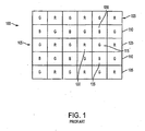
- the Bayer pattern 100 is an array of repeating red (R), green (G), and blue (B) filters causing pixels underneath the filters to be red, blue, and green pixels, respectively.
- red, green and blue pixels are arranged so that alternating red and green pixels are on a first row 105 of an array, and alternating blue and green pixels are on a next row 110. These alternating rows are repeated throughout the array.
- the image sensor is read out, line by line, the pixel sequence for the first line reads GRGRGR etc., and then the alternate line sequence reads BGBGBG etc. This output is called sequential RGB or sRGB.
- sampling rates for all three basic colors are adjusted according to the acuity of the human visual system. That is, green color, to which the human eye is most sensitive and responsive, is sensed with a larger number of sensors, whereas blue and red color, for which the human vision has less resolution, are sensed with a fewer number of sensors. This is why in the Bayer pattern, the green-sensitive elements occur at every other array position, while the red-sensitive elements and the blue-sensitive elements occur at every fourth array position.
- the Bayer patterned filters may be formed over an array 200 of pixel sensors 205.
- an array 200 of pixel sensors 205 is formed on a semiconductor substrate 210.
- Each pixel sensor 205 has a photosensitive element 215, which may be any photon-to-charge converting device, such as a photogate, photoconductor or photodiode.
- the color filter array 220 may be formed over an upper level metal layer 225 in the array 200, separated from the photosensors 215 by various metallization and insulating layers such as an interlevel dielectric layer (ILD) 235 containing insulator metallization patterns and a passivation layer 230.
- the metal layer 225 may be opaque and used to shield the areas of the pixels that are not light sensitive.
- Convex lenses 240 are formed over the color filters 220. In operation, incident light is focused by the lenses 240 through the filters 220 to the photosensitive element 215.
- pixel sensor cell 115 is associated with a green filter, which causes pixel sensor cell 115 to sense green light and produce a signal which represents only green light.
- a value may be interpolated from the neighboring red pixel sensor cells 120 and 125 and the neighboring blue pixel sensor cells 130 and 135, respectively. If demosaicing is not performed correctly, the resulting image may suffer from the inclusion of highly visible color artifacts.
- the value used for a first color is based on a sensed color (i.e., the light sensed by the pixel's sensor 205) and the values for the remaining two colors are based on an interpolated value from the sensed values of corresponding neighboring pixels.
- a sensed color i.e., the light sensed by the pixel's sensor 205
- the values for the remaining two colors are based on an interpolated value from the sensed values of corresponding neighboring pixels.
- Each of the sensed values are representative of the color value at the center of the pixel.
- Each of the interpolated color values are also representative of the value at the center of the pixel.
- the interpolated signal is inherently of a lower quality than the originally sensed signal. For example, an interpolated red color value at the center of a pixel would be different than a sensed red color value for the center of the same pixel.
- Demosaicing methods which typically only reconstruct the missing color components, may result in artifacts such as so-called zipper effects and random color dots. Additionally, there exists a trade off between filtering for noise and the blurring of sharp edges. Interpolating a pixel using the surrounding pixel values tends to blur the image when pixels at an edge are interpolated. Furthermore, this 2 also leads to a decrease in the sharpness of the image at the edges. This is mainly due to the averaging of pixels which are across an edge contained within the image. The demosaicing method averages pixels so that a pixel at an edge does not have the sharpness desired of an edge pixel. Accordingly, there is a desire and need for color plane interpolation that provides improved demosaicing techniques that detect and account for image edges when calculating interpolation values.
- a method and apparatus for color plane interpolation are provided which interpolate the color values of pixels differently depending on an edge direction and whether a pixel is at an edge within an image.
- the use of the edge detection during the interpolation of each of the colors present in the color pattern helps reduce some of the disadvantages of the loss of image sharpness abundant in known demosaicing techniques.
- FIG. 1 is a top-down illustration of a conventional color filter array
- FIG. 2 is a cross-sectional view of a portion of a pixel array having a color filter array
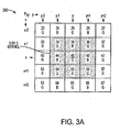
- FIGs. 3A-B are exemplary top views of a five by five pixel kernel used in an exemplary interpolation scheme of the present invention.
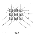
- FIG. 4 is a block diagram of a three by three kernel that is used in accordance with an exemplary embodiment of the invention.
- FIG. 5 is a block diagram of a CMOS imager integrated circuit (IC) having a pixel array constructed according to an exemplary embodiment of the invention
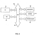
- FIG. 6 is an illustration of a processor system having a CMOS imager according to the present invention.
- FIG. 7 is a flow chart illustrating the process of one embodiment of the present invention.
- pixel refers to a picture element unit cell containing a photosensor and transistors for converting light radiation to an electrical signal.
- a representative pixel is illustrated in the figures and description herein and, typically, fabrication of all pixels in an imager will proceed simultaneously in a similar fashion.
- the following detailed description is, therefore, not to be taken in a limiting sense, and the scope of the present invention is defined by the appended claims.
- CMOS imager in accordance with the present invention is made for the sole purpose of describing just one example of the present invention. It should be readily apparent that the present invention is not limited to CMOS imagers; but also applies to CCD and other images that employ color filters over pixels. Additionally, the current invention is described using a standard three color Bayer pattern. It should be understood that the present invention is not limited to the standard three color Bayer pattern but may be applied to color spaces which use different colors or which use more, or less, than three colors.
- FIGs. 3A , 3B are top-down illustrations of a partial pixel array 300 of an imager in accordance with embodiments of the invention. Specifically, FIGs. 3A , 3B illustrate a five by five kernel (discussed below in more detail) used in the present invention. As previously noted, each pixel, e.g., pixel 23, senses a single color. Accordingly, each green (G) pixel provides a sensed value for green. Similarly, each blue (B) pixel provides a sensed value for blue and each red (R) pixel provides a sensed value for red. For each pixel of a particular color, the values for each of the remaining colors is interpolated to reconstruct the color image.
- the sensed pixel value may also be replaced by an interpolated value. Interpolation of the red, green and blue values eliminate the imbalance resulting from the use of sensed values for one of the colors and interpolated values of the remaining two colors (prevalent in prior art systems).
- the five by five kernel of surrounding pixels is used in the following interpolation calculations, though in many of the interpolation calculations only pixels in the three by three kernel are needed.
- other kernel sizes may also be employed in the invention.
- a three by three interpolated kernel within the five by five kernel, is first defined and color values for the pixel within the kernel are then calculated. Next, an edge direction is determined. Depending on the pixel color and the edge direction, some values of the three by three kernel may be recalculated. The three by three kernel is then used to determine whether an edge is present for the selected pixel. Then, based on whether an edge is present and the pixel color interpolation values are calculated. Different interpolation parameters are applied in the interpolation process based on whether a processed pixel is at an image edge, as well as the sensed color of the pixel.
- step 701 a pixel is selected for processing. Throughout the description representative pixel 45 illustrated in FIGs. 3A , 3B and as the center pixel in FIG. 4 , is used as the exemplary pixel being processed.
- step 703 the three by three kernel surrounding the selected pixel is defined (e.g., pixels 34, 35, 36, 44, 45, 46, 54, 55, and 56 in FIGs. 3A and 3B ).
- step 705 it is determined whether pixel 45 is a sensed green pixel.
- step 707 the green values for the three by three kernel are calculated in accordance with equation set (1) below using actual sensed pixel values from the pixels within the three by three kernel.
- FIG. 4 illustrates the locations within the three by three kernel for the calculated green values g11, g12, g13, g21, g22, g23, g31, g32, g33 for pixels within the three by three kernel.
- the three by three kernel is calculated using the actual values of green pixels 25, 34, 36, 45, 47, 54, 56 and 65 illustrated in FIG. 3A .
- step 709 the three by three kernel is calculated using the values of green pixels 24, 26, 33, 35, 37, 44, 46, 53, 55, 57, 64 and 65 in accordance with equation set (2) below.
- the same kernel values are interpolated using median interpolation of actual sensed values of surrounding green pixels.
- the three by three interpolated kernel is green, in this exemplary embodiment, because as previously noted in a Bayer CFA, the green pixels are most prevalent and influential in the image.
- the values of pixels in the three by three kernel g11, g12, g13, g21, g22, g23, g31, g32, g33, illustrated in FIG. 4 are a calculation of the green values of the pixels in the three by three kernel illustrated in FIGs. 3A and 3B .
- the green kernel will be used during edge detection and in the calculation of the correction terms.
- One of ordinary skill in the art would appreciate that other pixel colors may be used to calculate the three by three interpolated kernel or that the kernel may be of a different size.
- step 711 illustrated in FIG. 7 , the calculated three by three green kernel is used to determine an edge direction.
- the values of four edge directions are calculated in step 711.
- Dashed lines 2, 5, 8 and 11, illustrated in FIG. 4 are the four directions for which edge direction calculations are done. The remaining dashed lines are only exemplary for use in calculating the four edge direction values.
- the edge direction value DIRx is calculated for each of the direction lines 2, 5, 8, and 11.
- the direction having the greatest DIR value is determined to be the edge direction and is determined in step 711.
- step 729 it is determined whether the maximum difference value among the calculated difference values is greater than a predetermined edge threshold value using an equation (7): MAX D 1 ... D 7 > Edge Threshold .
- the edge threshold may be set to be application specific or set based on a user's preferences.
- step 729 If no edge is detected in step 729, it is again determined if processed pixel 45 is green. If processed pixel 45 is green, in step 739 a eighth set (8) of equations is used to calculate the interpolated red, green and blue values of pixel 45.
- step 741 it is determined if processed pixel 45 is blue. If processed 45 is blue, a ninth (9) set of equations is used to calculate the red, green and blue values of pixel 45 in step 747.
- processed pixel 45 is not blue, pixel 45 is red and a tenth (10) set of equations is used to calculate the red, green and blue values of pixel 45 in step 749.
- the interpolation values of the red, green and blue values of pixel 45 are calculated using an eleventh (11) set of equations.
- the values of DELTA blue and DELTA red are calculated based on which direction the edge was determined to be in step 711.
- step 734 If in step 734 it is determined that processed pixel 45 is not green, in step 745 it is determined if the processed pixel 45 is blue. If processed pixel 45 is blue, a twelfth (12) set of equations is equations is used in step 751 to calculate the red, green and blue interpolation values.
- the DELTA correction values for the red and blue pixels are based on the edge direction and the green three by three interpolated kernel.
- the invention provides a new and novel system and method for color plane interpolation, in which interpolated values for green, red and blue are calculated based on not only the sensed values obtained but also whether a processed pixel is at an image edge.
- the imbalance between sensed values and interpolated values is removed by interpolating the values for each of the colors. Further, edge detection and correction terms are utilized to minimize blurring of image edges.
- FIG. 5 illustrates a block diagram of a CMOS imager integrated circuit (IC) 500 having a pixel array 505 containing a plurality of pixels arranged in rows and columns, including a region 510 with, for example, two green pixels (G), one blue pixel (B), and one red pixel (R) arranged in a Bayer pattern.
- the pixels of each row in array 505 are all turned on at the same time by row select lines 515, and the pixels of each column are selectively output by respective column select lines 520.
- the row lines 515 are selectively activated by a row driver 525 in response to row address decoder 530.
- the column select lines 520 are selectively activated by a column selector 535 in response to column address decoder 540.
- the pixel array 505 is operated by the timing and control circuit 545, which controls address decoders 530, 540 for selecting the appropriate row and column lines for pixel signal readout.
- the pixel column signals which typically include a pixel reset signal (V rst ) and a pixel image signal (V sig ), are read by a sample and hold circuit 550 associated with the column selector 535.
- a differential signal (V rst - V sig ) is produced by differential amplifier 555 for each pixel that is amplified and digitized by analog-to-digital converter 570 (ADC).
- ADC analog-to-digital converter 570
- the analog-to-digital converter 570 supplies the digitized pixel signals to an image processor 575, which performs the processing method 700 of the invention.
- image processor 575 can output an image file in a raw format as received from the analog-to-digital converter 570 which can be received and processed in accordance with the invention by a different processor.
- a typical processor system which includes an imager device 605 having a pixel array in which the pixels signals are interpolated according to the present invention is illustrated generally at 600 in FIG. 6 .
- the imager device 605 produces an output image from signals supplied from the pixel array.
- a processor system is exemplary of a system receiving the output of a CMOS imager device. Without being limiting, such a system could include a computer system, camera system, scanner, machine vision system, medical sensor system (such as medical pill sensors), and automotive diagnostic system, and other imaging systems, all of which can utilize the present invention.
- the image processor 575 in the imager device 605 provides a progressed image signal, the invention can performed in the processing system 600.
- a processor system 600 such as a computer system, for example generally comprises a central processing unit (CPU) 610, for example, a microprocessor, that communicates with an input/output (I/O) device 615 over a bus 620.
- the imager device 605 also communicates with the system over bus 620 or other communication link.
- the processor-based system 600 also includes random access memory (RAM) 625, and can include removable memory 630, such as flash memory, which also communicates with the CPU 610 over the bus 620.
- the imaging device 600 may be combined with a processor, such as a CPU, digital signal processor, or microprocessor, with or without memory storage on a single integrated circuit or on a different chip than the processor.
- a program embodying the processing method may be stored on a carrier medium which may include RAM, floppy disk, data transmission, compact disk, etc. and then be executed by an associated processor which receives and processes an image file in accordance with the invention or the processing method may be embodied in a circuit or a combination thereof.
- the invention may be implemented as a plug-in for existing software applications or it may used on its own.
- the invention is not limited to the carrier mediums specified herein and the invention may be implemented using any carrier medium as known in the art.
Landscapes
- Engineering & Computer Science (AREA)
- Multimedia (AREA)
- Signal Processing (AREA)
- Physics & Mathematics (AREA)
- Spectroscopy & Molecular Physics (AREA)
- General Physics & Mathematics (AREA)
- Theoretical Computer Science (AREA)
- Color Television Image Signal Generators (AREA)
- Facsimile Image Signal Circuits (AREA)
- Color Image Communication Systems (AREA)
Claims (25)
- Procédé (700) d'interpolation de plan couleur de pixels d'image, ledit procédé comprenant les étapes suivantes :la sélection d'un pixel en vue de son traitement (701) ;la formation d'un noyau de pixels voisins associés audit pixel sélectionné (703) ;la détermination de quatre valeurs de sens de bord, les quatre valeurs de sens de bord représentant respectivement un sens de bord horizontal, un sens de bord vertical, et les deux sens de bords diagonaux, caractérisé pat :la détermination si ledit pixel sélectionné se trouve ou non au niveau d'un bord dans une image et du sens de ce bord en fonction des valeurs de sens de bords (711) ; etla génération d'une valeur dudit pixel sélectionné pour chaque couleur d'une matrice de couleurs en fonction desdits pixels voisins, de la position ou non dudit pixel sélectionné au niveau dudit bord et du sens dudit bord.
- Procédé selon la revendication 1, comprenant en outre une étape de calcul de valeurs de pixels d'une couleur de ladite matrice de couleurs pour tous les pixels dans ledit noyau et de détermination dudit sens de bord en utilisant lesdites valeurs de pixels de noyau calculées d'une couleur.
- Procédé selon la revendication 2, comprenant en outre le recalcul d'au moins une valeur de pixel dans ledit noyau en fonction dudit sens de bord déterminé.
- Procédé selon la revendication 1, dans lequel ladite matrice de couleurs est une matrice de Bayer.
- Procédé selon la revendication 2, dans lequel ladite une couleur est le vert.
- Procédé selon la revendication 3, dans lequel ladite étape de recalcul de ladite au moins une valeur de noyau est recalculée uniquement si le sens de bord déterminé est horizontal ou vertical.
- Procédé selon la revendication 1, dans lequel ladite étape de détermination si ledit pixel sélectionné se trouve ou non au niveau d'un bord dans une image comprend :le calcul de valeurs de différence entre des paires différentes de pixels d'une même couleur (725, 727) ; etla comparaison de la plus grande valeur de différence à une valeur de seuil prédéterminée (729).
- Procédé selon la revendication 7, dans lequel lesdites paires de pixels peuvent inclure ledit pixel.
- Dispositif imageur couleur comportant une matrice de détection (200) de capteurs de pixels d'image (205), ledit dispositif comprenant :une première pluralité de capteurs de pixels d'image qui sont utilisés pour produire des valeurs détectées d'une première couleur ;une deuxième pluralité de capteurs de pixels d'image qui sont utilisés pour produire des valeurs détectées d'une deuxième couleur ;une troisième pluralité de capteurs de pixels d'image qui sont utilisés pour produire des valeurs détectées d'une troisième couleur ; etun moyen d'interpolation configuré pour :utiliser lesdites valeurs détectées de la première couleur afin de déterminer un premier ensemble de valeurs de pixels d'une pluralité de pixels d'image dans un noyau de pixels, comportant un pixel sélectionné et des pixels voisins, pour ladite première couleur ;déterminer quatre valeurs de sens de bord, les quatre valeurs de sens de bord représentant respectivement un sens de bord horizontal, un sens de bord vertical, et les deux sens de bords diagonaux, caractérisé par :la détermination si ledit pixel sélectionné se trouve ou non au niveau d'un bord dans une image en utilisant ledit premier ensemble de valeurs de pixels ; etle calcul de valeurs d'interpolation desdites première, deuxième et troisième couleurs dudit pixel sélectionné en fonction dudit premier ensemble de valeurs de pixels, desdits pixels voisins et dudit sens de bord déterminé en fonction des valeurs de sens de bord.
- Dispositif imageur couleur selon la revendication 9, dans lequel au moins une valeur dudit noyau de pixels est recalculée en fonction dudit sens de bord avant le calcul desdites valeurs d'interpolation.
- Dispositif imageur couleur selon la revendication 9, dans lequel ledit noyau de couleurs est un noyau de trois pixels sur trois.
- Dispositif imageur couleur selon la revendication 9, dans lequel lesdites quatre valeurs de sens de bord sont calculées comme suit :


et
où S1, S2, S3, S4, S5, S6, S7, S8, S9, S10, S11 et S12 sont calculés comme suit :





et
en utilisant ledit noyau où g11, g12 et g13 sont les valeurs de pixels de la première rangée dudit noyau, g21, g22 et g23 sont les valeurs de pixels de la deuxième rangée dudit noyau et g31, g32, et g33 sont les valeurs de pixels de la troisième rangée du noyau et dans lequel ledit sens de bord est le sens ayant la plus grande valeur. - Dispositif imageur couleur selon la revendication 9, dans lequel ledit bord est détecté en calculant des valeurs de différence de pixels voisins et en comparant une valeur de différence maximum à un seuil de bord.
- Dispositif imageur couleur selon la revendication 13, dans lequel lesdites valeurs de différence sont calculées comme suit quand ledit pixel sélectionné est vert :


et
où Px, y est le pixel sélectionné et le "x" se rapporte à la rangée dans laquelle le pixel est relatif au pixel sélectionné Px, y et "y" se rapporte à la colonne dans laquelle le pixel est relatif au pixel sélectionné Px, y. - Dispositif imageur couleur selon la revendication 13, dans lequel lesdites valeurs de différence sont calculées comme suit quand ledit pixel sélectionné est rouge ou bleu :


et
où Px, y est le pixel sélectionné et le "x" se rapporte à la rangée dans laquelle le pixel est relatif au pixel sélectionné Px, y et "y" se rapporte à la colonne dans laquelle le pixel est relatif au pixel sélectionné Px, y. - Dispositif imageur couleur selon la revendication 11, dans lequel quand ledit pixel est vert, ledit noyau de trois sur trois est calculé comme suit :


et
où Px, y est le pixel sélectionné et le "x" se rapporte à la rangée dans laquelle le pixel est relatif au pixel sélectionné Px, y et "y" se rapporte à la colonne dans laquelle le pixel est relatif au pixel sélectionné Px, y. - Dispositif imageur couleur selon la revendication 11, dans lequel quand ledit pixel est rouge ou bleu, ledit noyau de trois sur trois est calculé comme suit :






et
où Px, y est le pixel sélectionné et le "x" se rapporte à la rangée dans laquelle le pixel est relatif au pixel sélectionné Px, y et "y" se rapporte à la colonne dans laquelle le pixel est relatif au pixel sélectionné Px, y. - Dispositif imageur couleur selon la revendication 9, dans lequel quand ledit pixel est vert et qu'aucun bord n'est présent, lesdites valeurs d'interpolation calculées desdites première, deuxième et troisième couleurs dudit pixel sélectionné sont calculées comme suit :


et
où Px, y est le pixel sélectionné et le "x" se rapporte à la rangée dans laquelle le pixel est relatif au pixel sélectionné Px, y et "y" se rapporte à la colonne dans laquelle le pixel est relatif au pixel sélectionné Px, y. - Dispositif imageur couleur selon la revendication 9, dans lequel quand ledit pixel est bleu et qu'aucun bord n'est présent, lesdites valeurs d'interpolation calculées desdites première, deuxième et troisième couleurs dudit pixel sélectionné sont calculées comme suit :


et
où Px, y est le pixel sélectionné et le "x" se rapporte à la rangée dans laquelle le pixel est relatif au pixel sélectionné Px, y et "y" se rapporte à la colonne dans laquelle le pixel est relatif au pixel sélectionné Px, y. - Dispositif imageur couleur selon la revendication 9, dans lequel quand ledit pixel est rouge et qu'aucun bord n'est présent, lesdites valeurs d'interpolation calculées desdites première, deuxième et troisième couleurs dudit pixel sélectionné sont calculées comme suit :


et
où Px, y est le pixel sélectionné et le "x" se rapporte à la rangée dans laquelle le pixel est relatif au pixel sélectionné Px, y et "y" se rapporte à la colonne dans laquelle le pixel est relatif au pixel sélectionné Px, y. - Dispositif imageur couleur selon la revendication 9, dans lequel quand ledit pixel est vert et qu'un bord est présent, lesdites valeurs d'interpolation calculées desdites première, deuxième et troisième couleurs dudit pixel sélectionné sont calculées comme suit :


et
où g22 et les termes de correction DELTArouge et DELTAbleu sont calculés en fonction desdites valeurs de noyau et où Px, y est le pixel sélectionné et le "x" se rapporte à la rangée dans laquelle le pixel est relatif au pixel sélectionné Px, y et "y" se rapporte à la colonne dans laquelle le pixel est relatif au pixel sélectionné Px, y. - Dispositif imageur couleur selon la revendication 9, dans lequel quand ledit pixel est bleu et qu'un bord est présent, lesdites valeurs d'interpolation calculées desdites première, deuxième et troisième couleurs dudit pixel sélectionné sont calculées comme suit :


et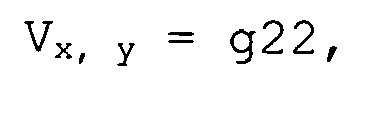
où g22 et le terme de correction DELTArouge sont calculés en fonction desdites valeurs de noyau et où Px, y est le pixel sélectionné et le "x" se rapporte à la rangée dans laquelle le pixel est relatif au pixel sélectionné px, y et "y" se rapporte à la colonne dans laquelle le pixel est relatif au pixel sélectionné px, y. - Dispositif imageur couleur selon la revendication 9, dans lequel quand ledit pixel est rouge et qu'un bord est présent, lesdites valeurs d'interpolation calculées desdites première, deuxième et troisième couleurs dudit pixel sélectionné sont calculées comme suit :


et
où g22 et DELTArouge sont calculés en fonction desdites valeurs de noyau et où Px, y est le pixel sélectionné et le "x" se rapporte à la rangée dans laquelle le pixel est relatif au pixel sélectionné px, y et "y" se rapporte à la colonne dans laquelle le pixel est relatif au pixel sélectionné px, y. - Système de traitement comprenant un dispositif imageur selon la revendication 9.
- Système de traitement selon la revendication 24, dans lequel lesdites première, deuxième et troisième couleurs sont respectivement le vert, le rouge, et le bleu.
Applications Claiming Priority (2)
| Application Number | Priority Date | Filing Date | Title |
|---|---|---|---|
| US11/319,398 US7830426B2 (en) | 2005-12-29 | 2005-12-29 | Method and apparatus providing color interpolation in color filter arrays using edge detection and correction terms |
| PCT/US2006/048200 WO2007078912A1 (fr) | 2005-12-29 | 2006-12-19 | Procede et appareil permettant d'assurer une interpolation de la couleur dans des reseaux de filtre colore par detection des contours et au moyen de termes de correction |
Publications (2)
| Publication Number | Publication Date |
|---|---|
| EP1969558A1 EP1969558A1 (fr) | 2008-09-17 |
| EP1969558B1 true EP1969558B1 (fr) | 2011-08-10 |
Family
ID=37909481
Family Applications (1)
| Application Number | Title | Priority Date | Filing Date |
|---|---|---|---|
| EP06845702A Active EP1969558B1 (fr) | 2005-12-29 | 2006-12-19 | Procede et appareil permettant d'assurer une interpolation de la couleur dans des reseaux de filtre colore par detection des contours et au moyen de termes de correction |
Country Status (8)
| Country | Link |
|---|---|
| US (2) | US7830426B2 (fr) |
| EP (1) | EP1969558B1 (fr) |
| JP (1) | JP4893973B2 (fr) |
| KR (1) | KR101007754B1 (fr) |
| CN (1) | CN101336438B (fr) |
| AT (1) | ATE520100T1 (fr) |
| TW (1) | TWI337499B (fr) |
| WO (1) | WO2007078912A1 (fr) |
Families Citing this family (45)
| Publication number | Priority date | Publication date | Assignee | Title |
|---|---|---|---|---|
| GB2426881B (en) * | 2005-06-01 | 2010-12-29 | Snell & Wilcox Ltd | Method and apparatus for spatial interpolation of colour images |
| US7924483B2 (en) * | 2006-03-06 | 2011-04-12 | Smith Scott T | Fused multi-array color image sensor |
| KR100780932B1 (ko) * | 2006-05-30 | 2007-11-30 | 엠텍비젼 주식회사 | 컬러 보간 방법 및 장치 |
| US8417759B2 (en) * | 2007-04-09 | 2013-04-09 | DigitalOptics Corporation Europe Limited | Efficient implementations of kernel computations |
| US20080260291A1 (en) * | 2007-04-17 | 2008-10-23 | Nokia Corporation | Image downscaling by binning |
| US20090077359A1 (en) * | 2007-09-18 | 2009-03-19 | Hari Chakravarthula | Architecture re-utilizing computational blocks for processing of heterogeneous data streams |
| US20090092338A1 (en) * | 2007-10-05 | 2009-04-09 | Jeffrey Matthew Achong | Method And Apparatus For Determining The Direction of Color Dependency Interpolating In Order To Generate Missing Colors In A Color Filter Array |
| US8270713B2 (en) * | 2007-10-16 | 2012-09-18 | Aptina Imaging Corporation | Method and apparatus providing hardware-efficient demosaicing of image data |
| US8086034B2 (en) | 2008-02-05 | 2011-12-27 | Aptina Imaging Corporation | System and method for reducing color artifacts in digital images |
| JP5076186B2 (ja) * | 2008-10-23 | 2012-11-21 | 株式会社メガチップス | 画像拡大方法 |
| US8073246B2 (en) * | 2008-11-07 | 2011-12-06 | Omnivision Technologies, Inc. | Modifying color and panchromatic channel CFA image |
| US8035698B2 (en) * | 2009-01-21 | 2011-10-11 | Seiko Epson Corporation | Joint automatic demosaicking and white balancing |
| JP5326943B2 (ja) * | 2009-08-31 | 2013-10-30 | ソニー株式会社 | 画像処理装置、および画像処理方法、並びにプログラム |
| US8593483B2 (en) | 2009-10-20 | 2013-11-26 | Apple Inc. | Temporal filtering techniques for image signal processing |
| US8638342B2 (en) | 2009-10-20 | 2014-01-28 | Apple Inc. | System and method for demosaicing image data using weighted gradients |
| US8471932B2 (en) | 2010-09-30 | 2013-06-25 | Apple Inc. | Spatial filtering for image signal processing |
| JP2012239103A (ja) * | 2011-05-13 | 2012-12-06 | Sony Corp | 画像処理装置、および画像処理方法、並びにプログラム |
| TW201305965A (zh) * | 2011-07-18 | 2013-02-01 | Novatek Microelectronics Corp | 影像處理方法 |
| KR101327227B1 (ko) | 2012-02-21 | 2013-11-11 | 중앙대학교 산학협력단 | 영상의 구조를 고려한 노이즈 제거장치 및 방법 |
| US9031319B2 (en) | 2012-05-31 | 2015-05-12 | Apple Inc. | Systems and methods for luma sharpening |
| US8817120B2 (en) | 2012-05-31 | 2014-08-26 | Apple Inc. | Systems and methods for collecting fixed pattern noise statistics of image data |
| US9142012B2 (en) | 2012-05-31 | 2015-09-22 | Apple Inc. | Systems and methods for chroma noise reduction |
| US9014504B2 (en) | 2012-05-31 | 2015-04-21 | Apple Inc. | Systems and methods for highlight recovery in an image signal processor |
| US8953882B2 (en) | 2012-05-31 | 2015-02-10 | Apple Inc. | Systems and methods for determining noise statistics of image data |
| US11089247B2 (en) | 2012-05-31 | 2021-08-10 | Apple Inc. | Systems and method for reducing fixed pattern noise in image data |
| US9077943B2 (en) | 2012-05-31 | 2015-07-07 | Apple Inc. | Local image statistics collection |
| US8872946B2 (en) | 2012-05-31 | 2014-10-28 | Apple Inc. | Systems and methods for raw image processing |
| US9025867B2 (en) | 2012-05-31 | 2015-05-05 | Apple Inc. | Systems and methods for YCC image processing |
| US8917336B2 (en) | 2012-05-31 | 2014-12-23 | Apple Inc. | Image signal processing involving geometric distortion correction |
| US9332239B2 (en) | 2012-05-31 | 2016-05-03 | Apple Inc. | Systems and methods for RGB image processing |
| US9743057B2 (en) | 2012-05-31 | 2017-08-22 | Apple Inc. | Systems and methods for lens shading correction |
| US9105078B2 (en) | 2012-05-31 | 2015-08-11 | Apple Inc. | Systems and methods for local tone mapping |
| CN102938843B (zh) * | 2012-11-22 | 2014-12-03 | 华为技术有限公司 | 图像处理方法、装置以及成像设备 |
| JP2015065270A (ja) * | 2013-09-25 | 2015-04-09 | ソニー株式会社 | 固体撮像装置およびその製造方法、並びに電子機器 |
| JP6415094B2 (ja) | 2014-04-25 | 2018-10-31 | キヤノン株式会社 | 画像処理装置、撮像装置、画像処理方法およびプログラム |
| KR102224742B1 (ko) | 2014-06-10 | 2021-03-09 | 삼성디스플레이 주식회사 | 영상 표시 방법 |
| JP6478641B2 (ja) * | 2015-01-08 | 2019-03-06 | キヤノン株式会社 | 画像処理装置、情報処理方法及びプログラム |
| KR101660447B1 (ko) * | 2015-03-26 | 2016-09-28 | 인천대학교 산학협력단 | 베이어 패턴 컬러 필터 어레이 디모자이킹을 위한 다 방향 가중 보간 방법 |
| US20180288281A1 (en) * | 2016-01-25 | 2018-10-04 | Hewlett-Packard Development Company, L.P. | Interpolating pixel values |
| CN109993693B (zh) * | 2017-12-29 | 2023-04-25 | 澜至电子科技(成都)有限公司 | 用于对图像进行插值的方法和装置 |
| CN111163301B (zh) * | 2018-11-07 | 2021-04-20 | 浙江宇视科技有限公司 | 色彩调整方法、装置及计算机可读存储介质 |
| CN109829852B (zh) * | 2019-01-17 | 2023-04-25 | 浙江大华技术股份有限公司 | 颜色滤波阵列图像处理的方法、装置及存储介质 |
| CN110517189B (zh) * | 2019-08-02 | 2023-03-21 | Oppo广东移动通信有限公司 | 图像处理方法和装置,及存储介质 |
| KR102797187B1 (ko) | 2020-10-23 | 2025-04-18 | 삼성전자주식회사 | 심층 학습 기반의 디모자이킹 방법 및 디모자이킹 장치 |
| KR102462804B1 (ko) * | 2021-06-28 | 2022-11-04 | 주식회사 아이닉스 | 베이어 패턴 이미지에 기반한 렌즈 왜곡 보정 장치 및 그 보정 방법 |
Family Cites Families (15)
| Publication number | Priority date | Publication date | Assignee | Title |
|---|---|---|---|---|
| US3971065A (en) * | 1975-03-05 | 1976-07-20 | Eastman Kodak Company | Color imaging array |
| US5852475A (en) * | 1995-06-06 | 1998-12-22 | Compression Labs, Inc. | Transform artifact reduction process |
| US6181376B1 (en) * | 1997-10-14 | 2001-01-30 | Intel Corporation | Method of determining missing color values for pixels in a color filter array |
| JPH11122626A (ja) * | 1997-10-17 | 1999-04-30 | Nikon Corp | 画像処理方法及び装置並びに画像処理プログラムを記録した記録媒体 |
| US6614474B1 (en) * | 1998-08-27 | 2003-09-02 | Polycom, Inc. | Electronic pan tilt zoom video camera with adaptive edge sharpening filter |
| US6674903B1 (en) * | 1998-10-05 | 2004-01-06 | Agfa-Gevaert | Method for smoothing staircase effect in enlarged low resolution images |
| US6642962B1 (en) * | 1999-09-01 | 2003-11-04 | Neomagic Corp. | Merged pipeline for color interpolation and edge enhancement of digital images |
| US6847396B1 (en) * | 2000-04-26 | 2005-01-25 | Sunplus Technology Co., Ltd. | Interpolation method for producing full color images in using a single-chip color sensor |
| US6707937B1 (en) * | 2000-07-14 | 2004-03-16 | Agilent Technologies, Inc. | Interpolation of edge portions of a digital image |
| US6978050B2 (en) * | 2001-07-18 | 2005-12-20 | Hewlett-Packard Development Company, L.P. | Electronic image color plane reconstruction |
| KR100396898B1 (ko) * | 2001-09-13 | 2003-09-02 | 삼성전자주식회사 | 이미지센서 출력데이터 처리장치 및 처리방법 |
| CN100531332C (zh) * | 2002-03-11 | 2009-08-19 | 皇家飞利浦电子股份有限公司荷 | 图像显示设备 |
| US7542082B2 (en) * | 2004-03-30 | 2009-06-02 | Canon Kabushiki Kaisha | Method and apparatus for correcting a defective pixel |
| KR100587143B1 (ko) * | 2004-05-06 | 2006-06-08 | 매그나칩 반도체 유한회사 | 영상 신호의 에지 검출 방법 |
| JP4333997B2 (ja) * | 2004-08-24 | 2009-09-16 | シャープ株式会社 | 画像処理装置、撮影装置、画像処理方法、画像処理プログラムおよび記録媒体 |
-
2005
- 2005-12-29 US US11/319,398 patent/US7830426B2/en active Active
-
2006
- 2006-12-19 KR KR1020087017803A patent/KR101007754B1/ko active Active
- 2006-12-19 EP EP06845702A patent/EP1969558B1/fr active Active
- 2006-12-19 WO PCT/US2006/048200 patent/WO2007078912A1/fr not_active Ceased
- 2006-12-19 CN CN2006800519591A patent/CN101336438B/zh active Active
- 2006-12-19 JP JP2008548595A patent/JP4893973B2/ja active Active
- 2006-12-19 AT AT06845702T patent/ATE520100T1/de not_active IP Right Cessation
- 2006-12-29 TW TW095149970A patent/TWI337499B/zh active
-
2010
- 2010-09-24 US US12/889,527 patent/US8212900B2/en not_active Expired - Lifetime
Also Published As
| Publication number | Publication date |
|---|---|
| TWI337499B (en) | 2011-02-11 |
| US20110032397A1 (en) | 2011-02-10 |
| KR20080078076A (ko) | 2008-08-26 |
| JP4893973B2 (ja) | 2012-03-07 |
| CN101336438A (zh) | 2008-12-31 |
| KR101007754B1 (ko) | 2011-01-14 |
| US7830426B2 (en) | 2010-11-09 |
| TW200735652A (en) | 2007-09-16 |
| EP1969558A1 (fr) | 2008-09-17 |
| ATE520100T1 (de) | 2011-08-15 |
| WO2007078912A1 (fr) | 2007-07-12 |
| US20070153106A1 (en) | 2007-07-05 |
| CN101336438B (zh) | 2011-11-09 |
| JP2009522864A (ja) | 2009-06-11 |
| US8212900B2 (en) | 2012-07-03 |
Similar Documents
| Publication | Publication Date | Title |
|---|---|---|
| US7830426B2 (en) | Method and apparatus providing color interpolation in color filter arrays using edge detection and correction terms | |
| KR101130023B1 (ko) | 고체 촬상 소자 | |
| US8164651B2 (en) | Concentric exposure sequence for image sensor | |
| CN102197641B (zh) | 改进缺陷色彩及全色滤色器阵列图像 | |
| US8339489B2 (en) | Image photographing apparatus, method and medium with stack-type image sensor, complementary color filter, and white filter | |
| US6781626B1 (en) | System and method of color interpolation | |
| EP3093819B1 (fr) | Appareil d'imagerie, système d'imagerie et procédé de traitement de signal | |
| EP1209903B1 (fr) | Procédé et appareil pour la suppression de bruit d'une image à dynamique étendue échantillonnée de façon éparse | |
| US7876363B2 (en) | Methods, systems and apparatuses for high-quality green imbalance compensation in images | |
| CN101467444A (zh) | 固态图像传感器 | |
| EP0944267A2 (fr) | Un filtre-réseaux colorés dans un appareil de prise de vues en couleurs | |
| US7456881B2 (en) | Method and apparatus for producing Bayer color mosaic interpolation for imagers | |
| WO2008027327A1 (fr) | Procédé, imageur et système fournissant un réseau de filtres colorés de bayer appariés et lecture entrelacée | |
| CN209345244U (zh) | 成像系统和相机模块 | |
| US20070133893A1 (en) | Method and apparatus for image noise reduction | |
| EP1378128B1 (fr) | Procede et appareil de detection et d'interpolation de donnees d'images couleurs | |
| US8400534B2 (en) | Noise reduction methods and systems for imaging devices |
Legal Events
| Date | Code | Title | Description |
|---|---|---|---|
| PUAI | Public reference made under article 153(3) epc to a published international application that has entered the european phase |
Free format text: ORIGINAL CODE: 0009012 |
|
| 17P | Request for examination filed |
Effective date: 20080711 |
|
| AK | Designated contracting states |
Kind code of ref document: A1 Designated state(s): AT BE BG CH CY CZ DE DK EE ES FI FR GB GR HU IE IS IT LI LT LU LV MC NL PL PT RO SE SI SK TR |
|
| RIN1 | Information on inventor provided before grant (corrected) |
Inventor name: SUBBOTIN, IGOR |
|
| 17Q | First examination report despatched |
Effective date: 20090625 |
|
| GRAP | Despatch of communication of intention to grant a patent |
Free format text: ORIGINAL CODE: EPIDOSNIGR1 |
|
| DAX | Request for extension of the european patent (deleted) | ||
| RIN1 | Information on inventor provided before grant (corrected) |
Inventor name: SUBBOTIN, IGOR |
|
| GRAS | Grant fee paid |
Free format text: ORIGINAL CODE: EPIDOSNIGR3 |
|
| GRAA | (expected) grant |
Free format text: ORIGINAL CODE: 0009210 |
|
| AK | Designated contracting states |
Kind code of ref document: B1 Designated state(s): AT BE BG CH CY CZ DE DK EE ES FI FR GB GR HU IE IS IT LI LT LU LV MC NL PL PT RO SE SI SK TR |
|
| REG | Reference to a national code |
Ref country code: GB Ref legal event code: FG4D |
|
| REG | Reference to a national code |
Ref country code: CH Ref legal event code: EP |
|
| REG | Reference to a national code |
Ref country code: IE Ref legal event code: FG4D |
|
| REG | Reference to a national code |
Ref country code: DE Ref legal event code: R096 Ref document number: 602006023765 Country of ref document: DE Effective date: 20111027 |
|
| REG | Reference to a national code |
Ref country code: NL Ref legal event code: VDEP Effective date: 20110810 |
|
| LTIE | Lt: invalidation of european patent or patent extension |
Effective date: 20110810 |
|
| PG25 | Lapsed in a contracting state [announced via postgrant information from national office to epo] |
Ref country code: SE Free format text: LAPSE BECAUSE OF FAILURE TO SUBMIT A TRANSLATION OF THE DESCRIPTION OR TO PAY THE FEE WITHIN THE PRESCRIBED TIME-LIMIT Effective date: 20110810 Ref country code: IS Free format text: LAPSE BECAUSE OF FAILURE TO SUBMIT A TRANSLATION OF THE DESCRIPTION OR TO PAY THE FEE WITHIN THE PRESCRIBED TIME-LIMIT Effective date: 20111210 Ref country code: PT Free format text: LAPSE BECAUSE OF FAILURE TO SUBMIT A TRANSLATION OF THE DESCRIPTION OR TO PAY THE FEE WITHIN THE PRESCRIBED TIME-LIMIT Effective date: 20111212 Ref country code: FI Free format text: LAPSE BECAUSE OF FAILURE TO SUBMIT A TRANSLATION OF THE DESCRIPTION OR TO PAY THE FEE WITHIN THE PRESCRIBED TIME-LIMIT Effective date: 20110810 Ref country code: LT Free format text: LAPSE BECAUSE OF FAILURE TO SUBMIT A TRANSLATION OF THE DESCRIPTION OR TO PAY THE FEE WITHIN THE PRESCRIBED TIME-LIMIT Effective date: 20110810 Ref country code: NL Free format text: LAPSE BECAUSE OF FAILURE TO SUBMIT A TRANSLATION OF THE DESCRIPTION OR TO PAY THE FEE WITHIN THE PRESCRIBED TIME-LIMIT Effective date: 20110810 |
|
| REG | Reference to a national code |
Ref country code: AT Ref legal event code: MK05 Ref document number: 520100 Country of ref document: AT Kind code of ref document: T Effective date: 20110810 |
|
| PG25 | Lapsed in a contracting state [announced via postgrant information from national office to epo] |
Ref country code: LV Free format text: LAPSE BECAUSE OF FAILURE TO SUBMIT A TRANSLATION OF THE DESCRIPTION OR TO PAY THE FEE WITHIN THE PRESCRIBED TIME-LIMIT Effective date: 20110810 Ref country code: PL Free format text: LAPSE BECAUSE OF FAILURE TO SUBMIT A TRANSLATION OF THE DESCRIPTION OR TO PAY THE FEE WITHIN THE PRESCRIBED TIME-LIMIT Effective date: 20110810 Ref country code: AT Free format text: LAPSE BECAUSE OF FAILURE TO SUBMIT A TRANSLATION OF THE DESCRIPTION OR TO PAY THE FEE WITHIN THE PRESCRIBED TIME-LIMIT Effective date: 20110810 Ref country code: SI Free format text: LAPSE BECAUSE OF FAILURE TO SUBMIT A TRANSLATION OF THE DESCRIPTION OR TO PAY THE FEE WITHIN THE PRESCRIBED TIME-LIMIT Effective date: 20110810 Ref country code: CY Free format text: LAPSE BECAUSE OF FAILURE TO SUBMIT A TRANSLATION OF THE DESCRIPTION OR TO PAY THE FEE WITHIN THE PRESCRIBED TIME-LIMIT Effective date: 20110810 Ref country code: GR Free format text: LAPSE BECAUSE OF FAILURE TO SUBMIT A TRANSLATION OF THE DESCRIPTION OR TO PAY THE FEE WITHIN THE PRESCRIBED TIME-LIMIT Effective date: 20111111 |
|
| PG25 | Lapsed in a contracting state [announced via postgrant information from national office to epo] |
Ref country code: BE Free format text: LAPSE BECAUSE OF FAILURE TO SUBMIT A TRANSLATION OF THE DESCRIPTION OR TO PAY THE FEE WITHIN THE PRESCRIBED TIME-LIMIT Effective date: 20110810 |
|
| PG25 | Lapsed in a contracting state [announced via postgrant information from national office to epo] |
Ref country code: SK Free format text: LAPSE BECAUSE OF FAILURE TO SUBMIT A TRANSLATION OF THE DESCRIPTION OR TO PAY THE FEE WITHIN THE PRESCRIBED TIME-LIMIT Effective date: 20110810 Ref country code: CZ Free format text: LAPSE BECAUSE OF FAILURE TO SUBMIT A TRANSLATION OF THE DESCRIPTION OR TO PAY THE FEE WITHIN THE PRESCRIBED TIME-LIMIT Effective date: 20110810 |
|
| PG25 | Lapsed in a contracting state [announced via postgrant information from national office to epo] |
Ref country code: IT Free format text: LAPSE BECAUSE OF FAILURE TO SUBMIT A TRANSLATION OF THE DESCRIPTION OR TO PAY THE FEE WITHIN THE PRESCRIBED TIME-LIMIT Effective date: 20110810 Ref country code: RO Free format text: LAPSE BECAUSE OF FAILURE TO SUBMIT A TRANSLATION OF THE DESCRIPTION OR TO PAY THE FEE WITHIN THE PRESCRIBED TIME-LIMIT Effective date: 20110810 Ref country code: EE Free format text: LAPSE BECAUSE OF FAILURE TO SUBMIT A TRANSLATION OF THE DESCRIPTION OR TO PAY THE FEE WITHIN THE PRESCRIBED TIME-LIMIT Effective date: 20110810 |
|
| PLBE | No opposition filed within time limit |
Free format text: ORIGINAL CODE: 0009261 |
|
| STAA | Information on the status of an ep patent application or granted ep patent |
Free format text: STATUS: NO OPPOSITION FILED WITHIN TIME LIMIT |
|
| PG25 | Lapsed in a contracting state [announced via postgrant information from national office to epo] |
Ref country code: DK Free format text: LAPSE BECAUSE OF FAILURE TO SUBMIT A TRANSLATION OF THE DESCRIPTION OR TO PAY THE FEE WITHIN THE PRESCRIBED TIME-LIMIT Effective date: 20110810 |
|
| 26N | No opposition filed |
Effective date: 20120511 |
|
| PG25 | Lapsed in a contracting state [announced via postgrant information from national office to epo] |
Ref country code: MC Free format text: LAPSE BECAUSE OF NON-PAYMENT OF DUE FEES Effective date: 20111231 |
|
| REG | Reference to a national code |
Ref country code: CH Ref legal event code: PL |
|
| GBPC | Gb: european patent ceased through non-payment of renewal fee |
Effective date: 20111219 |
|
| REG | Reference to a national code |
Ref country code: DE Ref legal event code: R097 Ref document number: 602006023765 Country of ref document: DE Effective date: 20120511 |
|
| REG | Reference to a national code |
Ref country code: FR Ref legal event code: ST Effective date: 20120831 |
|
| REG | Reference to a national code |
Ref country code: IE Ref legal event code: MM4A |
|
| PG25 | Lapsed in a contracting state [announced via postgrant information from national office to epo] |
Ref country code: CH Free format text: LAPSE BECAUSE OF NON-PAYMENT OF DUE FEES Effective date: 20111231 Ref country code: LI Free format text: LAPSE BECAUSE OF NON-PAYMENT OF DUE FEES Effective date: 20111231 Ref country code: IE Free format text: LAPSE BECAUSE OF NON-PAYMENT OF DUE FEES Effective date: 20111219 Ref country code: GB Free format text: LAPSE BECAUSE OF NON-PAYMENT OF DUE FEES Effective date: 20111219 |
|
| PG25 | Lapsed in a contracting state [announced via postgrant information from national office to epo] |
Ref country code: FR Free format text: LAPSE BECAUSE OF NON-PAYMENT OF DUE FEES Effective date: 20120102 |
|
| PG25 | Lapsed in a contracting state [announced via postgrant information from national office to epo] |
Ref country code: LU Free format text: LAPSE BECAUSE OF NON-PAYMENT OF DUE FEES Effective date: 20111219 |
|
| PG25 | Lapsed in a contracting state [announced via postgrant information from national office to epo] |
Ref country code: BG Free format text: LAPSE BECAUSE OF FAILURE TO SUBMIT A TRANSLATION OF THE DESCRIPTION OR TO PAY THE FEE WITHIN THE PRESCRIBED TIME-LIMIT Effective date: 20111110 |
|
| PG25 | Lapsed in a contracting state [announced via postgrant information from national office to epo] |
Ref country code: TR Free format text: LAPSE BECAUSE OF FAILURE TO SUBMIT A TRANSLATION OF THE DESCRIPTION OR TO PAY THE FEE WITHIN THE PRESCRIBED TIME-LIMIT Effective date: 20110810 |
|
| PG25 | Lapsed in a contracting state [announced via postgrant information from national office to epo] |
Ref country code: HU Free format text: LAPSE BECAUSE OF FAILURE TO SUBMIT A TRANSLATION OF THE DESCRIPTION OR TO PAY THE FEE WITHIN THE PRESCRIBED TIME-LIMIT Effective date: 20110810 Ref country code: ES Free format text: LAPSE BECAUSE OF FAILURE TO SUBMIT A TRANSLATION OF THE DESCRIPTION OR TO PAY THE FEE WITHIN THE PRESCRIBED TIME-LIMIT Effective date: 20111121 |
|
| PGFP | Annual fee paid to national office [announced via postgrant information from national office to epo] |
Ref country code: DE Payment date: 20251229 Year of fee payment: 20 |