EP1969573B1 - Persönliche warnvorrichtung - Google Patents
Persönliche warnvorrichtung Download PDFInfo
- Publication number
- EP1969573B1 EP1969573B1 EP06831502A EP06831502A EP1969573B1 EP 1969573 B1 EP1969573 B1 EP 1969573B1 EP 06831502 A EP06831502 A EP 06831502A EP 06831502 A EP06831502 A EP 06831502A EP 1969573 B1 EP1969573 B1 EP 1969573B1
- Authority
- EP
- European Patent Office
- Prior art keywords
- alarm
- unit
- evaluation module
- communication means
- detector
- Prior art date
- Legal status (The legal status is an assumption and is not a legal conclusion. Google has not performed a legal analysis and makes no representation as to the accuracy of the status listed.)
- Not-in-force
Links
Images

Classifications
-
- G—PHYSICS
- G08—SIGNALLING
- G08B—SIGNALLING SYSTEMS, e.g. PERSONAL CALLING SYSTEMS; ORDER TELEGRAPHS; ALARM SYSTEMS
- G08B21/00—Alarms responsive to a single specified undesired or abnormal condition and not otherwise provided for
- G08B21/02—Alarms for ensuring the safety of persons
- G08B21/04—Alarms for ensuring the safety of persons responsive to non-activity, e.g. of elderly persons
-
- A—HUMAN NECESSITIES
- A61—MEDICAL OR VETERINARY SCIENCE; HYGIENE
- A61B—DIAGNOSIS; SURGERY; IDENTIFICATION
- A61B5/00—Measuring for diagnostic purposes; Identification of persons
- A61B5/103—Measuring devices for testing the shape, pattern, colour, size or movement of the body or parts thereof, for diagnostic purposes
- A61B5/11—Measuring movement of the entire body or parts thereof, e.g. head or hand tremor or mobility of a limb
-
- A—HUMAN NECESSITIES
- A61—MEDICAL OR VETERINARY SCIENCE; HYGIENE
- A61B—DIAGNOSIS; SURGERY; IDENTIFICATION
- A61B5/00—Measuring for diagnostic purposes; Identification of persons
- A61B5/74—Details of notification to user or communication with user or patient; User input means
- A61B5/746—Alarms related to a physiological condition, e.g. details of setting alarm thresholds or avoiding false alarms
-
- G—PHYSICS
- G08—SIGNALLING
- G08B—SIGNALLING SYSTEMS, e.g. PERSONAL CALLING SYSTEMS; ORDER TELEGRAPHS; ALARM SYSTEMS
- G08B21/00—Alarms responsive to a single specified undesired or abnormal condition and not otherwise provided for
- G08B21/02—Alarms for ensuring the safety of persons
- G08B21/0202—Child monitoring systems using a transmitter-receiver system carried by the parent and the child
- G08B21/0205—Specific application combined with child monitoring using a transmitter-receiver system
- G08B21/0208—Combination with audio or video communication, e.g. combination with "baby phone" function
-
- G—PHYSICS
- G08—SIGNALLING
- G08B—SIGNALLING SYSTEMS, e.g. PERSONAL CALLING SYSTEMS; ORDER TELEGRAPHS; ALARM SYSTEMS
- G08B21/00—Alarms responsive to a single specified undesired or abnormal condition and not otherwise provided for
- G08B21/02—Alarms for ensuring the safety of persons
- G08B21/0202—Child monitoring systems using a transmitter-receiver system carried by the parent and the child
- G08B21/0205—Specific application combined with child monitoring using a transmitter-receiver system
- G08B21/0211—Combination with medical sensor, e.g. for measuring heart rate, temperature
-
- A—HUMAN NECESSITIES
- A61—MEDICAL OR VETERINARY SCIENCE; HYGIENE
- A61B—DIAGNOSIS; SURGERY; IDENTIFICATION
- A61B2503/00—Evaluating a particular growth phase or type of persons or animals
- A61B2503/04—Babies, e.g. for SIDS detection
-
- A—HUMAN NECESSITIES
- A61—MEDICAL OR VETERINARY SCIENCE; HYGIENE
- A61B—DIAGNOSIS; SURGERY; IDENTIFICATION
- A61B5/00—Measuring for diagnostic purposes; Identification of persons
- A61B5/01—Measuring temperature of body parts ; Diagnostic temperature sensing, e.g. for malignant or inflamed tissue
Definitions
- the present invention relates to a personal warning apparatus.
- the present invention relates to an apparatus and method for detecting and preventing the onset of Sudden Infant Death Syndrome.
- the present invention also relates to an apparatus and method for detecting and preventing local environmental conditions associated with Sudden Infant Death Syndrome.
- SIDS Sudden Infant Death Syndrome
- cot death is known to primarily affect infants aged between 3 and 9 months. SIDS occurs unexpectedly and quickly to apparently healthy infants, usually during periods of sleep. There remains some debate as to the causative factors in SIDS, although it is established that ensuring that the infant's breathing remains unobstructed can help to reduce the risk. In addition, it has been proposed that preventing the infant from becoming too hot, and ensuring that the infant sleeps on its back, can help to prevent the risk of SIDS.
- SIDS detection systems use detectors that sense movement of the infant.
- many of these detection systems are triggered by minor movements or when the infant stops moving for only a short period of time, creating many false alarms.
- several of these motion detectors comprise a single unit which is attached to the infant. These motion detection units have no fixed point of reference and are therefore more susceptible to false alarms.
- SIDS systems for detecting SIDS measure the breathing pattern, the temperature, the heartbeat or other vital signs of the infant (some of these devices are known as apnea alarms). However, as infants' heartbeats and breathing patterns are often irregular, such devices can generate false alarms.
- US-B1-6975230 discloses a personal warning apparatus according to the preamble of claim 1.
- SIDS detection systems are prone to causing false alarms, and provide no way of preventing the initial onset of SIDS. It is of particular importance to develop a SIDS detection system that does not produce false alarms, as these can prove stressful and time consuming for the infant's carer. Moreover, numerous false alarms lessen the impact of the alarm on the carer, such that the carer is more likely to inadvertently neglect a genuine alarm. In addition several prior art systems, such as apnea alarms, detect SIDS rather than the causative factors. As such, these alarms provide no way of pre-empting or preventing SIDS.
- a further object of the invention is to provide an apparatus and method for detecting the onset of SIDS.
- a still further object of the invention is to provide an apparatus and method for preventing the onset of SIDS.
- a personal warning apparatus comprising at least one relative motion detector adapted to be positioned on or around the body of an individual, an evaluation module having a predetermined activation threshold, and at least one communication means, the at least one relative motion detector being operatively linked to the evaluation module, and the evaluation module being operatively linked to the at least one communication means, wherein the evaluation module responsive to an evaluation is able to send an alarm signal to the at least one communication means, wherein the relative motion detector is adapted to detect lateral movement where lateral movement is in the direction of the longest axis of the individual's body.
- the evaluation module is adapted to sense motion indicative of the onset of Sudden Infant Death Syndrome.
- the evaluation module can be adapted to activate the at least one communication means on sensing conditions associated with the onset of Sudden Infant Death Syndrome.
- the evaluation module can be a suitably programmed processor.
- the processor can be configured to evaluate detected motion.
- the processor is a microprocessor.
- the processor is an application specific integrated circuit.
- the apparatus further comprises a detector unit adapted to be positioned on or around the body of an individual.
- the apparatus further comprises an alarm unit remote from the detector unit, the detector unit being operatively connected to the alarm unit.
- the apparatus further comprises a relay unit remote from the alarm unit and the detector unit, the detector unit being operatively connected to the relay unit, and the relay unit being operatively connected to the alarm unit.
- the detector unit comprises the at least one relative motion detector, the evaluation module and at least one communication means.
- the detector unit comprises the at least one relative motion detector and at least one communication means
- the alarm unit comprises at least one communication means, the evaluation module and an alarm, the evaluation module being operatively connected to the alarm.
- the detector unit comprises the at least one relative motion detector and at least one communication means
- the relay unit comprises at least one communication means and the evaluation module
- the alarm unit comprises at least one communication means and an alarm, the at least one communication means in the alarm unit being operatively connected to the alarm.
- the predetermined activation threshold is adjustable.
- the relative motion detection means can be adapted to further detect rotational movement, with respect to the longest axis of the individual's body. Therefore, this can be used to monitor whether the infant has moved onto their side.
- the relative motion detection means can be adapted to further detect vertical movement. When an individual is lying down the vertical movement is with respect to the shortest axis of their body. Therefore, this can be used to monitor the individual's breathing.
- the SIDS prevention and detection apparatus is generally depicted at 101 and is comprised of a detector unit 112, a signal repeater or relay unit 113 and alarm unit 103.
- the detector unit 112 contains a radio-frequency transmitter microchip (not shown) and communicates with the relay unit 113 using radio frequency signals.
- the detector unit 112 contains a triaxial accelerometer (not shown) which measures rotational, vertical and lateral movement.
- the detector unit 112 is encased in a liquid resistant pouch (not shown). The pouch is secured to the chest of an infant 109, at rest in a cot 110.
- the detector unit 112 also contains a temperature sensor (not shown) to monitor the infant's temperature.
- the relay unit 113 contains a radio-frequency transceiver microchip (not shown) and communicates with the alarm unit 103, which contains a radio-frequency receiver (not shown), using radio-frequency signals.
- the relay unit also contains a microprocessor which acts as an evaluation module. The microprocessor evaluates the accelerometer readings and determines whether or not an alarm should be generated. If an accelerometer reading is evaluated as high risk, the microprocessor sends an alarm signal to the radio-frequency transceiver microchip which communicates with the alarm unit 103, which in turn generates an alarm.
- the evaluation module can be a suitably programmed processor, microprocessor or application specific integrated circuit, configured to evaluate detected motion and/or temperature.
- the evaluation module is responsive to the evaluation performed. If it concludes that a signal, or set of signals, is associated with risk to the individual it will send an alarm signal, by way of an electrical signal, to the radio-frequency transceiver. The radio frequency transceiver will transmit a signal to the alarm unit which will then raise an alarm.
- the evaluation module is programmable and adjustable, it can be set to have predetermined movement and/or temperature thresholds, which mitigates the generation of false alarms. These thresholds are activation thresholds beyond which the evaluation module will conclude that the infant is at risk.
- the evaluation module can be programmed such that it activates the radio-frequency transceiver, and generates an alarm, on sensing movement and/or temperature conditions associated with the onset of SIDS.
- the components of the detector unit are linked by way of a printed circuit board and the detector unit is powered by a battery.
- the components of the relay unit are also linked using a printed circuit board, and the relay unit is mains electricity powered.
- the components of the alarm unit are linked using a printed circuit board and the alarm unit is mains electricity powered.
- the detector unit, relay unit and alarm unit are linked by radio-frequency transmitters/receivers or transceivers and thus are operatively connected.
- the evaluation module is adapted to be sensitive to motion indicative of the onset of Sudden Infant Death Syndrome.
- the detector unit can be removed from the pouch so that the pouch can be washed.
- the liquid resistant material prevents the ingress of liquid into the pouch and therefore protects the detector and transmitter equipment.
- the pouch containing the detector unit is secured against the infant's chest using an adjustable strap.
- the temperature sensor is located in the pouch.
- the apparatus can contain one or more temperature sensors that measure one or both of the infant's temperature and the ambient temperature.
- the detector can be secured against the infant's chest by any suitable means, including for example a harness or hook and loop fasteners.
- the detector unit is placed in a pouch in a baby vest comprising wicking fabric, a padded chest area and hook and loop fastenings. The detector unit can be removed from the infant's clothing for washing.
- the detector unit is integral to the infant's clothing.
- the detector unit communicates the movements of the infant with the relay unit using small, low-powered digital radio transceivers.
- the same technology is used to communicate between the relay unit and the alarm unit.
- the detector unit communicates directly with the alarm unit, and there is no relay unit present.
- the detector unit also comprises the evaluation module which works in the normal way, sending an alarm signal to the alarm unit in the event of a high risk condition being assessed.
- the evaluation module is placed in the alarm unit rather then the detector unit. The detector unit is in constant communication with the alarm unit. If the evaluation module detects high risk conditions an alarm is generated.
- the detector unit further comprises the evaluation module and an alarm, which acts as a communication means.
- the detector unit it is not necessary for the detector unit to contain a radio-frequency transceiver, although it may optionally do so.
- the detector unit may act alone to detect, evaluate a high risk condition, and create an audible and/or visible alarm.
- Accelerometer devices measure the acceleration and therefore movement in one or more directions.
- one triaxial accelerometer capable of measuring in all three x, y and z axes is used.
- two biaxial accelerometers both measuring in two axes could instead be used, as could three uniaxial accelerometers.
- Monitoring movement in one axis confirms that the infant is breathing. Detecting when the infant moves onto its side is possible by monitoring movement in another axis. According to the invention, significant movement in the remaining axis detects when the infant moves up or down the cot, possibly under their blanket.
- the accelerometer acts as a relative motion detector and the radio-frequency transmitters/receivers in the detector unit, the relay unit, and the alarm unit, act as communication means.
- the accelerometer When the accelerometer detects conditions associated with the onset of SIDS, it sends an electrical signal to the microprocessor which acts as an evaluation module. If the evaluation module senses that the infant is at risk, it will send an electrical signal to the radio-frequency transmitter which in turn transmits a radio-frequency signal to the relay unit which acts as an intermediate transceiver unit. The relay unit transmits a radio-frequency signal to the alarm unit which acts as a remote alert generating means, and the alarm unit generates an audible and/or visible alarm to indicate to a carer that the infant is in a high risk state.
- the accelerometer can detect rotational movement.
- the rotational movement is with respect to the longest axis of an infant's body. That is, with respect to the infant's height. Therefore, this can be used to monitor whether the infant has moved onto their side.
- the rotational movement threshold can be set to between 30° and 45°.
- One way of performing this measurement is to measure the acceleration readings on three separate axes to determine their orientation.
- the accelerometers are effectively measuring an effect of gravity, an axis in line with the ground will give a reading of g.
- the same axis oriented at 45° will give a reading of 0.5g.
- the orientation of the infant can be detected.
- the accelerometer can also detect vertical movement. When an infant is lying down the vertical movement is with respect to the shortest axis of its body. This can be used to monitor the infant's breathing by, for example, averaging a number of acceleration readings (generated by the movement of the infant's chest,'i.e. breathing) and determining if the readings have varied by a particular threshold amount. If the readings do not vary by this amount, the device detects that the infant has stopped breathing.
- the accelerometer detects lateral movement.
- the lateral movement is in the direction of the longest axis of the infant's body. That is with respect to the infant's height. This detection requires the use of high accuracy, fast sampling and low noise.
- the accelerometer provides a measure of the acceleration at a particular sampling instant and thus is used to indirectly measure distance moved in a particular direction. Therefore, this is used to monitor whether the infant has slid underneath any blankets or bed clothing.
- An advantage of the present invention is that the evaluation module used is adjusted to have predetermined activation thresholds, i.e., varying the sensitivity levels.
- the thresholds can be preset during manufacture in accordance to the average, safe movements of an infant during sleep.
- the thresholds can be adjusted by the infant's carer in accordance with individual sleeping habits. This requires apparatus with which the carer can make the necessary adjustments. For example, using suitable software and an existing computer the thresholds can be adjusted and the infant monitored. The same software can be used to display the temperature of the infant and to raise an alarm.
- the thresholds of the evaluation unit can be adjusted using dials or the like attached to the detector unit, the relay unit and/or the alarm unit. Such adjustments can be made manually and without the requirement for a personal computer.
- an infant's breathing is more likely to be irregular or shallow, and thus it is useful to adjust the sensitivity of the evaluation of the accelerometer that monitors breathing.
- the alarm can be activated via a radio-frequency transceiver or can be activated directly by the microprocessor.
- the microprocessor has preset and optionally programmable thresholds associated with the movement of the accelerometers. These thresholds are selected to mitigate the generation of false alarms.
- the movement of the infant may be partially restricted using, for example, a sleeping sack.
- the infant's temperature and/or ambient temperature may be monitored by temperature sensors and optionally evaluated by the microprocessor.
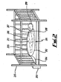
- Figure 2 is a representation of a SIDS alarm apparatus in accordance with an example.
- the SIDS prevention and detection apparatus is generally depicted at 201 and is comprised of a sack 202 and an alarm 203.
- the sack 202 is connected to the alarm 203 via wiring 204. Further wiring (not shown) is encased in a removable conduit 205 which slots into a channel 206 in the sack 202.
- the sack 202 comprises a magnetic switch 207 that is associated with a magnet 208 which is attached to an infant 209 at rest in a cot 210.
- the sack 202 further comprises a temperature sensor 211 for monitoring the infant's temperature.
- the temperature sensor 211 and the magnetic switch 207 are connected to the wiring (not shown) encased in the removable conduit 205.
- the removable conduit 205 provides that all wiring for the alarm 203, the magnetic switch 207 and the temperature sensor 211 is isolated from the infant 209. This ensures the safety of the infant 209 and makes the sack 202 more comfortable for the infant 209 to sleep in. Consequently, the infant 209 is less restless during seep.
- the removable conduit 205 is made from a liquid resistant material to prevent ingress of liquids.
- the removable conduit 205 can be separated from the sack 202, which is particularly useful for the purposes of washing the sack 202. In this example the removable conduit 205 attaches to the channel 206 in the sack 205 by way of a hook and loop fastening system.
- the magnetic switch and associated magnet act as a relative motion detector with an activation threshold that can be predetermined.
- This predetermined activation threshold can be preset or may be adjustable such that a user can set the threshold to their desired level.
- the wiring is integral to the sack and does not run in a removable channel.
- the wiring may still be removed from the sack for the purposes of washing or otherwise.
- the sack may itself provide a degree of water resistance.
- the alarm 203 is connected to the sack 202 via wiring 204 and the sack 202 contains further wiring (not shown) for the temperature sensor 211 and the magnetic switch 207.
- the magnetic switch 207 is fixed in position, stitched into the lining of the sack 202.
- the wiring is replaced by remote transceivers (such as radio frequency transmitters and radio frequency receivers) such that the temperature sensor and the magnetic switch can communicate wirelessly with the alarm.
- remote transceivers such as radio frequency transmitters and radio frequency receivers
- the alarm 203 is an audible and visual alarm which is attached to the cot 210.
- the apparatus communicates with a remote device using means such as radio frequency communication, such that a remote alarm is triggered.
- the remote alarm may be placed next to a carer who is remote from the infant.
- the infant 209 in use the infant 209 is fitted with a magnet 208 on its chest and is placed on its back in the sack 202.
- the sack 202 fits securely around the infant 209 such that minor movements are not constrained, but such that larger movements, for example turning in the sack 202 or sliding inside the sack 202, are prevented. This affords the infant 209 a more comfortable and safer sleeping environment.
- the magnetic switch 207 is adjusted to a predetermined activation threshold such that if the infant 209 moves as part of the normal sleeping process the magnet 208 and magnetic switch 207 remain associated and the magnetic switch 207 is not triggered. However, should the sack 202 fail to constrain the infant 209 and allow the infant 209 to move into a "high risk" position (i.e. if the infant 209 slides inside the sack 202 or turns onto its front), the association between the magnet 208 and the magnetic switch 207 is broken, triggering the alarm 203.
- the predetermined activation threshold can be adjusted. In an alternative example, the predetermined activation threshold is not adjustable.
- the magnetic switch 207 and magnet 208 remain associated when they stay within a certain distance of each other as set by the predetermined activation threshold. That is, the two devices will tolerate a certain degree of relative movement without becoming dissociated. As long as the magnetic switch 207 and the magnet 208 are associated, the magnetic switch 207 will not be activated and the alarm 203 will not be triggered. This affords the present apparatus a degree of flexibility in that the infant 209 may make "safe" movements without triggering the alarm 203. Therefore, the present apparatus prevents false alarms from occurring.
- the magnetic switch and the magnet act as a relative motion sensor that has a degree of tolerance to minor movements.
- the temperature sensor 211 affixed to the sack 202 continuously monitors the temperature of the infant 209. If the temperature deviates from the normal accepted temperature range, the alarm 203 is triggered.
- the alarm 203 may be set to produce a different type of alert depending on whether the temperature sensor 211 or the magnetic switch 207 triggers the alarm 203.
- the alarm 203 may be an audible alert of different pitch for the temperature sensor 211 and the magnetic switch 207.
- the temperature sensor is attached to the infant's abdomen. If the infant's temperature deviates out with the normal accepted temperature range, the temperature sensor will trigger the alarm.
- the temperature sensor can be adapted to be positioned on or around the infant or their clothing.
- An advantage of the present invention is that it detects any movement by an infant into a high risk position. As such, the alarm is triggered before the infant stops breathing and before SIDS occurs. That is to say, the invention detects high risk environmental conditions associated with the onset of SIDS (by means of both the movement and the temperature sensor) rather than SIDS. Therefore, the present invention pre-empts SIDS and can allow a carer to attend to an infant in a high risk environment, before the infant stops breathing, increasing the chances of preventing SIDS.
- Prior art SIDS alarms serve only to inform a carer that SIDS has occurred. As such, they do not afford the carer the opportunity to intervene, so that they might prevent SIDS from occurring. Furthermore, existing SIDS alarms do not combine a SIDS warning system with an apparatus for preventing an infant from adopting wan orientation associated with a higher risk of SIDS. In addition, existing SIDS alarms are prone to false alarms, which detract from their impact in the event of a genuine SIDS incident.
Landscapes
- Health & Medical Sciences (AREA)
- General Health & Medical Sciences (AREA)
- Life Sciences & Earth Sciences (AREA)
- Physics & Mathematics (AREA)
- Child & Adolescent Psychology (AREA)
- Heart & Thoracic Surgery (AREA)
- Business, Economics & Management (AREA)
- Emergency Management (AREA)
- General Physics & Mathematics (AREA)
- Engineering & Computer Science (AREA)
- Molecular Biology (AREA)
- Veterinary Medicine (AREA)
- Pathology (AREA)
- Physiology (AREA)
- Biomedical Technology (AREA)
- Medical Informatics (AREA)
- Biophysics (AREA)
- Surgery (AREA)
- Animal Behavior & Ethology (AREA)
- Public Health (AREA)
- Gerontology & Geriatric Medicine (AREA)
- Cardiology (AREA)
- Dentistry (AREA)
- Oral & Maxillofacial Surgery (AREA)
- Multimedia (AREA)
- Measuring And Recording Apparatus For Diagnosis (AREA)
- Measurement Of The Respiration, Hearing Ability, Form, And Blood Characteristics Of Living Organisms (AREA)
- Burglar Alarm Systems (AREA)
- Emergency Alarm Devices (AREA)
- Alarm Systems (AREA)
- Telephone Function (AREA)
- Measuring Pulse, Heart Rate, Blood Pressure Or Blood Flow (AREA)
Claims (15)
- Eine persönliche Warnvorrichtung (101), die mindestens einen Detektor für relative Bewegung beinhaltet, der angepasst ist, um auf oder um den Körper einer Einzelperson positioniert zu werden, ein Evaluierungsmodul, das eine vorbestimmte Aktivierungsschwelle aufweist, und mindestens ein Kommunikationsmittel, wobei der mindestens eine Detektor für relative Bewegung operativ mit dem Evaluierungsmodul verknüpft ist und das Evaluierungsmodul operativ mit dem mindestens einen Kommunikationsmittel verknüpft ist, wobei das auf eine Evaluierung reagierende Evaluierungsmodul dazu fähig ist, ein Alarmsignal an das mindestens eine Kommunikationsmittel zu senden, dadurch gekennzeichnet, dass der Detektor für relative Bewegung angepasst ist, um eine laterale Bewegung zu erfassen, wobei laterale Bewegung in der Richtung der längsten Achse des Körpers der Einzelperson stattfindet.
- Vorrichtung gemäß Anspruch 1, wobei das Evaluierungsmodul angepasst ist, um Bewegung zu erkennen, die indikativ für den Beginn des plötzlichen Kindstods ist.
- Vorrichtung gemäß Anspruch 1 oder 2, wobei das Evaluierungsmodul angepasst ist, um das mindestens eine Kommunikationsmittel beim Erkennen von mit dem Beginn des plötzlichen Kindstods assoziierten Bedingungen zu aktivieren.
- Vorrichtung gemäß einem der vorhergehenden Ansprüche, wobei das Evaluierungsmodul ein entsprechend passend programmierter Prozessor ist.
- Vorrichtung gemäß Anspruch 4, wobei der Prozessor konfiguriert ist, um eine erfasste Bewegung zu evaluieren.
- Vorrichtung gemäß Anspruch 4 oder 5, wobei der Prozessor ein Mikroprozessor oder eine anwendungsspezifische integrierte Schaltung ist.
- Vorrichtung gemäß einem der vorhergehenden Ansprüche, wobei die Vorrichtung ferner eine Detektoreinheit (112) beinhaltet, die angepasst ist, um auf oder um den Körper einer Einzelperson positioniert zu werden.
- Vorrichtung gemäß Anspruch 7, wobei die Vorrichtung ferner eine von der Detektoreinheit (112) abgelegene Alarmeinheit (103) beinhaltet, wobei die Detektoreinheit (112) operativ mit der Alarmeinheit (103) verbunden ist.
- Vorrichtung gemäß Anspruch 8, wobei die Vorrichtung ferner eine von der Alarmeinheit (103) und der Detektoreinheit (112) abgelegene Relaiseinheit (113) beinhaltet, wobei die Detektoreinheit (112) operativ mit der Relaiseinheit (113) verbunden ist und die Relaiseinheit (113) operativ mit der Alarmeinheit (103) verbunden ist.
- Vorrichtung gemäß Anspruch 7, wobei die Detektoreinheit (112) den mindestens einen Detektor für relative Bewegung, das Evaluierungsmodul und mindestens ein Kommunikationsmittel beinhaltet.
- Vorrichtung gemäß Anspruch 8, wobei die Detektoreinheit (112) den mindestens einen Detektor für relative Bewegung und mindestens ein Kommunikationsmittel beinhaltet und die Alarmeinheit (103) mindestens ein Kommunikationsmittel, das Evaluierungsmodul und einen Alarm beinhaltet, wobei das Evaluierungsmodul operativ mit dem Alarm verbunden ist.
- Vorrichtung gemäß Anspruch 9, wobei die Detektoreinheit (112) den mindestens einen Detektor für relative Bewegung und mindestens ein Kommunikationsmittel beinhaltet und die Relaiseinheit (113) mindestens ein Kommunikationsmittel und das Evaluierungsmodul beinhaltet und die Alarmeinheit (103) mindestens ein Kommunikationsmittel und einen Alarm beinhaltet, wobei das mindestens eine Kommunikationsmittel in der Alarmeinheit (103) operativ mit dem Alarm verbunden ist.
- Vorrichtung gemäß einem der vorhergehenden Ansprüche, wobei die vorbestimmte Aktivierungsschwelle einstellbar ist.
- Vorrichtung gemäß einem der vorhergehenden Ansprüche, wobei der mindestens eine Detektor für relative Bewegung angepasst ist, um ferner eine Drehbewegung bezüglich der längsten Achse des Körpers der Einzelperson zu erfassen.
- Vorrichtung gemäß einem der vorhergehenden Ansprüche, wobei der Detektor für relative Bewegung angepasst ist, um ferner eine vertikale Bewegung bezüglich der kürzesten Achse des Körpers der Einzelperson zu erfassen.
Priority Applications (1)
| Application Number | Priority Date | Filing Date | Title |
|---|---|---|---|
| PL06831502T PL1969573T3 (pl) | 2005-12-28 | 2006-12-28 | Osobiste urządzenie ostrzegawcze |
Applications Claiming Priority (3)
| Application Number | Priority Date | Filing Date | Title |
|---|---|---|---|
| GB0526478A GB0526478D0 (en) | 2005-12-28 | 2005-12-28 | Apparatus and method for detecting and preventing the onset of Sudden Infant Death Syndrome |
| GB0621500A GB0621500D0 (en) | 2006-10-28 | 2006-10-28 | Apparatus and method for detecting and preventing the onset of sudden infant death syndrome |
| PCT/GB2006/004951 WO2007074345A1 (en) | 2005-12-28 | 2006-12-28 | Personal warning apparatus |
Publications (2)
| Publication Number | Publication Date |
|---|---|
| EP1969573A1 EP1969573A1 (de) | 2008-09-17 |
| EP1969573B1 true EP1969573B1 (de) | 2009-11-04 |
Family
ID=37908202
Family Applications (1)
| Application Number | Title | Priority Date | Filing Date |
|---|---|---|---|
| EP06831502A Not-in-force EP1969573B1 (de) | 2005-12-28 | 2006-12-28 | Persönliche warnvorrichtung |
Country Status (9)
| Country | Link |
|---|---|
| US (1) | US20090163778A1 (de) |
| EP (1) | EP1969573B1 (de) |
| AT (1) | ATE447751T1 (de) |
| DE (1) | DE602006010245D1 (de) |
| DK (1) | DK1969573T3 (de) |
| ES (1) | ES2335812T3 (de) |
| PL (1) | PL1969573T3 (de) |
| PT (1) | PT1969573E (de) |
| WO (1) | WO2007074345A1 (de) |
Families Citing this family (17)
| Publication number | Priority date | Publication date | Assignee | Title |
|---|---|---|---|---|
| US20080171927A1 (en) * | 2007-01-11 | 2008-07-17 | Health & Life Co., Ltd. | Physiological detector with a waterproof structure |
| ES2359364T3 (es) * | 2007-02-09 | 2011-05-20 | Gregory John Gallagher | Dispositivo de control para bebés. |
| DE102007027899A1 (de) * | 2007-06-18 | 2008-12-24 | Robert Bosch Gmbh | Bekleidungsstück mit einem Sensorelement zur Überwachung von Atmung und Herztätigkeit |
| DE102008042017A1 (de) * | 2008-09-12 | 2010-03-18 | Robert Bosch Gmbh | Vorrichtung zur Vermeidung des plötzlichen Säuglingstodes |
| EP2243422A1 (de) | 2009-04-23 | 2010-10-27 | Imds R&D Bv | Verfahren, System und Sensor zur Überwachung eines im Bett liegenden Kleinkindes |
| GB0913708D0 (en) * | 2009-08-06 | 2009-09-16 | Hall Jonathan L C | Predation deterrence |
| ES2366089B1 (es) * | 2010-03-30 | 2012-09-27 | Creaciones Madu, S.A. | Dispositivos para medir y controlar las constantes vitales en los bebés y durante los primeros años de la infancia. |
| GB2497335A (en) * | 2011-12-08 | 2013-06-12 | Sherief Elgarib | Wireless baby temperature monitor |
| US9572528B1 (en) * | 2012-08-06 | 2017-02-21 | Los Angeles Biomedical Research Insitute at Harbor-UCLA Medical Center | Monitor for SIDS research and prevention |
| US9554659B2 (en) | 2012-10-22 | 2017-01-31 | Uwm Research Foundation, Inc. | Infant sleep pod |
| US20190282098A1 (en) * | 2013-06-21 | 2019-09-19 | Fitbit, Inc. | System for remote child monitoring |
| USD711152S1 (en) | 2013-10-22 | 2014-08-19 | UMW Research Foundation, Inc. | Infant sleep pod |
| GB2522662A (en) * | 2014-01-31 | 2015-08-05 | Abraham Olumegbon | A monitoring system |
| EP3419479A4 (de) * | 2016-02-24 | 2020-01-15 | Smartsnugg IP Pty Ltd | Schlafsack für babys und kleinkinder |
| FR3055733B1 (fr) * | 2016-09-02 | 2020-07-03 | R-Laab | Dispositif et procede de controle et d'information a distance d'un etat de sante d'un individu couche |
| US20230024285A1 (en) * | 2019-12-24 | 2023-01-26 | SmartSnugg IP Pty Ltd | Apparatus, system and method for monitoring persons including while sleeping |
| US12569077B1 (en) * | 2024-09-11 | 2026-03-10 | The Plagiocephaly Solution, Llc | System and method for positioning of an infant using magnets |
Family Cites Families (12)
| Publication number | Priority date | Publication date | Assignee | Title |
|---|---|---|---|---|
| US4922756A (en) * | 1988-06-20 | 1990-05-08 | Triton Technologies, Inc. | Micro-machined accelerometer |
| US5825293A (en) * | 1996-09-20 | 1998-10-20 | Ahmed; Adel A. | Apparatus and method for monitoring breathing magnetically |
| US6011477A (en) * | 1997-07-23 | 2000-01-04 | Sensitive Technologies, Llc | Respiration and movement monitoring system |
| US6054926A (en) * | 1999-07-02 | 2000-04-25 | James Deleo | Baby monitor |
| US6975230B1 (en) * | 1999-07-29 | 2005-12-13 | Arend Jan Brilman | Method and apparatus for registering movement patterns of human beings |
| US6356203B1 (en) * | 2000-04-04 | 2002-03-12 | Ilife Systems, Inc. | Apparatus and method for detecting a rotational movement of a body |
| US20020057202A1 (en) * | 2000-10-26 | 2002-05-16 | 2Spot. Com Ltd. | Infant monitoring system |
| US6450168B1 (en) * | 2001-04-17 | 2002-09-17 | Kellie I. Nguyen | Infant sleeping blanket/garment for use with medical devices |
| AR039364A1 (es) * | 2002-11-07 | 2005-02-16 | Carlos Daniel Silva | Monitor de movimientos respiratorios |
| GB2396043A (en) * | 2002-12-04 | 2004-06-09 | John Phizackerley | Baby alarm with tilt sensor |
| WO2006005978A1 (en) * | 2004-06-14 | 2006-01-19 | Alma Mater Studiorum-Universita'di Bologna | A device for conditioning balance and motor co-ordination |
| US7420472B2 (en) * | 2005-10-16 | 2008-09-02 | Bao Tran | Patient monitoring apparatus |
-
2006
- 2006-12-28 WO PCT/GB2006/004951 patent/WO2007074345A1/en not_active Ceased
- 2006-12-28 DE DE602006010245T patent/DE602006010245D1/de active Active
- 2006-12-28 ES ES06831502T patent/ES2335812T3/es active Active
- 2006-12-28 EP EP06831502A patent/EP1969573B1/de not_active Not-in-force
- 2006-12-28 US US12/087,243 patent/US20090163778A1/en not_active Abandoned
- 2006-12-28 DK DK06831502.7T patent/DK1969573T3/da active
- 2006-12-28 PL PL06831502T patent/PL1969573T3/pl unknown
- 2006-12-28 PT PT06831502T patent/PT1969573E/pt unknown
- 2006-12-28 AT AT06831502T patent/ATE447751T1/de active IP Right Revival
Also Published As
| Publication number | Publication date |
|---|---|
| ES2335812T3 (es) | 2010-04-05 |
| PL1969573T3 (pl) | 2010-04-30 |
| DE602006010245D1 (de) | 2009-12-17 |
| DK1969573T3 (da) | 2010-03-22 |
| WO2007074345A1 (en) | 2007-07-05 |
| PT1969573E (pt) | 2010-01-25 |
| ATE447751T1 (de) | 2009-11-15 |
| EP1969573A1 (de) | 2008-09-17 |
| US20090163778A1 (en) | 2009-06-25 |
Similar Documents
| Publication | Publication Date | Title |
|---|---|---|
| US20090163778A1 (en) | Personal Warning Apparatus | |
| US7733233B2 (en) | Methods and systems for monitoring position and movement of human beings | |
| US9468399B2 (en) | Detection of changes from a seated or lying body position by sensing body angle | |
| US9805577B2 (en) | Motion sensing necklace system | |
| US5914660A (en) | Position monitor and alarm apparatus for reducing the possibility of sudden infant death syndrome (SIDS) | |
| EP2124748B1 (de) | Säuglingsmonitor | |
| US7319400B2 (en) | Method and apparatus for monitoring a restraint device | |
| US20080015457A1 (en) | Device for Monitoring Respiratory Movements | |
| US20110156915A1 (en) | Bed exit warning system | |
| US5928157A (en) | Apnea detection monitor with remote receiver | |
| CA2893811C (en) | Human breathing monitor | |
| WO2015135368A1 (zh) | 一种与纸尿裤配合使用的呼吸监护装置 | |
| CN106327790A (zh) | 基于物联网的智能婴儿防盗系统 | |
| US20090131809A1 (en) | Respiration sensor | |
| GB2243691A (en) | Physiological monitor | |
| GB0403116D0 (en) | Alarm | |
| CN101390135B (zh) | 人身警报装置 | |
| CN205103992U (zh) | 一种婴幼儿睡眠安全监测系统 | |
| CN213518592U (zh) | 一种患者离床监测系统 | |
| EP2087835A1 (de) | Falldetektor | |
| WO2006038074A1 (en) | Respiratory monitor | |
| TR2025003040A2 (tr) | Bebek halisi |
Legal Events
| Date | Code | Title | Description |
|---|---|---|---|
| PUAI | Public reference made under article 153(3) epc to a published international application that has entered the european phase |
Free format text: ORIGINAL CODE: 0009012 |
|
| 17P | Request for examination filed |
Effective date: 20080711 |
|
| AK | Designated contracting states |
Kind code of ref document: A1 Designated state(s): AT BE BG CH CY CZ DE DK EE ES FI FR GB GR HU IE IS IT LI LT LU LV MC NL PL PT RO SE SI SK TR |
|
| 17Q | First examination report despatched |
Effective date: 20081029 |
|
| GRAP | Despatch of communication of intention to grant a patent |
Free format text: ORIGINAL CODE: EPIDOSNIGR1 |
|
| GRAS | Grant fee paid |
Free format text: ORIGINAL CODE: EPIDOSNIGR3 |
|
| GRAA | (expected) grant |
Free format text: ORIGINAL CODE: 0009210 |
|
| DAX | Request for extension of the european patent (deleted) | ||
| AK | Designated contracting states |
Kind code of ref document: B1 Designated state(s): AT BE BG CH CY CZ DE DK EE ES FI FR GB GR HU IE IS IT LI LT LU LV MC NL PL PT RO SE SI SK TR |
|
| REG | Reference to a national code |
Ref country code: GB Ref legal event code: FG4D |
|
| REG | Reference to a national code |
Ref country code: CH Ref legal event code: EP |
|
| REG | Reference to a national code |
Ref country code: IE Ref legal event code: FG4D |
|
| REF | Corresponds to: |
Ref document number: 602006010245 Country of ref document: DE Date of ref document: 20091217 Kind code of ref document: P |
|
| REG | Reference to a national code |
Ref country code: CH Ref legal event code: NV Representative=s name: MURGITROYD & COMPANY |
|
| REG | Reference to a national code |
Ref country code: PT Ref legal event code: SC4A Free format text: AVAILABILITY OF NATIONAL TRANSLATION Effective date: 20100115 |
|
| REG | Reference to a national code |
Ref country code: SE Ref legal event code: TRGR |
|
| REG | Reference to a national code |
Ref country code: DK Ref legal event code: T3 |
|
| REG | Reference to a national code |
Ref country code: ES Ref legal event code: FG2A Ref document number: 2335812 Country of ref document: ES Kind code of ref document: T3 |
|
| LTIE | Lt: invalidation of european patent or patent extension |
Effective date: 20091104 |
|
| PG25 | Lapsed in a contracting state [announced via postgrant information from national office to epo] |
Ref country code: IS Free format text: LAPSE BECAUSE OF FAILURE TO SUBMIT A TRANSLATION OF THE DESCRIPTION OR TO PAY THE FEE WITHIN THE PRESCRIBED TIME-LIMIT Effective date: 20100304 Ref country code: LT Free format text: LAPSE BECAUSE OF FAILURE TO SUBMIT A TRANSLATION OF THE DESCRIPTION OR TO PAY THE FEE WITHIN THE PRESCRIBED TIME-LIMIT Effective date: 20091104 |
|
| REG | Reference to a national code |
Ref country code: PL Ref legal event code: T3 |
|
| PG25 | Lapsed in a contracting state [announced via postgrant information from national office to epo] |
Ref country code: SI Free format text: LAPSE BECAUSE OF FAILURE TO SUBMIT A TRANSLATION OF THE DESCRIPTION OR TO PAY THE FEE WITHIN THE PRESCRIBED TIME-LIMIT Effective date: 20091104 Ref country code: LV Free format text: LAPSE BECAUSE OF FAILURE TO SUBMIT A TRANSLATION OF THE DESCRIPTION OR TO PAY THE FEE WITHIN THE PRESCRIBED TIME-LIMIT Effective date: 20091104 Ref country code: CY Free format text: LAPSE BECAUSE OF FAILURE TO SUBMIT A TRANSLATION OF THE DESCRIPTION OR TO PAY THE FEE WITHIN THE PRESCRIBED TIME-LIMIT Effective date: 20091104 |
|
| PG25 | Lapsed in a contracting state [announced via postgrant information from national office to epo] |
Ref country code: RO Free format text: LAPSE BECAUSE OF FAILURE TO SUBMIT A TRANSLATION OF THE DESCRIPTION OR TO PAY THE FEE WITHIN THE PRESCRIBED TIME-LIMIT Effective date: 20091104 Ref country code: BG Free format text: LAPSE BECAUSE OF FAILURE TO SUBMIT A TRANSLATION OF THE DESCRIPTION OR TO PAY THE FEE WITHIN THE PRESCRIBED TIME-LIMIT Effective date: 20100204 |
|
| PG25 | Lapsed in a contracting state [announced via postgrant information from national office to epo] |
Ref country code: SK Free format text: LAPSE BECAUSE OF FAILURE TO SUBMIT A TRANSLATION OF THE DESCRIPTION OR TO PAY THE FEE WITHIN THE PRESCRIBED TIME-LIMIT Effective date: 20091104 |
|
| PLBE | No opposition filed within time limit |
Free format text: ORIGINAL CODE: 0009261 |
|
| STAA | Information on the status of an ep patent application or granted ep patent |
Free format text: STATUS: NO OPPOSITION FILED WITHIN TIME LIMIT |
|
| RAP2 | Party data changed (patent owner data changed or rights of a patent transferred) |
Owner name: BENEDETTI INTERNATIONAL LIMITED |
|
| EUG | Se: european patent has lapsed | ||
| 26N | No opposition filed |
Effective date: 20100805 |
|
| PG25 | Lapsed in a contracting state [announced via postgrant information from national office to epo] |
Ref country code: GR Free format text: LAPSE BECAUSE OF FAILURE TO SUBMIT A TRANSLATION OF THE DESCRIPTION OR TO PAY THE FEE WITHIN THE PRESCRIBED TIME-LIMIT Effective date: 20100205 |
|
| REG | Reference to a national code |
Ref country code: GB Ref legal event code: 732E Free format text: REGISTERED BETWEEN 20101028 AND 20101103 |
|
| PG25 | Lapsed in a contracting state [announced via postgrant information from national office to epo] |
Ref country code: IT Free format text: LAPSE BECAUSE OF NON-PAYMENT OF DUE FEES Effective date: 20091228 |
|
| PG25 | Lapsed in a contracting state [announced via postgrant information from national office to epo] |
Ref country code: AT Free format text: LAPSE BECAUSE OF NON-PAYMENT OF DUE FEES Effective date: 20091228 |
|
| PG25 | Lapsed in a contracting state [announced via postgrant information from national office to epo] |
Ref country code: HU Free format text: LAPSE BECAUSE OF FAILURE TO SUBMIT A TRANSLATION OF THE DESCRIPTION OR TO PAY THE FEE WITHIN THE PRESCRIBED TIME-LIMIT Effective date: 20100505 |
|
| PGRI | Patent reinstated in contracting state [announced from national office to epo] |
Ref country code: IT Effective date: 20110616 |
|
| PG25 | Lapsed in a contracting state [announced via postgrant information from national office to epo] |
Ref country code: TR Free format text: LAPSE BECAUSE OF FAILURE TO SUBMIT A TRANSLATION OF THE DESCRIPTION OR TO PAY THE FEE WITHIN THE PRESCRIBED TIME-LIMIT Effective date: 20091104 |
|
| PGRI | Patent reinstated in contracting state [announced from national office to epo] |
Ref country code: AT Effective date: 20110718 |
|
| REG | Reference to a national code |
Ref country code: AT Ref legal event code: PC Ref document number: 447751 Country of ref document: AT Kind code of ref document: T Owner name: BENEDETTI INTERNATIONAL LIMITED, GB Effective date: 20120614 |
|
| PGFP | Annual fee paid to national office [announced via postgrant information from national office to epo] |
Ref country code: MC Payment date: 20121224 Year of fee payment: 7 Ref country code: CZ Payment date: 20121212 Year of fee payment: 7 Ref country code: EE Payment date: 20121219 Year of fee payment: 7 Ref country code: IE Payment date: 20121218 Year of fee payment: 7 Ref country code: FI Payment date: 20121218 Year of fee payment: 7 Ref country code: LU Payment date: 20121221 Year of fee payment: 7 Ref country code: CH Payment date: 20121220 Year of fee payment: 7 |
|
| PGFP | Annual fee paid to national office [announced via postgrant information from national office to epo] |
Ref country code: PT Payment date: 20121217 Year of fee payment: 7 Ref country code: IT Payment date: 20121221 Year of fee payment: 7 Ref country code: GB Payment date: 20121219 Year of fee payment: 7 Ref country code: ES Payment date: 20121220 Year of fee payment: 7 Ref country code: PL Payment date: 20121113 Year of fee payment: 7 |
|
| PGFP | Annual fee paid to national office [announced via postgrant information from national office to epo] |
Ref country code: FR Payment date: 20121214 Year of fee payment: 7 Ref country code: AT Payment date: 20121227 Year of fee payment: 7 |
|
| PGFP | Annual fee paid to national office [announced via postgrant information from national office to epo] |
Ref country code: BE Payment date: 20121231 Year of fee payment: 7 Ref country code: SE Payment date: 20121221 Year of fee payment: 7 Ref country code: DE Payment date: 20121221 Year of fee payment: 7 Ref country code: DK Payment date: 20130102 Year of fee payment: 7 |
|
| PGFP | Annual fee paid to national office [announced via postgrant information from national office to epo] |
Ref country code: NL Payment date: 20121217 Year of fee payment: 7 |
|
| BERE | Be: lapsed |
Owner name: CRADLESAFE LTD Effective date: 20131231 |
|
| REG | Reference to a national code |
Ref country code: DE Ref legal event code: R119 Ref document number: 602006010245 Country of ref document: DE |
|
| REG | Reference to a national code |
Ref country code: PT Ref legal event code: MM4A Free format text: LAPSE DUE TO NON-PAYMENT OF FEES Effective date: 20140630 |
|
| REG | Reference to a national code |
Ref country code: DK Ref legal event code: EBP Effective date: 20131231 |
|
| REG | Reference to a national code |
Ref country code: NL Ref legal event code: V1 Effective date: 20140701 |
|
| REG | Reference to a national code |
Ref country code: SE Ref legal event code: EUG |
|
| PG25 | Lapsed in a contracting state [announced via postgrant information from national office to epo] |
Ref country code: MC Free format text: LAPSE BECAUSE OF NON-PAYMENT OF DUE FEES Effective date: 20131231 |
|
| REG | Reference to a national code |
Ref country code: CH Ref legal event code: PL |
|
| REG | Reference to a national code |
Ref country code: EE Ref legal event code: MM4A Ref document number: E004096 Country of ref document: EE Effective date: 20131231 Ref country code: AT Ref legal event code: MM01 Ref document number: 447751 Country of ref document: AT Kind code of ref document: T Effective date: 20131228 |
|
| GBPC | Gb: european patent ceased through non-payment of renewal fee |
Effective date: 20131228 |
|
| PG25 | Lapsed in a contracting state [announced via postgrant information from national office to epo] |
Ref country code: SE Free format text: LAPSE BECAUSE OF NON-PAYMENT OF DUE FEES Effective date: 20131229 Ref country code: LU Free format text: LAPSE BECAUSE OF NON-PAYMENT OF DUE FEES Effective date: 20131228 Ref country code: FI Free format text: LAPSE BECAUSE OF NON-PAYMENT OF DUE FEES Effective date: 20131228 Ref country code: CZ Free format text: LAPSE BECAUSE OF NON-PAYMENT OF DUE FEES Effective date: 20131228 Ref country code: PT Free format text: LAPSE BECAUSE OF NON-PAYMENT OF DUE FEES Effective date: 20140630 |
|
| REG | Reference to a national code |
Ref country code: IE Ref legal event code: MM4A |
|
| REG | Reference to a national code |
Ref country code: FR Ref legal event code: ST Effective date: 20140829 |
|
| REG | Reference to a national code |
Ref country code: DE Ref legal event code: R119 Ref document number: 602006010245 Country of ref document: DE Effective date: 20140701 |
|
| PG25 | Lapsed in a contracting state [announced via postgrant information from national office to epo] |
Ref country code: IE Free format text: LAPSE BECAUSE OF NON-PAYMENT OF DUE FEES Effective date: 20131228 Ref country code: LI Free format text: LAPSE BECAUSE OF NON-PAYMENT OF DUE FEES Effective date: 20131231 Ref country code: NL Free format text: LAPSE BECAUSE OF NON-PAYMENT OF DUE FEES Effective date: 20140701 Ref country code: DE Free format text: LAPSE BECAUSE OF NON-PAYMENT OF DUE FEES Effective date: 20140701 Ref country code: EE Free format text: LAPSE BECAUSE OF NON-PAYMENT OF DUE FEES Effective date: 20131231 Ref country code: BE Free format text: LAPSE BECAUSE OF NON-PAYMENT OF DUE FEES Effective date: 20131231 Ref country code: CH Free format text: LAPSE BECAUSE OF NON-PAYMENT OF DUE FEES Effective date: 20131231 |
|
| PG25 | Lapsed in a contracting state [announced via postgrant information from national office to epo] |
Ref country code: GB Free format text: LAPSE BECAUSE OF NON-PAYMENT OF DUE FEES Effective date: 20131228 Ref country code: AT Free format text: LAPSE BECAUSE OF NON-PAYMENT OF DUE FEES Effective date: 20131228 Ref country code: FR Free format text: LAPSE BECAUSE OF NON-PAYMENT OF DUE FEES Effective date: 20131231 |
|
| PG25 | Lapsed in a contracting state [announced via postgrant information from national office to epo] |
Ref country code: DK Free format text: LAPSE BECAUSE OF NON-PAYMENT OF DUE FEES Effective date: 20131231 |
|
| PG25 | Lapsed in a contracting state [announced via postgrant information from national office to epo] |
Ref country code: PL Free format text: LAPSE BECAUSE OF NON-PAYMENT OF DUE FEES Effective date: 20131228 |
|
| REG | Reference to a national code |
Ref country code: ES Ref legal event code: FD2A Effective date: 20150327 |
|
| REG | Reference to a national code |
Ref country code: PL Ref legal event code: LAPE |
|
| PG25 | Lapsed in a contracting state [announced via postgrant information from national office to epo] |
Ref country code: ES Free format text: LAPSE BECAUSE OF NON-PAYMENT OF DUE FEES Effective date: 20131229 |
|
| PG25 | Lapsed in a contracting state [announced via postgrant information from national office to epo] |
Ref country code: IT Free format text: LAPSE BECAUSE OF NON-PAYMENT OF DUE FEES Effective date: 20131231 |
|
| PG25 | Lapsed in a contracting state [announced via postgrant information from national office to epo] |
Ref country code: IT Free format text: LAPSE BECAUSE OF NON-PAYMENT OF DUE FEES Effective date: 20131228 |