EP1969689B1 - Sytème de connexion de conduit électrique à une boîte de raccordement - Google Patents
Sytème de connexion de conduit électrique à une boîte de raccordement Download PDFInfo
- Publication number
- EP1969689B1 EP1969689B1 EP06838550A EP06838550A EP1969689B1 EP 1969689 B1 EP1969689 B1 EP 1969689B1 EP 06838550 A EP06838550 A EP 06838550A EP 06838550 A EP06838550 A EP 06838550A EP 1969689 B1 EP1969689 B1 EP 1969689B1
- Authority
- EP
- European Patent Office
- Prior art keywords
- conduit
- tab
- leading
- junction box
- nut
- Prior art date
- Legal status (The legal status is an assumption and is not a legal conclusion. Google has not performed a legal analysis and makes no representation as to the accuracy of the status listed.)
- Not-in-force
Links
- 230000006835 compression Effects 0.000 claims abstract description 71
- 238000007906 compression Methods 0.000 claims abstract description 71
- 230000002708 enhancing effect Effects 0.000 claims description 19
- 238000003780 insertion Methods 0.000 claims description 10
- 230000037431 insertion Effects 0.000 claims description 10
- 238000009434 installation Methods 0.000 abstract description 17
- 239000007788 liquid Substances 0.000 description 10
- 239000000463 material Substances 0.000 description 8
- 239000004020 conductor Substances 0.000 description 6
- 238000010616 electrical installation Methods 0.000 description 4
- 238000000034 method Methods 0.000 description 4
- 229910000831 Steel Inorganic materials 0.000 description 3
- 230000008901 benefit Effects 0.000 description 3
- 238000009429 electrical wiring Methods 0.000 description 3
- 238000012986 modification Methods 0.000 description 3
- 230000004048 modification Effects 0.000 description 3
- 239000004033 plastic Substances 0.000 description 3
- 239000010959 steel Substances 0.000 description 3
- XEEYBQQBJWHFJM-UHFFFAOYSA-N Iron Chemical compound [Fe] XEEYBQQBJWHFJM-UHFFFAOYSA-N 0.000 description 2
- 239000004820 Pressure-sensitive adhesive Substances 0.000 description 2
- 239000000853 adhesive Substances 0.000 description 2
- 230000001070 adhesive effect Effects 0.000 description 2
- 230000004075 alteration Effects 0.000 description 2
- 239000012530 fluid Substances 0.000 description 2
- 238000004519 manufacturing process Methods 0.000 description 2
- 230000002035 prolonged effect Effects 0.000 description 2
- HCHKCACWOHOZIP-UHFFFAOYSA-N Zinc Chemical compound [Zn] HCHKCACWOHOZIP-UHFFFAOYSA-N 0.000 description 1
- 230000001154 acute effect Effects 0.000 description 1
- XAGFODPZIPBFFR-UHFFFAOYSA-N aluminium Chemical compound [Al] XAGFODPZIPBFFR-UHFFFAOYSA-N 0.000 description 1
- 229910052782 aluminium Inorganic materials 0.000 description 1
- -1 but not limited to Substances 0.000 description 1
- 238000005520 cutting process Methods 0.000 description 1
- 230000002950 deficient Effects 0.000 description 1
- 238000002347 injection Methods 0.000 description 1
- 239000007924 injection Substances 0.000 description 1
- 229910052742 iron Inorganic materials 0.000 description 1
- 238000005304 joining Methods 0.000 description 1
- 230000000149 penetrating effect Effects 0.000 description 1
- 230000008569 process Effects 0.000 description 1
- 239000002904 solvent Substances 0.000 description 1
- 239000007858 starting material Substances 0.000 description 1
- XLYOFNOQVPJJNP-UHFFFAOYSA-N water Substances O XLYOFNOQVPJJNP-UHFFFAOYSA-N 0.000 description 1
- 238000003466 welding Methods 0.000 description 1
- 239000011701 zinc Substances 0.000 description 1
- 229910052725 zinc Inorganic materials 0.000 description 1
Images




Classifications
-
- H—ELECTRICITY
- H02—GENERATION; CONVERSION OR DISTRIBUTION OF ELECTRIC POWER
- H02G—INSTALLATION OF ELECTRIC CABLES OR LINES, OR OF COMBINED OPTICAL AND ELECTRIC CABLES OR LINES
- H02G3/00—Installations of electric cables or lines or protective tubing therefor in or on buildings, equivalent structures or vehicles
- H02G3/02—Details
- H02G3/06—Joints for connecting lengths of protective tubing or channels, to each other or to casings, e.g. to distribution boxes; Ensuring electrical continuity in the joint
- H02G3/0616—Joints for connecting tubing to casing
Definitions
- the instant invention relates to adapters for connecting electrical conduit to junction boxes, outlet boxes, or other enclosures, and, more particularly, to an electrical conduit connector with a compression nut and a body, that together provide a system for connecting a conduit to a junction box in a quick, safe, and rigid fashion.
- the most common use for electrical conduit connectors is to facilitate the connection of a conduit or cable to a junction box.
- the junction box can be a variety of electrical enclosures such as an outlet box, transformer enclosure, circuit panel, lighting fixture - the list is nearly endless.
- the conduit can be rigid or flexible, or could be hose, other tubing capable of routing electrical wire, or cable.
- Cable can be non-metallic sheathed cable, portable cord, or a variety of other types of electrical conductors.
- the instant invention is equally successful in connecting a plurality of types of conduits, cables, and other electrical conductors to a wide variety of boxes and other enclosures.
- conduit is not limited to standard rigid electrical conduit, but shall be intended to mean any type of conduit, any type of cable, or any other type of electrical conductor.
- Many commercial and residential buildings have electrical installations with many types of conduit-to-junction-box connections that utilize electrical connectors.
- the two most common types of electrical connectors used are a snap-in connector, and a multipart connector which may be composed of two or more components that utilizes a threaded male end in conjunction with a threaded female locknut, hereinafter referred to collectively as a two-part locknut connector, without intent to limit such connectors to two parts only.
- the male threaded end is inserted into the junction box through a knockout.
- a rigid connection is established by threading the lock nut onto the male end in the junction box interior.
- the snap-in connector is another commonly used connector which utilizes a snap ring to quickly connect it to the junction box. Either type of connector is integrated with an adapter end which allows the attachment of conduit, cable, or a variety of types of hollow tubing.
- the current art two-part locknut connectors are plagued with labor intensive problems.
- the two-part locknut connectors are shipped from the manufacturer preassembled. That is, the electrician must first remove the locknut from the male end before it can be installed. Once the male end of the connector is placed through the knockout, the electrician must rethread the locknut onto the connector from the interior of the junction box. Two hands are required to disassemble and then reassemble the connectors in the knockout. Consequently, it is difficult to hold a tool or a piece of conduit while reassembling the connector. Once the locknut is threaded it must be tightened. In accordance with many building codes and safety regulations, connectors must be firmly and reliably attached to junction boxes.
- the locknut can be dropped or misplaced. This can occur when the electrician is in an elevated position, such as, on a scissor lift or on scaffolding because electrical conduit is often installed in out-of-the-way places like in rafters and above ceilings. If the locknut cannot be found, the connector is useless. If the electrician decides to retrieve the dropped locknut, the installation time is prolonged.
- a third common problem with the present two-part locknut connectors is the locknut is easily cross threaded onto the male thread.
- the electrician must usually use a tool to remove the locknut.
- cross threading the locknut will damage the male threads on the connector making it difficult or impossible to reuse the connector.
- the electrician must spend their time either removing the defective connector or forcing the locknut through the damaged portion of the threads.
- a fourth problem with the present two-part locknut connectors is the distance the male end protrudes into the junction box.
- the space inside the enclosure is already minimal.
- the space limitation becomes an acute problem when an additional connector is installed.
- the male threaded end protrudes well past the depth of the locknut and may interfere with another connector, the contents of the enclosure, or wiring inside the box. Therefore, in a limited space enclosure, the excess thread must be removed.
- the electrician saws off the excess thread, or may clip off some of the receptacle or mounting screws, or completes a combination of space enlarging modifications, all of which prolong installation time and threaten the integrity of the system as designed.
- a fifth common problem with the present two-part locknut connectors occurs during disassembly of the connector from the enclosure. Electricians may disassemble an installation for a variety of reasons. The disassembly of the two-part locknut connector is more time consuming than the installation. If the locknut was installed properly, that is, by tightening it with a tool, then the locknut must be removed with a tool. Similar to the installation, if the threads are damaged during disassembly, the connector is useless. Also similar to the installation problems, if the locknut is lost, it must be replaced if the connector is to be used again. If the connector was "modified" during installation because space inside the enclosure was limited, disassembly may be exceedingly difficult or impossible due to the probability that the threads on the male connector have been damaged.
- the snap-in connector presents similar problems. However, the most significant problem is that these connectors, in most cases, do not create a rigid connection. Because the snap ring is sized to accept a variety of box wall thickness, it does not rigidly attach to many boxes. The loose fit may cause electrical continuity problems, a highly dangerous situation, since the box, the conduit, and the connector are intended to be part of the electrical grounding system in some applications.
- liquid tight refers to the connector's propensity to prohibit liquids from penetrating through the connector and into the junction box.
- Many applications require the connections of the conduit to the electrical enclosures to be impervious to any liquids found in the surrounding environment, whether the liquid is water, hydraulic fluid, or any other fluid found in industry. In these applications, liquid tight connectors are required for safety purposes, specifically to avoid electrocuting those nearby and to avoid fire. Since, as stated previously, the snap-in connectors do not create a rigid connection, they cannot be confidently utilized in liquid tight applications.
- U.S. Patent No. 4,641,863 discloses a connector including a one piece elongated body portion with a distal end for receiving the conduit and a proximal end for connection in an aperture of the junction box.
- a pair of radially projecting flange members are spaced at the proximal end of the body portion for straddling the aperture edge wall of the junction box.
- One of the flange members includes a longer tab portion and an opposing smaller tab portion.
- the other flange member includes an annular rim.
- the present invention advances the state of the art with a variety of new capabilities and overcomes many of the shortcomings of prior devices in new and novel ways.
- the present invention overcomes the shortcomings and limitations of the prior art in any of a number of generally effective configurations.
- the instant invention demonstrates such capabilities and overcomes many of the shortcomings of prior methods in new and novel ways.
- the electrical conduit to junction box connection system of the instant invention is designed to be installed quickly and easily without tools, does not require access to the interior of the junction box, and does not need to be disassembled before connecting it to a junction box. Additionally, the instant invention improves safety because it provides a rigid connection, it conserves space within the enclosure, and it can be made to be liquid tight.
- the instant invention connects a conduit to a junction box.
- the junction box has a number of prefabricated holes each of which is called a knockout.
- the knockouts To insert any connector to the junction box, the knockouts must be exposed by knocking out a cover piece.
- some junction boxes do not have removable covers for exposing prefabricated knockouts. In this situation the knockout is cut in the desired location with a punch and die set or a drill bit.
- the electrical conduit to junction box connection system of the instant invention includes a body and a compression nut.
- the body has a body interior surface.
- the body interior surface defines an inlet diameter and an outlet diameter.
- the outlet diameter is coaxial with the inlet diameter.
- a conduit stop projects from the body interior surface a conduit stop projection distance. The distance that the conduit can be inserted into the body is limited by the conduit stop and is called a conduit insertion distance.
- the body is composed of three regions.
- the first region is a box engagement region.
- the box engagement region is positioned at one end of the body and cooperates with the knockout to attach the body to the junction box.
- the box engagement region has a leading and a follower tab which extend radially from the box engagement region.
- a root surface within the box engagement region is a root surface.
- the root surface facilitates the connection of the system to the junction box.
- the root surface has a root surface diameter that is not coaxial with the body inlet or the body outlet diameter.
- the leading tab has a perimeter edge, a centering ledge, and a centering flank.
- the leading tab centering flank extends from the root surface to the leading tab centering ledge. A flank angle exists between the leading tab centering flank and the leading tab centering ledge.
- the flank angle is between approximately ninety-one degrees and approximately one hundred and seventy-nine degrees.
- the follower tab also has a perimeter edge and a primary contact surface. The leading tab perimeter edge and the follower tab perimeter edge form a tab perimeter diameter. The perimeter diameter is larger than the knockout diameter.
- the second region is a nut engagement region which has a plurality of threads that cooperate with the compression nut.
- the third region is a conduit engagement region.
- the conduit engagement region has a conduit compression system for frictionally gripping or clamping the conduit thereby securing the conduit within the body.
- the compression nut is another primary component of the system.
- the compression nut operates to rigidly fix the body to the junction box by compressing the junction box wall between the leading and follower tabs and the compression nut.
- the compression nut has an exterior surface which can be designed to accept tools or be shaped to allow operation by hand. In either case, operation of the compression nut is accomplished on the outside of the junction box - the electrician is not required to thrust tools or their hand inside the junction box.
- the compression nut will forcibly engage the exterior surface of the junction box, with or without tools, thereby providing the desired rigid, space saving, and liquid tight connection.
- the design of the electrical conduit to junction box connection system facilitates the connection of the conduit to the junction box for running electrical wiring and the like to proceed quickly and easily. Consequently, users will realize substantial labor cost savings versus assembly with prior art systems.
- the leading tab is inserted from the outside of the box through the knockout by angling the body such that the central axis is not orthogonal to the knockout.
- the knockout edge is brought into contact with the root surface.
- the central axis is oriented orthogonally to the knockout while holding the knockout edge in contact with the root surface. In this manner the follower tab clears the knockout edge and passes through the knockout into the junction box.
- both the leading and follower tabs are on the inside of the junction box.
- the body is drawn tight to the junction box by rotating the compression nut so that the nut contact edge presses against the box exterior surface.
- the compression nut and nut engagement region threads are left-handed threads, that is, reverse from the normal orientation, to enhance effectiveness of the system.
- the nut contact edge forces the knockout edge onto the leading tab centering flank.
- Further rotation of the compression nut pushes the knockout edge onto the leading tab centering ledge, substantially centering the body into the knockout and compressing the junction box between the compression nut and the leading and follower tabs.
- the system is disconnected from the junction box by reversing the above operation.
- the conduit is attached to the system by inserting the conduit leading edge into the conduit engagement region.
- the conduit leading edge is inserted into the conduit engagement region to the conduit stop.
- the conduit compression system frictionally secures the conduit to the body.
- the cable is simply inserted through the body into the connector to an adequate depth to assure a firm grip by the connector on the cable.
- the electrical wires or cables may pass through the conduit, through the body interior surface, and into the junction box.
- the system of the instant invention enables a significant advance in the state of the art.
- the instant invention is, in addition, widely applicable to a large number of applications.
- the various embodiments as would be understood by one skilled in the art, would be suitable to any application requiring the joining of conduit to electrical junction boxes of various types.
- These variations, modifications, alternatives, and alterations of the various preferred embodiments may be used alone or in combination with one another, as will become more readily apparent to those with skill in the art with reference to the following detailed description of the preferred embodiments and the accompanying figures and drawings.
- the electrical conduit to junction box connection system (100) of the instant invention enables a significant advance in the state of the art.
- the preferred embodiments of the device accomplish this by new and novel arrangements of elements and methods that are configured in unique and novel ways and which demonstrate previously unavailable but preferred and desirable capabilities.
- the detailed description set forth below in connection with the drawings is intended merely as a description of the presently preferred embodiments of the invention, and is not intended to represent the only form in which the present invention may be constructed or utilized.
- the description sets forth the designs, functions, means, and methods of implementing the invention in connection with the illustrated embodiments.
- An electrical conduit to junction box connection system (100) is designed to quickly, safely, and rigidly connect to a junction box (200) to facilitate the connection of a conduit (300) to the junction box (200).
- the instant invention is equally successful in connecting a plurality of types of conduits (300), cables, and other electrical conductors to a wide variety of boxes (200). Therefore, as used in this specification, the term conduit is not limited to standard rigid electrical conduit, but shall be intended to mean any type of conduit, any type of cable, or any other type of electrical conductor.
- the junction box (200) is one of many types of electrical enclosures, such as, outlet and fixture boxes, enclosures for disconnect switches and motor starters, and transformer enclosures.
- the junction box (200) may be made from steel, plastic, or other commercially feasible and acceptable materials. Referring to FIG. 1 , the junction box (200) has a box interior surface (210), a box exterior surface (220), and a box thickness (225). Typically, the junction box (200) has a plurality of prefabricated holes each of which is covered with a plate or is formed with a thin area in the junction box (200) commonly called a knockout (230). To insert a connector to the junction box (200), the knockout (230) must be exposed by knocking out the cover piece or perforating the thin area. Alternatively, some junction boxes (200) do not have removable covers or thin areas that can be prepped to receive a connector.
- knockouts (230) are cut in the desired location'with a punch and die set.
- the knockout (230) has a knockout diameter (232) and a knockout edge (234).
- the conduit (300) may be rigid or flexible conduit, or any type of hollow tubing commonly used in electrical installations.
- the conduit (300) may be made from steel, plastic, or other commercially feasible and acceptable material.
- the conduit (300) has a conduit interior surface (310), a conduit exterior surface (320), a conduit thickness (340), and a conduit leading edge (330), as seen generally in FIGS. 1 and 2 .
- the two primary components will be briefly described so the operation of the system (100) may be explained.
- the electrical conduit to junction box connection system (100) includes a body (400) and a compression nut (1000). As seen generally in FIGS. 1 - 3 , the body (400) has a distal end (410), a proximal end (420), a body interior surface (430), and a body exterior surface (450).
- the body interior surface (430) defmes an inlet diameter (432) and an outlet diameter (434).
- the outlet diameter (434) is coaxial with the inlet diameter (432).
- a central axis (436) intersects the outlet and inlet diameters (434,432) midpoints.
- a conduit stop (438) projects from the body interior surface (430) a conduit stop projection distance (440).
- the conduit stop (438) limits the distance that the conduit leading edge (330) can extend into the body (400).
- the body (400) may be formed a variety of materials including, but not limited to, zinc, plastic, steel, aluminum, and iron, or a combination thereof.
- the body (400) may be cast, pressed, machined from stock, injection molded, or manufactured by other common processes utilized for manufacturing electrical connectors.
- the body (400) is composed of three regions: namely, a box engagement region (500), a nut engagement region (800), and a conduit engagement region (900).
- the box engagement region (500) is positioned at the distal end (410) of the body (400) and cooperates with the knockout (230) to attach the body (400) to the junction box (200).
- the box engagement region (500) has a leading edge (510), a secondary edge (520), a root surface (530), a leading tab (600) and a follower tab (700).
- the leading tab (600) and the follower tab (700) are located between the leading edge (510) and the secondary edge (520) and extend radially outward.
- the leading tab (600), the root surface (530), and the follower tab (700) will be described more below.
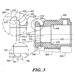
- the leading tab (600) has a leading tab perimeter edge (610), a leading tab primary contact surface (620), a leading tab centering ledge (640), and a leading tab centering flank (650), as seen in FIG. 3 .
- the leading tab (700) extends radially a leading tab height (630) from leading edge (510).
- the leading tab centering flank (650) extends from the root surface (530) to the leading tab centering ledge (640).
- a flank angle (652) exists between the leading tab centering flank (650) and the leading tab centering ledge (640).
- the leading tab centering ledge (640) has a ledge width (642) which is the maximum width of the leading tab centering ledge (640) as measured from the intersection of the leading tab centering ledge (640) with the leading tab centering flank (650) and the intersection of the leading tab centering ledge (640) and the leading tab primary contact surface (620).
- the flank angle (652) is between approximately ninety-one degrees and approximately one hundred and seventy-nine degrees.
- the distance from leading tab primary contact surface (620) to the body distal end (410) is greater than 150% of the box thickness (225), and the ledge width (642) is substantially equal to or less than the box thickness (225).
- the root surface (530) defines a root surface diameter (532) having a root surface central axis (533) that is offset from the central axis (436), as seen in FIG. 3 .
- the root surface (530) a minimum root surface width (534) which is defined as a distance from the box engagement region secondary edge (520) to the nearest intersection of the root surface (530) and the leading tab centering flank (650). The functioning of the root surface (530) during assembly will be described in greater detail below.
- the follower tab (700) also has a perimeter edge (710) and a primary contact surface (720).
- the leading tab (700) extends radially a leading tab height (730) from the box engagement region leading edge (510).
- the leading tab perimeter edge (610) and the follower tab perimeter edge (710) form a tab perimeter diameter (760), as shown in FIG. 2 .
- the tab perimeter diameter (760) is larger than the knockout diameter (232) to permit the body (400) to be secured to the junction box (200).
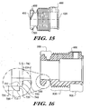
- the follower tab (700) has a follower tab centering ledge (740) and a follower tab centering flank (750) which extends from the root surface (530) to the follower tab centering ledge (740), as seen in FIGS. 15 and 16 .
- a follower tab flank angle (752) exists between the follower tab centering flank (750) and the follower tab centering ledge (740).
- the follower tab centering ledge (740) has a follower tab ledge width (742) which is the maximum width of the follower tab centering ledge (740) as measured from the intersection of the follower tab centering ledge (740) with the follower tab centering flank (750) and the intersection of the follower tab centering ledge (740) and the follower tab primary contact surface (720).
- the follower tab flank angle (752) is between approximately ninety-one degrees and approximately one hundred and seventy-nine degrees.
- the leading and follower tab primary contact surfaces (620,720) have grip enhancing features (622,722).
- the grip enhancing features (622,722) reduce the relative motion between the leading and follower tab primary contact surfaces (620,720) and the box interior surface (210).
- the grip enhancing features (620,720) may be adhesive, a pressure sensitive adhesive that is activated by removal of a releasable covering, or a rubber-like gasket or o-ring.
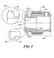
- the grip enhancing features (622,722) are gripping projections (623,723), as seen in the exploded views in FIG. 4 , and comprise one or more of the group consisting of knurling, checkering, knobs, teeth, texturing of the surface, or a plurality of surface features that come into contact with the box interior surface (210) and increase the frictional forces between the leading and follower tabs (600,700) and the box interior surface (210) substantially preventing rotation of the body (400).
- the body (400) has two radially extending tabs, that is, the leading tab (600) and the follower tab (700).
- leading tab (600) may operate with the root surface (530), or multiple leading tabs (600) in combination with a plurality of follower tabs (700) in operation with the root surface (530) where the tabs (600,700) are positioned in a generally opposing manner
- follower tabs (700) in operation with the root surface (530) where the tabs (600,700) are positioned in a generally opposing manner will also provide the inventive assembly system of the present invention, as will be more fully explained below.
- FIG. 5 shows the nut engagement region (800) which has a nut engagement region proximal end (810), a nut engagement region distal end (820), and a plurality of nut engagement region threads (830).
- the nut engagement region (800) cooperates with the compression nut (1000), as explained in greater detail below.
- the nut engagement region (800) is formed with a nut stop (840).
- the nut stop (840) is positioned at the nut engagement region proximal end (810) adjacent to the conduit engagement region (900).
- the nut stop (840) facilitates the assembly of the system (100) at the factory and removal of the system (100) from the junction box (200) by preventing the compression nut (1000) from being rotated off the body proximal end (420).
- the conduit engagement region (900) has a conduit compression system (920) for frictionally securing the conduit (300) within the body (400), as seen in FIG. 6 .
- the conduit compression system (920) is a setscrew (922) and a setscrew receiver (924).
- the setscrew receiver (924) is formed in the conduit engagement region (900) and extends from the body interior surface (430) to the body exterior surface (450). The setscrew (922) is threaded through the setscrew receiver (924).
- a conduit inlet chamfer (910) may be formed in the conduit engagement region (900) to ease initial insertion of the conduit (300) into the body proximal end (420).
- the body exterior surface (450) at the conduit engagement region (900) defines a body exterior surface inlet diameter (452), as seen in FIG. 2 , and the root surface diameter (532) is less than the body exterior surface inlet diameter (452).
- FIGS. 12 - 14 illustrate an embodiment of the present invention where the conduit engagement region (900) is a removable conduit engagement region (930).
- the removable conduit engagement region (930) has a threaded connector (932) for cooperating with the body interior surface (430) having a plurality of internal body threads (448).
- Figure 14 illustrates the removable conduit engagement region (930) threaded into the body (400).
- the removable engagement region (930) may be a commercially available electrical connector without the locknut. Therefore, all of the numerous advantages of the invention, as stated below, are realized by forming the body (400) with the internal body threads (448) which are sized to cooperate with the male threaded end of a prior art electrical connector.
- the electrical conduit to junction box connection system (100) has two primary components - the body (400), as described above, and the compression nut (1000).
- the compression nut (1000) which is shown separate from the body (400), has an exterior surface (1020) and a nut interior surface (1010) having a plurality of nut threads (1012) that cooperate with the nut engagement region threads (830).
- the nut exterior surface (1020) may be formed with texturing to facilitate operation manually or formed with features for cooperating with tools.
- the compression nut (1000) has a nut free edge (1040) that may butt against the nut stop (840).
- the nut stop (840) as shown in FIG.
- the compression nut (1000) also has a nut contact edge (1030) having a nut contact surface (1032) for engaging the box exterior surface (220).
- the compression nut contact surface (1032) has a grip enhancing feature (1034) to reduce the relative motion between the compression nut (1000) and the box exterior surface (220) while in contact with one another.
- the grip enhancing feature may be adhesive, a pressure sensitive adhesive that is activated by removal of a releasable covering, or a rubber-like gasket or o-ring.
- the grip enhancing feature (1034) is a gripping projection (1035), as shown in FIG. 4 .
- the gripping projection (1035) comprises one or more of the group consisting of knurling, knobs, checkering, teeth, texturing of the surface, or a plurality of surface features that come into contact with the box exterior surface (220).
- the gripping projection (1035) increases the frictional forces between compression nut (1000) and the box exterior surface (220) substantially preventing unintentional rotation of the compression nut (1000).
- FIGS. 7 - 11 The orientation of the various elements of the system (100) imparts the desired functionality of the system (100).
- the installation of the system (100) is illustrated in FIGS. 7 - 11 .
- FIG. 7 illustrates that once the knockout (230) is exposed or created, the leading tab (600) is inserted from the outside of the junction box (200) into the knockout (230) by angling the body (400) such that the central axis (436) is not orthogonal to the knockout (230). Once the leading tab (600) is on the inside of the junction box (200), the knockout edge (234) is brought into contact with the root surface (530), as shown in FIG. 8 .
- the central axis (436) is then reoriented orthogonally to the knockout (230) while holding the knockout edge (234) in contact with the root surface (530), as shown in FIG. 9 .
- the root surface central axis (533) is offset from the central axis (436) toward the follower tab (700) by at least 8% to accommodate a larger variation in standard knockout diameters thereby providing for easier installation.
- the follower tab (700) passes through the knockout (230) into the junction box (200). At this point, both the leading and follower tabs (600,700) are on the inside of the junction box (200).
- the body (400) is drawn tight to the junction box (200), as seen in FIG. 10 , by rotating the compression nut (1000) so the nut contact edge (1030) presses against the box exterior surface (220). By continuing to rotate the compression nut (1000), the nut contact edge (1030) forces the knockout edge (234) onto the leading tab centering flank (650). Further rotation of the compression nut (1000) pushes the knockout edge (234) onto the leading tab centering ledge (640), substantially centering the body (400) in the knockout (230), as seen in FIG. 11 .
- the leading tab and follower tab primary contact surfaces (620,720) engage the box interior surface (210). Additional rotation of the compression nut (1000) compresses the junction box (200) between the compression nut contact surface (1032) and the leading and follower tab primary contact surfaces (620,720). Actual tightening can be accomplished by manual manipulation or by application of tools to the nut exterior surface (1020). In an embodiment of the present invention, as seen in FIG.
- the compression nut (1000) is rotated in the counter-clockwise direction to tighten the compression nut (1000) against the junction box exterior surface (220), that is, the nut threads (1012) advance to the left, commonly referred to as left-handed threads.
- the left-handed threaded design of the nut engagement region threads (830) and the compression nut threads (1012) is useful for maintaining a tight connection to junction boxes installed on equipment which have clockwise rotational motion.
- the advantages of the system (100) are readily apparent to those skilled in the art.
- the body (400) can be easily removed from the junction box (200) and then later reused. Most importantly, however, the compression nut (1000) remains attached to the body (400). In other words, there is no need to remove the compression nut (1000) to disconnect the body (400) from the junction box (200).
- the body (400) and the compression nut (1000) remain an integral unit through any number of connections and disconnections.
- the system (100) may also be easily installed while wearing gloves because the prior art locknut is absent.
- the prior art locknut requires a great degree of tactility to hold and to thread onto the male threaded connector, the difficulty of which is accentuated and prolonged when wearing gloves. So, even in frigid temperatures, to reduce the installation time, electricians generally do not wear gloves to protect their hands. Additionally, the system (100) does not require access to the interior of the junction box (200) to rigidly connect the conduit (300). All connections between the conduit and the junction box (200) can proceed without opening or removing the cover of the junction box (200).
- the conduit (300) is attached to the body (400).
- the conduit (300) is attached to the body (400) by inserting the conduit leading edge (330) to the conduit stop (438).
- the conduit compression system (920) frictionally secures the conduit (300) to the body (400).
- a plurality of electrical wires or cables is passed through the conduit (300), through the body interior surface (430), and into the junction box (200).
- the conduit (300) may be inserted through the body (400) into the junction box (200), or at least inserted through the body (400) to an adequate depth to assure a firm grip by the conduit engagement region (900) on the conduit (300) or cable.
- This embodiment may be suitable for passing flexible cable, portable cord and the like into the junction box (200).
- the electrical conduit to junction box connection system answers a long felt need for an electrical connector which can be installed quickly and easily without tools, does not require access to the interior of a junction box, and does not need to be disassembled before connecting it to an electrical enclosure.
- the electrical connector has utility, among other uses, in connection of conduit to junction boxes.
- the present invention discloses an electrical connector having a body and a compression nut.
- the body has a box engagement region, a nut engagement region, and a conduit engagement region.
- the box engagement region facilitates connection with the junction box.
- the nut engagement region cooperates with the compression nut to rigidly fix the body to the junction box.
- the conduit engagement region cooperates with a variety of conduit, cables, and other electrical conductors.
Landscapes
- Engineering & Computer Science (AREA)
- Architecture (AREA)
- Civil Engineering (AREA)
- Structural Engineering (AREA)
- Connection Or Junction Boxes (AREA)
- Connection Of Plates (AREA)
- Connections Arranged To Contact A Plurality Of Conductors (AREA)
- Infusion, Injection, And Reservoir Apparatuses (AREA)
- Laying Of Electric Cables Or Lines Outside (AREA)
- Details Of Connecting Devices For Male And Female Coupling (AREA)
Claims (15)
- Système de connexion (100) d'un conduit électrique à un boîtier de raccordement pour connecter de façon détachable un boîtier de raccordement (200) et un conduit (300), dans lequel le boîtier de raccordement (200) a une surface intérieure (210) de boîtier, une surface extérieure (220) de boîtier, une épaisseur (225) de boîtier, et est formé avec un défoncement (230) s'étendant de la surface intérieure (210) de boîtier jusqu'à la surface extérieure (220) de boîtier ayant un diamètre (232) de défoncement et un bord (234) de défoncement, et le conduit (300) a une surface intérieure (310) de conduit, une surface extérieure (320) de conduit, une épaisseur (340) de conduit, et un bord avant (330) de conduit, comprenant : un corps (400) ayant une extrémité distale (410), une extrémité proximale (420), une surface extérieure (450) de corps, et une surface intérieure (430) de corps, dans lequel la surface intérieure (430) de corps définit un diamètre d'entrée (432), un diamètre de sortie (434) qui est coaxial avec le diamètre d'entrée (432), et dans lequel le corps (400) inclut une région d'engagement de boîtier (500) qui coopère avec le boîtier de raccordement (200), une région d'engagement d'écrou (800), et une région d'engagement de conduit (900) qui coopère avec le conduit (300), caractérisé en ce que :(a) la région d'engagement de boîtier (500) a un bord avant (510) et un bord secondaire (520), avec une surface de base (530), une languette avant (600), et une languette suiveuse (700) située entre le bord avant (510) et le bord secondaire (520), dans laquelle :(i) la surface de base (530) définit un diamètre (532) de surface de base qui n'est pas coaxial avec le diamètre d'entrée (432) de corps ou le diamètre de sortie (434) de corps ;(ii) la languette avant (600) a un bord de périmètre (610) de languette avant, une surface de contact primaire (620) de languette avant, un rebord de centrage (640) de languette avant, et un flanc de centrage (650) de languette avant s'étendant de la surface de base (530) jusqu'au rebord de centrage (640) de languette avant selon un angle de flanc (652), mesuré du rebord de centrage (640) de languette avant jusqu'au flanc de centrage (650) de languette avant, qui est entre approximativement quatre-vingt-onze degrés et approximativement cent soixante-dix-neuf degrés ;(iii) la languette suiveuse (700) a un bord de périmètre (710) de languette suiveuse, et une surface de contact primaire (720) de languette suiveuse, dans laquelle le bord de périmètre (610) de languette avant et le bord de périmètre (710) de languette suiveuse définissent un diamètre de périmètre (760) de languettes qui est plus grand que le diamètre (232) de défoncement ;(b) la région d'engagement d'écrou (800) a une extrémité proximale (810) de région d'engagement d'écrou, une extrémité distale (820) de région d'engagement d'écrou, et une pluralité de filets (830) de région d'engagement d'écrou ; et(c) la région d'engagement de conduit (900) a un système de compression (920) de conduit qui fixe par frottement une partie du conduit (300) à l'intérieur du corps (400) ; et un écrou de compression (1000) ayant une surface intérieure (1010) d'écrou ayant une pluralité de filets (1012) d'écrou qui coopèrent avec les filets (830) de région d'engagement d'écrou, une surface extérieure (1020) d'écrou, un bord de contact (1030) d'écrou ayant une surface de contact (1032) d'écrou, et un bord libre (1040) d'écrou, dans laquelle après insertion de la languette avant (600) et de la languette suiveuse (700) à travers le défoncement (230) en disposant le corps (400) selon un angle de telle manière qu'un axe central (436) n'est pas orthogonal au défoncement (230) et ensuite en faisant passer la languette avant (600) à travers le défoncement (230) et en amenant le bord (234) de défoncement en contact avec la surface de base (530) de façon à ce que la languette suiveuse (700) puisse passer à travers le défoncement (230), le corps (400) est amené en relation étroite avec le boîtier de raccordement (200) en faisant tourner l'écrou de compression (1000) de telle façon que la coopération des filets (1012) d'écrou et des filets (830) de région d'engagement d'écrou force l'écrou de compression (1000) vers la languette avant (600) et la languette suiveuse (700) de telle sorte que le flanc de centrage (650) de languette avant dirige le bord (234) de défoncement sur le rebord de centrage (640) de languette avant, centrant ainsi essentiellement l'axe central (436) dans le défoncement (230) et pinçant le boîtier de raccordement (200) entre l'écrou de compression (1000) et la languette avant (600) et la languette suiveuse (700), fixant ainsi de façon détachable le corps (400) au boîtier de raccordement (200)
- Système de connexion (100) d'un conduit électrique à un boîtier de raccordement selon la revendication 1, incluant en outre une butée (438) de conduit qui se projette à partir de la surface intérieure (430) de corps d'une distance de projection (440) de butée de conduit, limitant ainsi la distance sur laquelle le bord avant (330) de conduit peut s'étendre dans le corps (400)
- Système de connexion (100) d'un conduit électrique à un boîtier de raccordement selon la revendication 1, dans lequel la distance de la surface de contact primaire (620) de languette avant jusqu'à l'extrémité distale (410) de corps est supérieure à 150% de l'épaisseur (225) de boîtier et le rebord de centrage (640) de languette avant a une largeur (642) de rebord qui est essentiellement égale ou inférieure à l'épaisseur (225) de boîtier
- Système de connexion (100) d'un conduit électrique à un boîtier de raccordement selon la revendication 1, dans lequel la surface de base (530) a une largeur minimum (534) de surface de base qui est la distance la plus petite entre le bord secondaire (520) de région d'engagement de boîtier et une intersection entre le flanc de centrage (650) de languette avant et la surface de base (530) et où la largeur minimum (534) de surface de base est au moins 150% de l'épaisseur (225) de boîtier
- Système de connexion (100) d'un conduit électrique à un boîtier de raccordement selon la revendication 1, dans lequel la languette suiveuse (700) a un rebord de centrage (740) de languette suiveuse et un flanc de centrage (750) de languette suiveuse s'étendant de la surface de base (530) jusqu'au rebord de centrage (740) de languette suiveuse selon un angle (752) de flanc, mesuré du rebord de centrage (740) de languette suiveuse jusqu'au flanc de centrage (750) de languette suiveuse qui est entre approximativement quatre-vingt-onze degrés et approximativement cent soixante-dix-neuf degrés, et dans lequel le corps (400) est amené en relation étroite avec le boîtier de raccordement (200) en faisant tourner l'écrou de compression (1000) de telle façon que la coopération des filets (1012) d'écrou et des filets (830) de région d'engagement d'écrou force l'écrou de compression (1000) vers la languette avant (600) et la languette suiveuse (700) de telle sorte que le flanc de centrage (750) de languette suiveuse dirige le bord (234) de défoncement sur le rebord de centrage (740) de languette suiveuse, centrant ainsi essentiellement l'axe central (436) dans le défoncement (230) et pinçant le boîtier de raccordement (200) entre l'écrou de compression (1000) et la languette avant (600) et la languette suiveuse (700), fixant ainsi de façon détachable le corps (400) au boîtier de raccordement (200)
- Système de connexion (100) d'un conduit électrique à un boîtier de raccordement selon la revendication 1, dans lequel la surface de contact primaire (620) de languette avant a une caractéristique (622) d'amélioration de prise de languette avant et la surface de contact primaire (720) de languette suiveuse a une caractéristique (722) d'amélioration de prise de languette suiveuse, de sorte que lorsque la surface de contact primaire (620) de languette avant et la surface de contact primaire (720) de languette suiveuse viennent en contact avec la surface intérieure (210) de boîtier, la caractéristique (622) d'amélioration de prise de languette avant et la caractéristique (722) d'amélioration de prise de languette suiveuse empêchent essentiellement la rotation du corps (400)
- Système de connexion (100) d'un conduit électrique à un boîtier de raccordement selon la revendication 6, dans lequel la caractéristique (622) d'amélioration de prise de languette avant est une projection (623) de prise de languette avant et la caractéristique (722) d'amélioration de prise de languette suiveuse est une projection (723) de prise de languette suiveuse
- Système de connexion (100) d'un conduit électrique à un boîtier de raccordement selon la revendication 1, dans lequel (a) la surface de contact primaire (620) de languette avant a une caractéristique (622) d'amélioration de prise de languette avant et la caractéristique (622) d'amélioration de prise de languette avant est une projection (623) de prise de languette avant, et la caractéristique (722) d'amélioration de prise de languette suiveuse est une projection (723) de prise de languette suiveuse, et lorsque la caractéristique (622) d'amélioration de prise de languette avant et la caractéristique (722) d'amélioration de prise de languette suiveuse viennent en contact avec la surface intérieure (210) de boîtier, les forces de frottement entre la surface intérieure (210) de boîtier et la languette avant (600) et la languette suiveuse (700) sont de façon générale améliorées ;(b) l'écrou de compression (1000) a une projection (1035) de prise qui vient au contact de la surface extérieure (220) de boîtier, ce qui augmente les forces de frottement entre la surface extérieure (220) de boîtier et l'écrou de compression (1000) ; et(c) la projection (623) de prise de languette avant, la projection (723) de prise de languette suiveuse et la projection (1035) de prise d'écrou de compression empêchent essentiellement que l'écrou de compression (1000) et le corps (400) tournent l'un par rapport à l'autre, maintenant ainsi le corps (400) fixé de façon rigide au boîtier de raccordement (200)
- Système de connexion (100) d'un conduit électrique à un boîtier de raccordement selon la revendication 1, dans lequel le système de compression (920) de conduit est une vis de réglage (922) coopérant avec un récepteur (924) de vis de réglage, formé dans la région d'engagement de conduit (900), s'étendant de la surface intérieure (430) de corps jusqu'à la surface extérieure (450) de corps où le bord avant (330) de conduit est inséré dans l'extrémité proximale (420) de corps au-delà du récepteur (924) de vis de réglage, de telle sorte que, lorsque la vis de réglage (922) est fait tourner dans le récepteur (924) de vis de réglage, la vis de réglage (922) vient au contact de la surface extérieure (320) de conduit, maintenant de façon rigide le conduit (300) sur le corps (400)
- Système de connexion (100) d'un conduit électrique à un boîtier de raccordement selon la revendication 2, dans lequel la butée (438) de conduit est située à une distance d'insertion (439) de conduit à partir de l'extrémité proximale (420) et la distance d'insertion (439) de conduit est au moins 50% de la distance de l'extrémité distale (410) à l'extrémité proximale (420).
- Système de connexion (100) d'un conduit électrique à un boîtier de raccordement selon la revendication 2, dans lequel le diamètre de sortie (434) est plus petit que le diamètre d'entrée (432) d'au moins 50% de l'épaisseur (340) de conduit, et dans lequel la surface extérieure (450) de corps au niveau de la région d'engagement de conduit (900) définit un diamètre d'entrée (452) de surface extérieure de corps et le diamètre (532) de surface de base est inférieur au diamètre d'entrée (452) de surface extérieure de corps
- Système de connexion (100) d'un conduit électrique à un boîtier de raccordement selon la revendication 1, dans lequel les filets (830) de région d'engagement d'écrou et les filets (1012) d'écrou de compression sont des filets à gauche
- Système de connexion (100) d'un conduit électrique à un boîtier de raccordement selon la revendication 2, dans lequel le diamètre de sortie (434) est plus petit que le diamètre d'entrée (432) d'au moins 50% de l'épaisseur (340) de conduit, et dans lequel la région d'engagement d'écrou (800) inclut une butée (840) d'écrou au niveau de l'extrémité proximale (810) de région d'engagement d'écrou pour empêcher la course de l'écrou de compression (1000) vers la région d'engagement de conduit (900) au-delà d'un point prédéterminé
- Système de connexion (100) d'un conduit électrique à un boîtier de raccordement selon la totalité des revendications 3, 4, 9, 12, et 13, dans lequel la distance de projection (440) de butée de conduit est entre approximativement 25% et approximativement 100% de l'épaisseur (340) de conduit, limitant ainsi la distance sur laquelle le bord avant (330) de conduit peut s'étendre à l'intérieur du corps (400), et dans lequel le diamètre (532) de surface de base a un axe central (533) de surface de base qui est décalé par rapport à l'axe central (436) d'au moins 8% du diamètre de périmètre (760) de languettes.
- Système de connexion (100) d'un conduit électrique à un boîtier de raccordement selon la totalité des revendications 3, 4, 9, et 13, dans lequel la distance de projection (440) de butée de conduit est entre approximativement 25% et approximativement 100% de l'épaisseur (340) de conduit, limitant ainsi la distance sur laquelle le bord avant (330) de conduit peut s'étendre à l'intérieur du corps (400), et dans lequel la languette suiveuse (700) a un rebord de centrage (740) de languette suiveuse et un flanc de centrage (750) de languette suiveuse s'étendant de la surface de base (530) jusqu'au rebord de centrage (740) de languette suiveuse selon un angle (752) de flanc, mesuré du rebord de centrage (740) de languette suiveuse jusqu'au flanc de centrage (750) de languette suiveuse qui est entre approximativement quatre-vingt-onze degrés et approximativement cent soixante-dix-neuf degrés
Applications Claiming Priority (2)
| Application Number | Priority Date | Filing Date | Title |
|---|---|---|---|
| US11/291,627 US7078623B1 (en) | 2005-11-30 | 2005-11-30 | Electrical conduit to junction box connection system |
| PCT/US2006/045649 WO2007064683A2 (fr) | 2005-11-30 | 2006-11-28 | Systeme de connexion de conduit electrique a une boite de raccordement |
Publications (3)
| Publication Number | Publication Date |
|---|---|
| EP1969689A2 EP1969689A2 (fr) | 2008-09-17 |
| EP1969689A4 EP1969689A4 (fr) | 2009-12-02 |
| EP1969689B1 true EP1969689B1 (fr) | 2011-01-05 |
Family
ID=36659100
Family Applications (1)
| Application Number | Title | Priority Date | Filing Date |
|---|---|---|---|
| EP06838550A Not-in-force EP1969689B1 (fr) | 2005-11-30 | 2006-11-28 | Sytème de connexion de conduit électrique à une boîte de raccordement |
Country Status (7)
| Country | Link |
|---|---|
| US (1) | US7078623B1 (fr) |
| EP (1) | EP1969689B1 (fr) |
| AT (1) | ATE494650T1 (fr) |
| CA (1) | CA2631588A1 (fr) |
| DE (2) | DE602006019493D1 (fr) |
| TW (1) | TWI305970B (fr) |
| WO (1) | WO2007064683A2 (fr) |
Families Citing this family (45)
| Publication number | Priority date | Publication date | Assignee | Title |
|---|---|---|---|---|
| JP3996931B2 (ja) * | 2004-03-22 | 2007-10-24 | 株式会社 イシハラ | 鉄骨梁の開口補強工法 |
| US7220923B1 (en) * | 2006-06-30 | 2007-05-22 | Internatioinal Metal Hose Company | Clip-on electrical conduit connector |
| US8141915B2 (en) * | 2006-08-02 | 2012-03-27 | Norgren, Inc. | Modular rotary connection system with a separate locking piece |
| US7631902B2 (en) * | 2007-02-05 | 2009-12-15 | S-P Products, Inc. | Transition coupling |
| DE202008001842U1 (de) | 2008-02-09 | 2008-04-10 | Jacob Gmbh Elektrotechnische Fabrik | Steckvorrichtung |
| US8129634B2 (en) * | 2008-02-29 | 2012-03-06 | Sigma Electric Manufacturing Corporation | Conduit connector |
| US7868252B2 (en) * | 2008-06-07 | 2011-01-11 | Rifet Spahic | Electrical locking hub nut |
| EP2149937B1 (fr) * | 2008-08-01 | 2013-01-09 | PPC, A Division of John Mezzalingua Associates, Inc. | Connecteur coaxial et procédé pour connecter le connecteur coaxial à un composant d'accouplement |
| US8901441B2 (en) * | 2008-10-08 | 2014-12-02 | Sigma Electric Manufacturing Corporation | Conduit connector and methods for making and using the same |
| GB0919682D0 (en) * | 2009-11-11 | 2009-12-23 | Hi Lex Cable System Company Ltd | Damper |
| US8857039B2 (en) | 2010-02-19 | 2014-10-14 | Sigma Electric Manufacturing Corporation | Electrical box conduit connectors and methods for making and using the same |
| US8803008B2 (en) | 2011-03-03 | 2014-08-12 | Sigma Electric Manufacturing Corporation | Conduit connector and methods for making and using the same |
| US8944267B2 (en) | 2011-03-29 | 2015-02-03 | Ppc Broadband, Inc. | Configurable enclosure |
| US10833496B2 (en) | 2011-03-29 | 2020-11-10 | Ppc Broadband, Inc. | Configurable enclosure |
| CA2788787C (fr) | 2011-09-01 | 2019-06-04 | Sigma Electric Manufacturing Corporation | Connecteur de conduite et ses methodes de fabrication et d'utilisation |
| US9431808B1 (en) | 2012-07-26 | 2016-08-30 | Vernon Perkins | Electrical connector |
| US9136653B2 (en) * | 2013-10-18 | 2015-09-15 | JTech Solutions, Inc. | Enclosed power outlet |
| US9331430B2 (en) | 2013-10-18 | 2016-05-03 | JTech Solutions, Inc. | Enclosed power outlet |
| US10145496B2 (en) | 2014-06-13 | 2018-12-04 | Schlumberger Technology Corporation | Rotary shouldered connections and thread design |
| US10662722B2 (en) | 2014-06-13 | 2020-05-26 | Schlumberger Technology Corporation | Threaded connections and downhole tools incorporating the same |
| US10160033B2 (en) | 2014-06-23 | 2018-12-25 | Schlumberger Technology Corporation | Cold rolling devices and cold rolled rotary shouldered connection threads |
| US9472933B2 (en) | 2014-10-14 | 2016-10-18 | Saeed Nikayin | Conduit locking connector |
| US9608417B2 (en) | 2015-04-07 | 2017-03-28 | Bridgeport Fittings, Inc. | Electrical fitting for non-metallic electrical cable |
| USD775590S1 (en) | 2015-04-07 | 2017-01-03 | Bridgeport Fittings, Inc. | Electrical fitting for non-metallic electrical cable |
| US20170110224A1 (en) * | 2015-10-16 | 2017-04-20 | New Green Co., Ltd. | Cable fixator |
| US9496697B1 (en) | 2015-10-16 | 2016-11-15 | Imagineering Plus Plus Llc | Roof top junction box |
| US9705295B1 (en) | 2016-01-13 | 2017-07-11 | Bridgeport Fittings, Inc. | Slip conduit connector and system and method of installing electrical conduit with a slip conduit connector |
| US10669787B2 (en) * | 2016-12-09 | 2020-06-02 | Schlumberger Technology Corporation | Pump rod connection |
| US10767801B2 (en) | 2017-03-03 | 2020-09-08 | Ripley's, Inc. | Conduit coupling adapter |
| US10205283B2 (en) | 2017-04-13 | 2019-02-12 | JTech Solutions, Inc. | Reduced cross-section enclosed power outlet |
| US10461443B2 (en) | 2017-05-02 | 2019-10-29 | Bridgeport Fittings, Llc | Split grounding bushing with removable spacer |
| US10135230B1 (en) * | 2017-05-02 | 2018-11-20 | Bridgeport Fittings, Inc. | Electrical connector with removable spacer |
| US10027039B1 (en) | 2017-05-02 | 2018-07-17 | Bridgeport Fittings, Inc. | Threadless grounding bushing with removable spacer |
| USD875689S1 (en) | 2018-02-09 | 2020-02-18 | Bridgeport Fittings, Llc | Cable securing device for non-metallic electrical cable |
| USD843321S1 (en) | 2018-03-26 | 2019-03-19 | JTech Solutions, Inc. | Extendable outlet |
| USD841592S1 (en) | 2018-03-26 | 2019-02-26 | JTech Solutions, Inc. | Extendable outlet |
| US11876360B2 (en) * | 2019-03-08 | 2024-01-16 | S-P Products Inc. | Conduit coupling assembly |
| CA3154537A1 (fr) * | 2019-11-20 | 2021-05-27 | Hubert Rieger | Systeme de raccordement pour poutres de monorail |
| US10958051B1 (en) * | 2020-01-28 | 2021-03-23 | Anthony James Howard | Electrical conduit connector |
| US11588271B2 (en) * | 2020-06-22 | 2023-02-21 | AFC Cable Systems, Inc. | Modular connector for rigid tubing |
| USD999742S1 (en) | 2021-04-01 | 2023-09-26 | JTech Solutions, Inc. | Safety interlock outlet box |
| US11670924B2 (en) | 2021-10-22 | 2023-06-06 | Abb Schweiz Ag | Fitting connections for corrosion resistant electrical conduits |
| US11581717B1 (en) | 2021-11-02 | 2023-02-14 | Esdec, Inc. | Mountable electrical enclosure with conduit passthrough |
| US12368293B2 (en) | 2022-01-11 | 2025-07-22 | JTech Solutions, Inc. | Safety interlocks for outlets |
| US12529269B2 (en) | 2023-03-15 | 2026-01-20 | Schlumberger Technology Corporation | Thread form for drill bit application |
Family Cites Families (20)
| Publication number | Priority date | Publication date | Assignee | Title |
|---|---|---|---|---|
| US377506A (en) | 1888-02-07 | Coupling for boilers | ||
| US1131399A (en) | 1911-06-23 | 1915-03-09 | Handy Mfg Company | Outlet-box. |
| US1049283A (en) | 1912-11-15 | 1912-12-31 | Carl Westphal | Pipe-joint. |
| US1355450A (en) | 1917-02-17 | 1920-10-12 | Elmer Conrad Carlson | Coupling |
| US2241293A (en) | 1940-06-24 | 1941-05-06 | Ransom D Campbell | Connector |
| US2457235A (en) | 1946-10-21 | 1948-12-28 | Hoehn Karl | Connector for electric receptacles |
| US2466504A (en) | 1947-04-05 | 1949-04-05 | Elwood D Stoyer | Holding device for electric cables |
| US2973212A (en) | 1960-03-28 | 1961-02-28 | Leslie W Rose | Electric connectors for outlet boxes |
| US3788582A (en) | 1973-03-22 | 1974-01-29 | All Steel Inc | Connector for non-metallic sheathed cable |
| US3981061A (en) | 1974-09-26 | 1976-09-21 | Gulf & Western Manufacturing Company | Method for joining pipes |
| US4151363A (en) | 1976-12-20 | 1979-04-24 | Nichols Wayne L | Method and apparatus for joining electrical conductors to junction boxes |
| US4699217A (en) | 1984-06-12 | 1987-10-13 | Victaulic Company Of America | Direct connect plumbing fixture |
| US4711974A (en) | 1984-10-26 | 1987-12-08 | The Carlon Company | Adapter fitting for connecting flexible conduit to electrical outlet boxes |
| US4641863A (en) | 1985-11-12 | 1987-02-10 | Sami Shemtov | Connector for coupling a conduit to a junction box |
| US5200575A (en) | 1991-01-25 | 1993-04-06 | Sheehan Robert K | Connector assembly for conduit |
| US5866853A (en) * | 1993-10-07 | 1999-02-02 | Sheehan; Robert K. | Liquid-tight, strain-relief connector for connecting conduit and the like |
| FR2766913B1 (fr) | 1997-07-30 | 1999-09-24 | Valeo Thermique Moteur Sa | Tubulure d'une boite collectrice, notamment d'un echangeur de chaleur d'une installation de ventilation chauffage et/ou climatisation de vehicule automobile, et procede de fixation de cette tubulure |
| CA2269918A1 (fr) | 1998-04-27 | 1999-10-27 | Robert K. Sheehan | Raccord de conduit d'une serrure de surete |
| DE10033911C1 (de) | 2000-07-12 | 2002-04-04 | Hummel Anton Verwaltung | Anschlussarmatur für längliche Körper mit Spannzange |
| US6642451B1 (en) * | 2001-10-22 | 2003-11-04 | Arlington Industries, Inc. | Electrical connector |
-
2005
- 2005-11-30 US US11/291,627 patent/US7078623B1/en not_active Expired - Fee Related
-
2006
- 2006-11-13 TW TW095141992A patent/TWI305970B/zh active
- 2006-11-28 AT AT06838550T patent/ATE494650T1/de not_active IP Right Cessation
- 2006-11-28 DE DE602006019493T patent/DE602006019493D1/de active Active
- 2006-11-28 CA CA002631588A patent/CA2631588A1/fr not_active Abandoned
- 2006-11-28 WO PCT/US2006/045649 patent/WO2007064683A2/fr not_active Ceased
- 2006-11-28 DE DE06838550T patent/DE06838550T1/de active Pending
- 2006-11-28 EP EP06838550A patent/EP1969689B1/fr not_active Not-in-force
Also Published As
| Publication number | Publication date |
|---|---|
| WO2007064683A3 (fr) | 2007-10-18 |
| CA2631588A1 (fr) | 2007-06-07 |
| TW200729649A (en) | 2007-08-01 |
| WO2007064683A2 (fr) | 2007-06-07 |
| TWI305970B (en) | 2009-02-01 |
| ATE494650T1 (de) | 2011-01-15 |
| US7078623B1 (en) | 2006-07-18 |
| EP1969689A4 (fr) | 2009-12-02 |
| DE06838550T1 (de) | 2010-01-28 |
| DE602006019493D1 (de) | 2011-02-17 |
| EP1969689A2 (fr) | 2008-09-17 |
Similar Documents
| Publication | Publication Date | Title |
|---|---|---|
| EP1969689B1 (fr) | Sytème de connexion de conduit électrique à une boîte de raccordement | |
| US8129634B2 (en) | Conduit connector | |
| USRE47893E1 (en) | Conduit connector and methods for making and using the same | |
| CA2788787C (fr) | Connecteur de conduite et ses methodes de fabrication et d'utilisation | |
| US8901441B2 (en) | Conduit connector and methods for making and using the same | |
| US5422437A (en) | Electrical connector assembly | |
| US8857039B2 (en) | Electrical box conduit connectors and methods for making and using the same | |
| US6527302B1 (en) | Universal conduit body and system | |
| US6616194B1 (en) | Liquid tight connector | |
| JPH077837A (ja) | ケーブルグランド | |
| US9800030B2 (en) | Conduit receivers | |
| CA2890494C (fr) | Raccords et methodes de fabrication et d'utilisation desdits raccords | |
| US11451027B2 (en) | Press coupler for electrical conduit | |
| EP1790053B1 (fr) | Écrou de mise à la terre électrique | |
| US9431808B1 (en) | Electrical connector | |
| EA037200B1 (ru) | Срезной винт | |
| CA3106632C (fr) | Connecteur de conduite electrique | |
| US7220923B1 (en) | Clip-on electrical conduit connector | |
| CA2853404C (fr) | Raccords de conduite et procedes pour fabriquer et utiliser ceux-ci | |
| CA2770855C (fr) | Raccord de conduit et procede de fabrication et d'utilisation | |
| CA2821441C (fr) | Connecteur electrique |
Legal Events
| Date | Code | Title | Description |
|---|---|---|---|
| PUAI | Public reference made under article 153(3) epc to a published international application that has entered the european phase |
Free format text: ORIGINAL CODE: 0009012 |
|
| 17P | Request for examination filed |
Effective date: 20080630 |
|
| AK | Designated contracting states |
Kind code of ref document: A2 Designated state(s): AT BE BG CH CY CZ DE DK EE ES FI FR GB GR HU IE IS IT LI LT LU LV MC NL PL PT RO SE SI SK TR |
|
| A4 | Supplementary search report drawn up and despatched |
Effective date: 20091029 |
|
| RIC1 | Information provided on ipc code assigned before grant |
Ipc: F16L 5/06 20060101ALI20091023BHEP Ipc: H02G 3/06 20060101AFI20080728BHEP |
|
| 17Q | First examination report despatched |
Effective date: 20091230 |
|
| DET | De: translation of patent claims | ||
| GRAP | Despatch of communication of intention to grant a patent |
Free format text: ORIGINAL CODE: EPIDOSNIGR1 |
|
| RTI1 | Title (correction) |
Free format text: ELECTRICAL CONDUIT TO JUNCTION BOX CONNETION SYSTEM |
|
| DAX | Request for extension of the european patent (deleted) | ||
| GRAS | Grant fee paid |
Free format text: ORIGINAL CODE: EPIDOSNIGR3 |
|
| GRAA | (expected) grant |
Free format text: ORIGINAL CODE: 0009210 |
|
| AK | Designated contracting states |
Kind code of ref document: B1 Designated state(s): AT BE BG CH CY CZ DE DK EE ES FI FR GB GR HU IE IS IT LI LT LU LV MC NL PL PT RO SE SI SK TR |
|
| REG | Reference to a national code |
Ref country code: GB Ref legal event code: FG4D |
|
| REG | Reference to a national code |
Ref country code: CH Ref legal event code: EP |
|
| REG | Reference to a national code |
Ref country code: IE Ref legal event code: FG4D |
|
| REF | Corresponds to: |
Ref document number: 602006019493 Country of ref document: DE Date of ref document: 20110217 Kind code of ref document: P |
|
| REG | Reference to a national code |
Ref country code: DE Ref legal event code: R096 Ref document number: 602006019493 Country of ref document: DE Effective date: 20110217 |
|
| REG | Reference to a national code |
Ref country code: NL Ref legal event code: VDEP Effective date: 20110105 |
|
| PG25 | Lapsed in a contracting state [announced via postgrant information from national office to epo] |
Ref country code: SI Free format text: LAPSE BECAUSE OF FAILURE TO SUBMIT A TRANSLATION OF THE DESCRIPTION OR TO PAY THE FEE WITHIN THE PRESCRIBED TIME-LIMIT Effective date: 20110105 |
|
| LTIE | Lt: invalidation of european patent or patent extension |
Effective date: 20110105 |
|
| PG25 | Lapsed in a contracting state [announced via postgrant information from national office to epo] |
Ref country code: IS Free format text: LAPSE BECAUSE OF FAILURE TO SUBMIT A TRANSLATION OF THE DESCRIPTION OR TO PAY THE FEE WITHIN THE PRESCRIBED TIME-LIMIT Effective date: 20110505 Ref country code: ES Free format text: LAPSE BECAUSE OF FAILURE TO SUBMIT A TRANSLATION OF THE DESCRIPTION OR TO PAY THE FEE WITHIN THE PRESCRIBED TIME-LIMIT Effective date: 20110416 Ref country code: GR Free format text: LAPSE BECAUSE OF FAILURE TO SUBMIT A TRANSLATION OF THE DESCRIPTION OR TO PAY THE FEE WITHIN THE PRESCRIBED TIME-LIMIT Effective date: 20110406 Ref country code: LT Free format text: LAPSE BECAUSE OF FAILURE TO SUBMIT A TRANSLATION OF THE DESCRIPTION OR TO PAY THE FEE WITHIN THE PRESCRIBED TIME-LIMIT Effective date: 20110105 Ref country code: PT Free format text: LAPSE BECAUSE OF FAILURE TO SUBMIT A TRANSLATION OF THE DESCRIPTION OR TO PAY THE FEE WITHIN THE PRESCRIBED TIME-LIMIT Effective date: 20110505 Ref country code: SE Free format text: LAPSE BECAUSE OF FAILURE TO SUBMIT A TRANSLATION OF THE DESCRIPTION OR TO PAY THE FEE WITHIN THE PRESCRIBED TIME-LIMIT Effective date: 20110105 Ref country code: LV Free format text: LAPSE BECAUSE OF FAILURE TO SUBMIT A TRANSLATION OF THE DESCRIPTION OR TO PAY THE FEE WITHIN THE PRESCRIBED TIME-LIMIT Effective date: 20110105 |
|
| PG25 | Lapsed in a contracting state [announced via postgrant information from national office to epo] |
Ref country code: AT Free format text: LAPSE BECAUSE OF FAILURE TO SUBMIT A TRANSLATION OF THE DESCRIPTION OR TO PAY THE FEE WITHIN THE PRESCRIBED TIME-LIMIT Effective date: 20110105 Ref country code: CY Free format text: LAPSE BECAUSE OF FAILURE TO SUBMIT A TRANSLATION OF THE DESCRIPTION OR TO PAY THE FEE WITHIN THE PRESCRIBED TIME-LIMIT Effective date: 20110105 Ref country code: NL Free format text: LAPSE BECAUSE OF FAILURE TO SUBMIT A TRANSLATION OF THE DESCRIPTION OR TO PAY THE FEE WITHIN THE PRESCRIBED TIME-LIMIT Effective date: 20110105 Ref country code: BE Free format text: LAPSE BECAUSE OF FAILURE TO SUBMIT A TRANSLATION OF THE DESCRIPTION OR TO PAY THE FEE WITHIN THE PRESCRIBED TIME-LIMIT Effective date: 20110105 Ref country code: PL Free format text: LAPSE BECAUSE OF FAILURE TO SUBMIT A TRANSLATION OF THE DESCRIPTION OR TO PAY THE FEE WITHIN THE PRESCRIBED TIME-LIMIT Effective date: 20110105 Ref country code: FI Free format text: LAPSE BECAUSE OF FAILURE TO SUBMIT A TRANSLATION OF THE DESCRIPTION OR TO PAY THE FEE WITHIN THE PRESCRIBED TIME-LIMIT Effective date: 20110105 Ref country code: BG Free format text: LAPSE BECAUSE OF FAILURE TO SUBMIT A TRANSLATION OF THE DESCRIPTION OR TO PAY THE FEE WITHIN THE PRESCRIBED TIME-LIMIT Effective date: 20110405 |
|
| PG25 | Lapsed in a contracting state [announced via postgrant information from national office to epo] |
Ref country code: DK Free format text: LAPSE BECAUSE OF FAILURE TO SUBMIT A TRANSLATION OF THE DESCRIPTION OR TO PAY THE FEE WITHIN THE PRESCRIBED TIME-LIMIT Effective date: 20110105 Ref country code: EE Free format text: LAPSE BECAUSE OF FAILURE TO SUBMIT A TRANSLATION OF THE DESCRIPTION OR TO PAY THE FEE WITHIN THE PRESCRIBED TIME-LIMIT Effective date: 20110105 |
|
| PLBE | No opposition filed within time limit |
Free format text: ORIGINAL CODE: 0009261 |
|
| STAA | Information on the status of an ep patent application or granted ep patent |
Free format text: STATUS: NO OPPOSITION FILED WITHIN TIME LIMIT |
|
| PG25 | Lapsed in a contracting state [announced via postgrant information from national office to epo] |
Ref country code: CZ Free format text: LAPSE BECAUSE OF FAILURE TO SUBMIT A TRANSLATION OF THE DESCRIPTION OR TO PAY THE FEE WITHIN THE PRESCRIBED TIME-LIMIT Effective date: 20110105 Ref country code: RO Free format text: LAPSE BECAUSE OF FAILURE TO SUBMIT A TRANSLATION OF THE DESCRIPTION OR TO PAY THE FEE WITHIN THE PRESCRIBED TIME-LIMIT Effective date: 20110105 Ref country code: SK Free format text: LAPSE BECAUSE OF FAILURE TO SUBMIT A TRANSLATION OF THE DESCRIPTION OR TO PAY THE FEE WITHIN THE PRESCRIBED TIME-LIMIT Effective date: 20110105 |
|
| 26N | No opposition filed |
Effective date: 20111006 |
|
| PG25 | Lapsed in a contracting state [announced via postgrant information from national office to epo] |
Ref country code: IT Free format text: LAPSE BECAUSE OF FAILURE TO SUBMIT A TRANSLATION OF THE DESCRIPTION OR TO PAY THE FEE WITHIN THE PRESCRIBED TIME-LIMIT Effective date: 20110105 |
|
| REG | Reference to a national code |
Ref country code: DE Ref legal event code: R097 Ref document number: 602006019493 Country of ref document: DE Effective date: 20111006 |
|
| PG25 | Lapsed in a contracting state [announced via postgrant information from national office to epo] |
Ref country code: MC Free format text: LAPSE BECAUSE OF NON-PAYMENT OF DUE FEES Effective date: 20111130 |
|
| REG | Reference to a national code |
Ref country code: CH Ref legal event code: PL |
|
| GBPC | Gb: european patent ceased through non-payment of renewal fee |
Effective date: 20111128 |
|
| PG25 | Lapsed in a contracting state [announced via postgrant information from national office to epo] |
Ref country code: CH Free format text: LAPSE BECAUSE OF NON-PAYMENT OF DUE FEES Effective date: 20111130 Ref country code: LI Free format text: LAPSE BECAUSE OF NON-PAYMENT OF DUE FEES Effective date: 20111130 |
|
| REG | Reference to a national code |
Ref country code: FR Ref legal event code: ST Effective date: 20120731 |
|
| REG | Reference to a national code |
Ref country code: IE Ref legal event code: MM4A |
|
| REG | Reference to a national code |
Ref country code: DE Ref legal event code: R119 Ref document number: 602006019493 Country of ref document: DE Effective date: 20120601 |
|
| PG25 | Lapsed in a contracting state [announced via postgrant information from national office to epo] |
Ref country code: IE Free format text: LAPSE BECAUSE OF NON-PAYMENT OF DUE FEES Effective date: 20111128 Ref country code: GB Free format text: LAPSE BECAUSE OF NON-PAYMENT OF DUE FEES Effective date: 20111128 |
|
| PG25 | Lapsed in a contracting state [announced via postgrant information from national office to epo] |
Ref country code: FR Free format text: LAPSE BECAUSE OF NON-PAYMENT OF DUE FEES Effective date: 20111130 |
|
| PG25 | Lapsed in a contracting state [announced via postgrant information from national office to epo] |
Ref country code: LU Free format text: LAPSE BECAUSE OF NON-PAYMENT OF DUE FEES Effective date: 20111128 |
|
| PG25 | Lapsed in a contracting state [announced via postgrant information from national office to epo] |
Ref country code: DE Free format text: LAPSE BECAUSE OF NON-PAYMENT OF DUE FEES Effective date: 20120601 |
|
| PG25 | Lapsed in a contracting state [announced via postgrant information from national office to epo] |
Ref country code: TR Free format text: LAPSE BECAUSE OF FAILURE TO SUBMIT A TRANSLATION OF THE DESCRIPTION OR TO PAY THE FEE WITHIN THE PRESCRIBED TIME-LIMIT Effective date: 20110105 |
|
| PG25 | Lapsed in a contracting state [announced via postgrant information from national office to epo] |
Ref country code: HU Free format text: LAPSE BECAUSE OF FAILURE TO SUBMIT A TRANSLATION OF THE DESCRIPTION OR TO PAY THE FEE WITHIN THE PRESCRIBED TIME-LIMIT Effective date: 20110105 |