EP1969973A2 - Regulierungsvorrichtung der senkrechten Höhe eines Untergestellelements vom Typ Lattenrost oder Platte für Bettrahmen oder Sitz - Google Patents
Regulierungsvorrichtung der senkrechten Höhe eines Untergestellelements vom Typ Lattenrost oder Platte für Bettrahmen oder Sitz Download PDFInfo
- Publication number
- EP1969973A2 EP1969973A2 EP08305051A EP08305051A EP1969973A2 EP 1969973 A2 EP1969973 A2 EP 1969973A2 EP 08305051 A EP08305051 A EP 08305051A EP 08305051 A EP08305051 A EP 08305051A EP 1969973 A2 EP1969973 A2 EP 1969973A2
- Authority
- EP
- European Patent Office
- Prior art keywords
- nut
- sliding rod
- base
- rod
- wheel
- Prior art date
- Legal status (The legal status is an assumption and is not a legal conclusion. Google has not performed a legal analysis and makes no representation as to the accuracy of the status listed.)
- Granted
Links
Images

Classifications
-
- A—HUMAN NECESSITIES
- A47—FURNITURE; DOMESTIC ARTICLES OR APPLIANCES; COFFEE MILLS; SPICE MILLS; SUCTION CLEANERS IN GENERAL
- A47C—CHAIRS; SOFAS; BEDS
- A47C23/00—Spring mattresses with rigid frame or forming part of the bedstead, e.g. box springs; Divan bases; Slatted bed bases
- A47C23/06—Spring mattresses with rigid frame or forming part of the bedstead, e.g. box springs; Divan bases; Slatted bed bases using wooden springs, e.g. of slat type
- A47C23/062—Slat supports
- A47C23/067—Slat supports adjustable, e.g. in height or elasticity
-
- A—HUMAN NECESSITIES
- A47—FURNITURE; DOMESTIC ARTICLES OR APPLIANCES; COFFEE MILLS; SPICE MILLS; SUCTION CLEANERS IN GENERAL
- A47C—CHAIRS; SOFAS; BEDS
- A47C23/00—Spring mattresses with rigid frame or forming part of the bedstead, e.g. box springs; Divan bases; Slatted bed bases
- A47C23/06—Spring mattresses with rigid frame or forming part of the bedstead, e.g. box springs; Divan bases; Slatted bed bases using wooden springs, e.g. of slat type
- A47C23/062—Slat supports
- A47C23/063—Slat supports by elastic means, e.g. coil springs
- A47C23/064—Slat supports by elastic means, e.g. coil springs by elastomeric springs
Definitions
- the present invention relates to the general field of bedding or seat accessories. It relates more particularly to a device for adjusting the vertical level of a slat type support element or tray for such sommiers or seats.
- bedding bedding structures in particular, it is interesting to be able to adjust at will the height level of the slats or trays that support the mattress, this in particular to improve the comfort of lift, depending on the weight of the user and curves of his body.
- Such a structure is very simple and inexpensive, easy and convenient operation.
- This type of adjustable device can equip any bed frame structure or seat equipped with slats or support plates, capable of receiving a user in a supine or sitting position.
- the adjusting device comprises means for guiding the rod in vertical translation during the setting in rotation of the wheel-nut.
- These guide means in translation advantageously consist of a groove formed in said sliding rod, cooperating with a projecting lug formed in the base.
- the sliding rod comprises a stop member cooperating with the base to limit the upward movement of the support member.
- the base comprises a housing for receiving the knob-nut which is provided with an upper opening, and a lower opening for the passage of the sliding rod, and - at least a peripheral window making accessible to an operator a portion of the periphery of said wheel, to allow its rotation.
- the sliding rod advantageously has a generally cylindrical shape and comprises an upper portion provided with the thread cooperating with that of the knob-nut, and a lower portion without threading.
- the lower end of the sliding rod comprises an elastic tongue constituting the above abutment member, which cooperates with the upper edge of an opening in the lower housing of the base, to block the vertical translation upwards of said sliding rod.
- the sliding rod is made in one piece with a holding member of the support member (for example a suspension tip for batten (s)); according to an alternative embodiment, the upper end of this sliding rod is provided with means that allow the removable reception of the holding member.
- a holding member of the support member for example a suspension tip for batten (s)
- the upper end of this sliding rod is provided with means that allow the removable reception of the holding member.
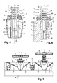
- the adjusting device 1 is constituted by the assembly of three distinct parts, namely: a base 2, a nut-wheel 3 and an adjusting rod 4.
- the rod 4 is held and guided in vertical translation in the base 2 and its maneuver in translation, upwards or downwards, is achieved by the nut-wheel 3 with which it cooperates with the intermediate suitable threads, so as to adjust the vertical level of its upper end which carries a support member 5 such as a batten or a tray, either directly or via a holding member 6 such that a batten tip (shown in dashed line on the figure 3 ).
- a support member 5 such as a batten or a tray
- a holding member 6 such that a batten tip (shown in dashed line on the figure 3 ).
- the base 2 consists of a plastic part provided here with two orifices 7 which allow its attachment to a support frame 8, for example on the vertical inner face of a bed frame spar.
- This base 2 comprises an upper housing 9 for receiving the nut-wheel 3, and a lower housing 10 in particular for receiving the lower part of the sliding rod 4.
- the upper housing 9 has an upper opening 11 and an opening lower 12; it also has peripheral windows, in particular a front window 13 framed by two side windows 13 '.
- the lower housing 10 On its side, the lower housing 10 has an upper portion 15 of generally cylindrical shape, and a lower portion 16, also of generally cylindrical shape, which are coaxial with each other, centered on a vertical axis 17.
- the lower part 16 of the housing 10 has a front opening 18 delimited in particular by an upper edge 19.
- this lower housing portion 16 has a vertical projecting lug 20 which extends in the median vertical plane of the housing 10 (parallel to the axis 17) and which is made in one piece with a rear plate 21.
- This rear plate 21 is shaped to come to press against the vertical face of the bed frame spar 8 and has, on its sides, the two orifices 7 mentioned above.
- the wheel-nut 3 consists of a plastic part in the general shape of a circular ring, the periphery of which is provided with striations 22 intended to facilitate its maneuver in rotation. Its central orifice 23 has a thread 24.
- the adjusting rod 4 consists of a plastic part of generally cylindrical shape. It comprises an upper portion 25 equipped with a thread 26 complementary to the thread 24 of the wheel-nut 3, and a lower portion 27 without threading. Its upper end is equipped with means 28 (here in the form of a simple plate), which allow the removable reception of a holding member 6 of the support element 5, for example, as illustrated in FIG. figure 3 , a tip 6 for receiving and suspending a slat 5.
- the lower portion 27 of the adjusting rod 4 has a rear longitudinal groove 29 (visible on the figure 6 ) intended to cooperate with the lug 20 of the base 2 to ensure the translational guidance of said rod 4 during the operation of the knob-nut 3.
- the lower portion of rod 27 comprises, on the front, an elastic tongue 30 intended to cooperate with the upper edge 19 above the front opening 18 made in the lower housing 10 of the base, to form a stop element (high stop) limiting the vertical extension of the rod 4.
- the adjusting device 1 is mounted by positioning the knob-nut 3 in its receiving housing 9, with its central orifice 23 placed opposite the upper and lower openings 11, 12, the axis of said orifice 23 being centered on the axis 17 of the lower housing 10 of the base 2. Part of the periphery of the wheel-nut 3 is then made operable by the front windows 13 or 13 'side. Then, the adjustment rod 4 is inserted through its lower end into the base 2, passing through the orifice 23 of the nut-wheel 3, until its upper thread 26 cooperates with the threading 24 of said nut wheel 3. Then, the nut-wheel 3 is rotated to initiate cooperation between the threads 24 and 26 and to ensure proper positioning of the lower portion of the rod 4 within its receiving housing 16. During this operation, the tongue 30 resiliently passes the level of the upper edge 19 of the opening 18 to be slightly protruding outwardly; on the other hand, the rear groove 29 of the rod 4 engages the protruding pin 20 of the base 2.
- the head 28 of the adjusting rod 4 protrudes above the base 2.
- the threaded upper portion 26 of this rod 4 passes through: - the upper orifice 11 of the housing 9, - the central orifice 23 of the nut-wheel 3 (with the thread 24 which it cooperates with), as well as - the lower orifice 12 of the housing 9; and it extends partially in the upper part 15 of the lower housing 10 of the base 2.
- This housing portion 15 is structured according to the dimensional characteristics of the threaded portion of rod 26, so as not to disturb the displacement in translation of the rod 4.
- the lower portion 27 of the rod 4 extends, according to its position, at least partially in the lower portion 16 of the base housing 10.
- This lower housing portion 16 advantageously has a generally cylindrical corresponding shape, with the clearance, to the external dimensions of the lower part of rod 27.
- This adjustment device 1 is positioned on its support frame 8 so that the axis of the adjustment rod 4 extends vertically or substantially vertically, this axis coinciding with the axis of rotation of the wheel-nut 3 and with the axis 17 of the base housing 10.
- the slats or trays 5 can be fixed directly on the head of the sliding rod 4, or by means of holding members 6 removably attached.
- the adjustment stroke can be of the order of a few centimeters (1 to 5 cm for example).
- This adjustment stroke is limited, downwards, by the abutment of the lower end of the rod 4 against the bottom of the base 2, or by the stop of the upper plate 28 against the upper part of the housing 9. Upwards, this stroke is limited by the elastic tongue 30 cooperating with the upper edge 19 of the front opening 18. It will be noted that the disassembly of the device is possible because of the elasticity characteristics of this tongue 30.
- the adjusting device 1 in which the upper end of the sliding rod 4 removably receives endpieces 6 of the double-slat type, for receiving two transverse slats 5.
- the base 2 of each device is carried by lateral arms 31 integral with rocker members 32 mounted on the bed frame 8.
- the height of the two-slat assemblies 5, 6 can thus be adjusted as desired (within the permissible adjustment range), this in a very simple and very fine manner, by simple rotation of the nut-wheel 3.
- the internal structure of the base 2 does not appear on the figure 7 , but it is similar to that of the previous embodiment, incorporating guide means in translation of the sliding rod 4, with or without high stop structure.
Landscapes
- Invalid Beds And Related Equipment (AREA)
- Special Chairs (AREA)
Applications Claiming Priority (1)
| Application Number | Priority Date | Filing Date | Title |
|---|---|---|---|
| FR0701640A FR2913322B1 (fr) | 2007-03-07 | 2007-03-07 | Dispositif de reglage du niveau vertical d'un element support de type latte ou plateau pour sommier ou siege |
Publications (3)
| Publication Number | Publication Date |
|---|---|
| EP1969973A2 true EP1969973A2 (de) | 2008-09-17 |
| EP1969973A3 EP1969973A3 (de) | 2008-10-08 |
| EP1969973B1 EP1969973B1 (de) | 2010-06-16 |
Family
ID=38828589
Family Applications (1)
| Application Number | Title | Priority Date | Filing Date |
|---|---|---|---|
| EP20080305051 Not-in-force EP1969973B1 (de) | 2007-03-07 | 2008-03-07 | Regulierungsvorrichtung der senkrechten Höhe eines Untergestellelements vom Typ Lattenrost oder Platte für Bettrahmen oder Sitz |
Country Status (3)
| Country | Link |
|---|---|
| EP (1) | EP1969973B1 (de) |
| DE (1) | DE602008001516D1 (de) |
| FR (1) | FR2913322B1 (de) |
Cited By (3)
| Publication number | Priority date | Publication date | Assignee | Title |
|---|---|---|---|---|
| EP2090196A3 (de) * | 2008-02-14 | 2009-10-21 | Diemer & Dr. Jaspert GbR | Federelement für eine Federkernmatratze oder eine Untermatratze oder als Randlager für ein Lattenrost sowie Randlager |
| US20110258772A1 (en) * | 2008-09-30 | 2011-10-27 | Frank Verschuere | Bed system |
| EP2392232A1 (de) * | 2010-06-03 | 2011-12-07 | Delahousse Et Fils | Sitz- oder Liegevorrichtung für Bettrahmen oder Sitzgestell |
Families Citing this family (1)
| Publication number | Priority date | Publication date | Assignee | Title |
|---|---|---|---|---|
| DE202010009239U1 (de) | 2010-06-18 | 2010-10-07 | Woeste, Peter, Dipl.-Kaufm. Dipl.-Designer | Stützvorrichtung für Liege- und Sitzelemente |
Family Cites Families (3)
| Publication number | Priority date | Publication date | Assignee | Title |
|---|---|---|---|---|
| DE3510971A1 (de) * | 1985-03-26 | 1986-10-09 | Metzeler Schaum Gmbh, 8940 Memmingen | Elastische halterung fuer die federlatten eines lattenrostes |
| DE4119723A1 (de) * | 1991-06-14 | 1992-12-17 | Dunlop Gmbh | Lattenrost |
| DE9301114U1 (de) * | 1993-01-27 | 1993-04-08 | Metzeler Schaum Gmbh, 8940 Memmingen | Lagerung für Federlatten eines Lattenrostes |
-
2007
- 2007-03-07 FR FR0701640A patent/FR2913322B1/fr not_active Expired - Fee Related
-
2008
- 2008-03-07 EP EP20080305051 patent/EP1969973B1/de not_active Not-in-force
- 2008-03-07 DE DE200860001516 patent/DE602008001516D1/de active Active
Cited By (5)
| Publication number | Priority date | Publication date | Assignee | Title |
|---|---|---|---|---|
| EP2090196A3 (de) * | 2008-02-14 | 2009-10-21 | Diemer & Dr. Jaspert GbR | Federelement für eine Federkernmatratze oder eine Untermatratze oder als Randlager für ein Lattenrost sowie Randlager |
| US20110258772A1 (en) * | 2008-09-30 | 2011-10-27 | Frank Verschuere | Bed system |
| US8918928B2 (en) * | 2008-09-30 | 2014-12-30 | Ls Bedding | Adjustable bed system |
| EP2392232A1 (de) * | 2010-06-03 | 2011-12-07 | Delahousse Et Fils | Sitz- oder Liegevorrichtung für Bettrahmen oder Sitzgestell |
| FR2960754A1 (fr) * | 2010-06-03 | 2011-12-09 | Delahousse Et Fils Sa | Dispositif d'assise ou de couchage pour chassis de sommier ou siege |
Also Published As
| Publication number | Publication date |
|---|---|
| FR2913322A1 (fr) | 2008-09-12 |
| EP1969973A3 (de) | 2008-10-08 |
| FR2913322B1 (fr) | 2009-06-05 |
| DE602008001516D1 (de) | 2010-07-29 |
| EP1969973B1 (de) | 2010-06-16 |
Similar Documents
| Publication | Publication Date | Title |
|---|---|---|
| EP0174884B1 (de) | Verstellbare Kopfstütze für Kraftwagensitze oder ähnliches | |
| EP2878481B1 (de) | Passagiersitz mit Schalensitzstruktur und einstellbarer Position | |
| EP0816163B1 (de) | Kindersitz mit bewegbaren Armlehnen | |
| EP1969973B1 (de) | Regulierungsvorrichtung der senkrechten Höhe eines Untergestellelements vom Typ Lattenrost oder Platte für Bettrahmen oder Sitz | |
| FR2916423A1 (fr) | Siege avec appui-tete pivotant | |
| FR2487270A1 (fr) | Dispositif pour le montage d'un appui-tete reglable en hauteur sur un siege d'automobile | |
| FR2596336A1 (fr) | Siege reglable pour vehicule automobile | |
| EP0458000B1 (de) | Kraftfahrzeugsitz | |
| FR2670101A1 (fr) | Perfectionnement aux dispositifs de suspension et de guidage de lattes pour sommier et sommier muni d'un tel dispositif. | |
| EP2030531A2 (de) | Aufhängevorrichtung für Matratzenrost und mit dieser Vorrichtung ausgerüsteter Bettrahmen | |
| FR2666973A1 (fr) | Curseur variateur de tension pour sommier a lattes. | |
| EP2151178B1 (de) | Vorrichtung zur Höhenregulierung der Stützteile eines Sitzes oder einer Matratze gegenüber einem Untergestell | |
| EP0410847A1 (de) | Halterungsvorrichtung für verstellbare Federung und Lagerung, insbesondere für Betten oder Sitze | |
| EP2965665A1 (de) | Aufhängevorrichtung mit federlatten für bed oder sitz | |
| FR2915068A1 (fr) | Dispositif de reglage de la flexibilite de latte(s)d'un sommier a latte(s)et sommier equipe d'un tel dispositif. | |
| FR2773760A1 (fr) | Poussette pour enfant, a hamac allongeable telescopique, et hamac correspondant | |
| EP1266594A1 (de) | Tisch mit eingebautem einschiebbarem Sitze | |
| EP1836934B1 (de) | Lagerungselement für Sprungrahmen oder Lattenrost, die mit Mitteln zur Stabilitätseinstellung versehen sind | |
| WO2016156620A1 (fr) | Dispositif amovible de stabilisation d'un fauteuil roulant ou similaire | |
| EP0281445A1 (de) | Verstellbarer und umlegbarer Sitz, insbesondere für Fahrzeuge | |
| EP3297899A1 (de) | Sattel mit einer längs und vertikal verstellbaren rückenlehne für schmales kraftfahrzeug | |
| FR2484807A1 (fr) | Dispositif de reglage de la position de l'assise d'un siege par rapport a son support | |
| FR2883144A1 (fr) | Dispositif pour le reglage en hauteur de traverses support de sommier et cadre de lit du type forme de longerons et de traverses reliant entre eux lesdits longerons | |
| FR2745245A1 (fr) | Appui-tete reglable | |
| FR2740669A1 (fr) | Element de tete de lit, respectivement de pied de lit |
Legal Events
| Date | Code | Title | Description |
|---|---|---|---|
| PUAI | Public reference made under article 153(3) epc to a published international application that has entered the european phase |
Free format text: ORIGINAL CODE: 0009012 |
|
| PUAL | Search report despatched |
Free format text: ORIGINAL CODE: 0009013 |
|
| AK | Designated contracting states |
Kind code of ref document: A2 Designated state(s): AT BE BG CH CY CZ DE DK EE ES FI FR GB GR HR HU IE IS IT LI LT LU LV MC MT NL NO PL PT RO SE SI SK TR |
|
| AX | Request for extension of the european patent |
Extension state: AL BA MK RS |
|
| AK | Designated contracting states |
Kind code of ref document: A3 Designated state(s): AT BE BG CH CY CZ DE DK EE ES FI FR GB GR HR HU IE IS IT LI LT LU LV MC MT NL NO PL PT RO SE SI SK TR |
|
| AX | Request for extension of the european patent |
Extension state: AL BA MK RS |
|
| 17P | Request for examination filed |
Effective date: 20090407 |
|
| AKX | Designation fees paid |
Designated state(s): BE DE FR |
|
| GRAP | Despatch of communication of intention to grant a patent |
Free format text: ORIGINAL CODE: EPIDOSNIGR1 |
|
| GRAS | Grant fee paid |
Free format text: ORIGINAL CODE: EPIDOSNIGR3 |
|
| GRAA | (expected) grant |
Free format text: ORIGINAL CODE: 0009210 |
|
| AK | Designated contracting states |
Kind code of ref document: B1 Designated state(s): BE DE FR |
|
| REF | Corresponds to: |
Ref document number: 602008001516 Country of ref document: DE Date of ref document: 20100729 Kind code of ref document: P |
|
| PLBE | No opposition filed within time limit |
Free format text: ORIGINAL CODE: 0009261 |
|
| STAA | Information on the status of an ep patent application or granted ep patent |
Free format text: STATUS: NO OPPOSITION FILED WITHIN TIME LIMIT |
|
| 26N | No opposition filed |
Effective date: 20110317 |
|
| REG | Reference to a national code |
Ref country code: DE Ref legal event code: R097 Ref document number: 602008001516 Country of ref document: DE Effective date: 20110316 |
|
| PGFP | Annual fee paid to national office [announced via postgrant information from national office to epo] |
Ref country code: FR Payment date: 20131203 Year of fee payment: 7 |
|
| PGFP | Annual fee paid to national office [announced via postgrant information from national office to epo] |
Ref country code: BE Payment date: 20131205 Year of fee payment: 7 |
|
| PGFP | Annual fee paid to national office [announced via postgrant information from national office to epo] |
Ref country code: DE Payment date: 20131205 Year of fee payment: 7 |
|
| REG | Reference to a national code |
Ref country code: DE Ref legal event code: R119 Ref document number: 602008001516 Country of ref document: DE |
|
| REG | Reference to a national code |
Ref country code: FR Ref legal event code: ST Effective date: 20151130 |
|
| PG25 | Lapsed in a contracting state [announced via postgrant information from national office to epo] |
Ref country code: DE Free format text: LAPSE BECAUSE OF NON-PAYMENT OF DUE FEES Effective date: 20151001 |
|
| PG25 | Lapsed in a contracting state [announced via postgrant information from national office to epo] |
Ref country code: FR Free format text: LAPSE BECAUSE OF NON-PAYMENT OF DUE FEES Effective date: 20150331 |
|
| PG25 | Lapsed in a contracting state [announced via postgrant information from national office to epo] |
Ref country code: BE Free format text: LAPSE BECAUSE OF NON-PAYMENT OF DUE FEES Effective date: 20150331 |