EP1970028B1 - Schutzbrille - Google Patents
Schutzbrille Download PDFInfo
- Publication number
- EP1970028B1 EP1970028B1 EP08003139A EP08003139A EP1970028B1 EP 1970028 B1 EP1970028 B1 EP 1970028B1 EP 08003139 A EP08003139 A EP 08003139A EP 08003139 A EP08003139 A EP 08003139A EP 1970028 B1 EP1970028 B1 EP 1970028B1
- Authority
- EP
- European Patent Office
- Prior art keywords
- lens frame
- front surface
- connection
- goggles
- pivot
- Prior art date
- Legal status (The legal status is an assumption and is not a legal conclusion. Google has not performed a legal analysis and makes no representation as to the accuracy of the status listed.)
- Ceased
Links
- 229920003002 synthetic resin Polymers 0.000 claims description 8
- 239000000057 synthetic resin Substances 0.000 claims description 8
- 230000008878 coupling Effects 0.000 description 6
- 238000010168 coupling process Methods 0.000 description 6
- 238000005859 coupling reaction Methods 0.000 description 6
- 230000000284 resting effect Effects 0.000 description 5
- 230000000630 rising effect Effects 0.000 description 5
- 239000004744 fabric Substances 0.000 description 2
- 238000009423 ventilation Methods 0.000 description 2
- 239000004925 Acrylic resin Substances 0.000 description 1
- 229920000178 Acrylic resin Polymers 0.000 description 1
- 229920000122 acrylonitrile butadiene styrene Polymers 0.000 description 1
- 238000005452 bending Methods 0.000 description 1
- 230000001419 dependent effect Effects 0.000 description 1
- 230000002542 deteriorative effect Effects 0.000 description 1
- 239000000428 dust Substances 0.000 description 1
- 230000000694 effects Effects 0.000 description 1
- 230000001939 inductive effect Effects 0.000 description 1
- 230000009545 invasion Effects 0.000 description 1
- 239000005871 repellent Substances 0.000 description 1
- 230000000717 retained effect Effects 0.000 description 1
- 229920002803 thermoplastic polyurethane Polymers 0.000 description 1
Images









Classifications
-
- A—HUMAN NECESSITIES
- A61—MEDICAL OR VETERINARY SCIENCE; HYGIENE
- A61F—FILTERS IMPLANTABLE INTO BLOOD VESSELS; PROSTHESES; DEVICES PROVIDING PATENCY TO, OR PREVENTING COLLAPSING OF, TUBULAR STRUCTURES OF THE BODY, e.g. STENTS; ORTHOPAEDIC, NURSING OR CONTRACEPTIVE DEVICES; FOMENTATION; TREATMENT OR PROTECTION OF EYES OR EARS; BANDAGES, DRESSINGS OR ABSORBENT PADS; FIRST-AID KITS
- A61F9/00—Methods or devices for treatment of the eyes; Devices for putting in contact-lenses; Devices to correct squinting; Apparatus to guide the blind; Protective devices for the eyes, carried on the body or in the hand
- A61F9/04—Eye-masks ; Devices to be worn on the face, not intended for looking through; Eye-pads for sunbathing
-
- A—HUMAN NECESSITIES
- A61—MEDICAL OR VETERINARY SCIENCE; HYGIENE
- A61F—FILTERS IMPLANTABLE INTO BLOOD VESSELS; PROSTHESES; DEVICES PROVIDING PATENCY TO, OR PREVENTING COLLAPSING OF, TUBULAR STRUCTURES OF THE BODY, e.g. STENTS; ORTHOPAEDIC, NURSING OR CONTRACEPTIVE DEVICES; FOMENTATION; TREATMENT OR PROTECTION OF EYES OR EARS; BANDAGES, DRESSINGS OR ABSORBENT PADS; FIRST-AID KITS
- A61F9/00—Methods or devices for treatment of the eyes; Devices for putting in contact-lenses; Devices to correct squinting; Apparatus to guide the blind; Protective devices for the eyes, carried on the body or in the hand
- A61F9/02—Goggles
- A61F9/027—Straps; Buckles; Attachment of headbands
-
- A—HUMAN NECESSITIES
- A61—MEDICAL OR VETERINARY SCIENCE; HYGIENE
- A61F—FILTERS IMPLANTABLE INTO BLOOD VESSELS; PROSTHESES; DEVICES PROVIDING PATENCY TO, OR PREVENTING COLLAPSING OF, TUBULAR STRUCTURES OF THE BODY, e.g. STENTS; ORTHOPAEDIC, NURSING OR CONTRACEPTIVE DEVICES; FOMENTATION; TREATMENT OR PROTECTION OF EYES OR EARS; BANDAGES, DRESSINGS OR ABSORBENT PADS; FIRST-AID KITS
- A61F9/00—Methods or devices for treatment of the eyes; Devices for putting in contact-lenses; Devices to correct squinting; Apparatus to guide the blind; Protective devices for the eyes, carried on the body or in the hand
- A61F9/02—Goggles
Definitions
- the present invention relates to goggles that a user can use in either case of wearing a helmet or not.
- a user sometimes wears goggles on a helmet in case of sport such as a ski competition and work such as electric work, civil work and the like which require a helmet.
- sport such as a ski competition
- work such as electric work, civil work and the like which require a helmet.
- a helmet competition whether wearing a helmet or not mainly depends on sliding speeds of various races.
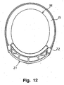
- a lens frame 21 is rather wide laterally in a front view and has a large thickness, as shown in Fig. 12 .
- the frame of the goggles is designed to match with the thickness of the helmet. Due to this large thickness, when a user wears the goggles directly on his head, the goggles give less fitted comfortability to his face than general goggles not designed for use on a helmet.
- numeral 22 denotes a wearing belt
- character R denotes an interior liner
- character M denotes a head of a person.
- contestants play in plural races, especially in severe sports in which the fitted comfortability of the goggles to their faces and the functions of them are crucial factors and directly affect the results, the contestants must have plural pairs of goggles suitable to helmets depending on respective races.
- goggles described above are for skiing. Since goggles for motocross, goggles for other sports, and goggles for various kinds of work are also required fitted comfortability to a wearer's face, they have the same problem.
- goggles that can give a wearer a suitable fitted comfortability to his face regardless of whether a helmet is used or not, and regardless of the thickness of an interior liner of the helmet have been provided.
- the goggles include arms 23 of soft-type elastic synthetic resin which are formed as one body with a lens frame 21 and project from the projecting positions on the right and left parts of the upper and lower parts of the lens frame 21.
- Each of the arms 23 has an end in the vicinity of a belt coupling position apart from the above projecting position, and connected to a stretch elastic belt 25 in the vicinity of that end through a belt connecting part 24.
- the arm 23 is elastically deformed to overlap with at least one part of a front surface of the lens frame 21, or to roughly extend along and in front of the front surface.
- Japanese Unexamined Patent Publication No. 10-229998 page 2, Figs. 1 , 5 , 7 and 8 ).
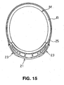
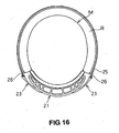
- the goggles with the above structure are shown in Fig. 15 . It is described that when a user wears the goggles on a helmet with a thin interior liner R, the restoring force of the stretch elastic belt 25 is converted to a pressure of the goggles to the wearer's face, the force rising from the wearer's face is not generated. It is also described that, as shown in Fig. 16 , when a user wears the goggles on a helmet with a thick interior liner R, the force rising from the user's face is not generated, either. Further it is described that as shown in Fig.
- Document US-A 2003/0,101,507 relates to a goggle having at least one side arm.
- the arm may be used to support a goggle on a wearer's head and may be pivotally mounted to the goggle frame inward of an outermost portion of the goggle lens(es) or frame.
- EPC discloses a sports goggle having generally U-shaped attachment arms at opposite sides of a google frame for securing the google frame to an elastic headband.
- the attachment arms are secured to the google frame at locations inward from the sides of the frame.
- the invention relates to googles comprising a lens frame and connection arms for a wearing belt as claimed in the independent claims 1, 2 and 3.
- Goggles according to the present invention include connection arms of a wearing belt on a side of a front surface of right and left parts of a lens frame.
- the connection arms are kept selectively in one of states that each of the arms overlaps and rests on the front surface of the lens frame and that each of the connection arms stays at a position with a space from the front surface of the lens frame after having moved rotationally on its inner end from the front surface of the lens frame outwardly.
- the goggles according to the present invention further include a pivot hole, an engagement hole and an abutment part on each of upper and lower parts on the side of the front surface of the right and left parts of the lens frame, and a pivot part, an engagement part and an abutting part on an inner end part of each of the connection arms.
- the pivot part of the connection arm is pivotally supported in the pivot hole of the lens frame, and the engagement part of the connection arm is engaged with the engagement hole of the lens frame, so as to keep each of the connection arms overlapping and resting on the front surface of the lens frame.
- connection arm is pivotally supported in the pivot hole of the lens frame, the engagement part of the connection arm is engaged with the front surface of the lens frame, and furthermore the abutting part of the connection arm touches the abutment part of the lens frame to be positioned there.
- each of the connection arms is kept staying there with a space from the front surface of the lens frame after having moved rotationally on its inner end part from the front surface of the lens frame outwardly.
- the goggles according to the present invention may include a pivot part, an engagement hole and an abutment part on each of upper and lower parts on a side of a front surface of right and left parts of a lens frame, and a pivot hole, an engagement part and an abutting part on an inner end part of the each of the connection arms.
- the pivot hole of the connection arm pivotally supports the pivot part of the lens frame, and the engagement part of the connection arm is engaged with the engagement hole of the lens frame, so that each of the connection arms is kept in a state in which the connection arm overlaps and rests on the front surface of the lens frame.
- the pivot hole of the connection arm pivotally supports the pivot part of the lens frame, the engagement part of the connection arm engages with the front surface of the lens frame, and further the abutting part of the connection arm touches the abutment part of the lens frame to be positioned there, so that each of the connection arms is kept in a state in which the connection arm stays there with a space from the front surface of the lens frame after having moved rotationally on its inner end side from the side of the front surface of the lens frame outwardly.
- the pivot hole of the lens frame penetrates the lens frame, and a tip end of the pivot part of the connection arm is provided with a retaining part to prevent removal from the pivot hole.
- the pivot hole of the connection arm may penetrate the connection arm, and a tip end of the pivot part of the lens frame is provided with a retaining part to prevent removal from the pivot hole.
- the pivot hole and the engagement hole of the lens frame are provided in a recess part formed on each of the upper and lower parts of the right and left parts of the lens frame, and the recess part receives the inner end part of the connection arm.
- the pivot part and the engagement hole of the lens frame may be provided in a recess part which is formed on each of the upper and lower parts of the right and left parts of the lens frame and receives the inner end part of the connection arm.
- connection arms protrude out from the right and left parts of the lens frame.
- each of the connection arms has a rotational angle of a range of 15 to 22 degrees in which the connection arm moves rotataionally on its inner end side from the front surface of the lens frame outwardly.
- the lens frame of the goggles according to the present invention is formed of soft-type elastic synthetic resin and the connection arms are formed of hard-type elastic synthetic resin.
- the goggles of the present invention provide a preferable fitted comfortability to a wear's face regardless of whether a helmet is used or not and regardless of the thickness of an interior liner of a helmet.
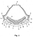
- Figs. 1 to 7 show one embodiment of the goggles of the present invention.
- Connection arms 3 for a wearing belt 2 are detachably mounted on parts of a front surface 1c of right and left parts 1a and 1b of a lens frame 1.
- the lens frame 1 is detachably or fixedly provided with a lens 4 made of an acrylic resin plate and the like, and has a ventilation part 5 on an upper part and/or other appropriate parts so as to prevent the lens 4 from fogging.
- the lens frame 1 is formed of soft-type elastic synthetic resin such as urethane resin.
- the lens frame 1 is provided with a sponge pad 6 on the side of a rear surface 1d (the side to be in contact with a wearer's face).
- the ventilation part 5 is covered with a cloth 7 or the like made of a water-repellent mesh fabric so as to prevent snow or dust and the like from entering the inside of the goggles.
- the wearing belt 2 is made up with two detachable parts through a buckle 8 at the center of the belt, and both end parts of the belt are connected to respective outer end parts 3a of the connection arms 3. Furthermore, length adjusters 9 are mounted on near the both end parts of the belt.
- the wearing belt 2 is preferably an elastic belt, but not limitative thereto, and it may be a non-elastic one.
- connection arms 3 preferably have configurations corresponding to respective shapes of the right and left parts 1a and 1b of the lens frame 1.
- each of the arms has a roughly U-shaped configuration in which upper part and lower part continue in one body, but the arm may be made up with an upper part and a lower part separately.
- the connection arms 3 can be mounted on the side of the front surface 1c of the right and left parts 1a and 1b of the lens frame 1 and the wearing belt 2 can be connected therewith, the shape of the connection arm is not limitative.
- the connection arm 3 is formed of hard-type elastic synthetic resin such as an ABS resin, not to be easily deformed by bending.
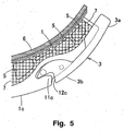
- connection arms 3 can be kept selectively in either state that it overlaps and rests on the front surface 1c of the lens frame 1 as shown in Fig. 5 , or that it stays at a position having a space S from the front surface 1c of the lens frame 1 after having moved rotationally on a side of an inner end 3b from the front surface 1c of the lens frame 1 outwardly as shown in Fig. 7 .
- Changing the mode of the connection arm from the state in Fig. 5 to that in Fig. 7 requires removal of the connection arm 3 off the lens frame 1. Since the lens frame 1 is formed of soft-type elastic synthetic resin, the connection arm 3 can be moved off by elastically deforming the lens frame 1.
- connection arm 3 in order to keep each of the connection arms 3 overlapping and resting on the front surface 1c of the lens frame 1, upper part and lower part 1e and 1f on the side of the front surface 1c of the left and the right parts 1a and 1b of the lens frame 1 (as shown in Figs 1 and 2 ) are respectively provided with a pivot hole 11a, an engagement hole 11b and an abutment part 11c, as shown in Figs. 4 and 5 .
- the inner end part 3b of the connection arm 3 is provided with a pivot part 12a for the pivot hole 11a, an engagement part 12b for the engagement hole 11b, and an abutting part 12c for the abutment part 11c.
- the pivot part 12a of the connection arm 3 is engaged with the pivot hole 11 a of the lens frame 1 and the engagement part 12b of the connection arm 3 is engaged with the engagement hole 11b of the lens frame 1.
- the pivot part 12a of the connection arm 3 is engaged with the pivot hole 11a of the lens frame 1
- the engagement part 12b of the connection arm 3 is engaged with the front surface 1c of the lens frame 1
- the abutment part 12c of the connection arm 3 abuts on the abutment part 11c of the lens frame 1.
- the pivot hole 11a of the lens frame 1 penetrates the lens frame 1 and a tip end of the pivot part 12a of the connection arm 3 is provided with a retaining part 13 with respect to the pivot hole 11a.
- the abutment part 11c of the lens frame 1 has a convex shape while the abutting part 12c of the connection arm 3 has a concave shape, but not limitative thereto and they may be shaped reversely.
- the pivot hole 11a and the engagement hole 11 b of the lens frame 1 are formed in a recess part 10 provided each on at the upper and lower parts 1e and 1f of the right and left parts 1a and 1b of the lens frame 1 and the recess part 10 receives the inner end part 3b of the connection arm 3.
- each of the connection arms 3 does not protrude from the upper and lower parts 1e and 1f of the right and left parts 1a and 1b of the lens frame 1 but flushes with the upper and lower parts 1e and 1f.
- the connection arm 3 therefore does not stand as an obstacle and thereby air resistance becomes low. Therefore, the goggles according to the present invention become suitable for goggles for various types of work as well as sporting goggles.
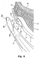
- connection arm 3 is needed to be kept in a state in which it overlaps and rests on the front surface 1c of the lens frame 1 is shown in fig. 8 .
- Each of the upper and lower parts 1e and 1f on the side of the front surface 1c of the right and left parts 1a and 1b of the lens frame 1 is provided with the pivot part 11d, the engagement hole 11b and the abutment part 11c, and the inner end part 3b of each of the connection arms 3 is provided with the pivot hole 12d for the pivot part 11d, an engagement part 12b for the engagement hole 11b, and an abutting part 12c for the abutment part 11c.
- the pivot hole 12d of the connection arm 3 is engaged with the pivot part 11d of the lens frame 1 and the engagement part 12b of the connection arm 3 is engaged with the engagement hole 11b of the lens frame 1.
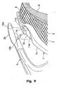
- connection arm 3 is needed to be maintained in a state in which, after having moved rotationally on the inner end part 3b from the front surface 1c of the lens frame 1 outwardly, the connection arm 3 stays at a position with a space S from the front surface 1, is shown in Fig. 9 .
- the connection arm 3 is to be positioned where the pivot hole 12d of the connection arm 3 is engaged with the pivot part 11d of the lens frame 1, the engagement part 12b of the connection arm 3 abuts the front surface 1c of the lens frame 1, and the abutment part 12c of the connection arm 3 abuts the abutment part 11c of the lens frame 1.
- connection arm 3 penetrates the connection arm3 and a tip end of the pivot part 11d of the lens frame 1 is provided with a retaining part 14 to be retained in the pivot hole 12d of the connection arm 3.
- the connection arm 3 is unlikely to remove off the lens frame 1, so that the connection arm 3 can be reliably mounted on the lens frame 1.
- the abutment part 11c of the lens frame 1 has a convex shape while the abutting part 12c of the connection arm 3 has a concave shape, but not limitative thereto and they may be shaped reversely.
- the pivot parts 11d and the engagement holes 11 b of the lens frame 1 are formed in the recess parts 10 formed respectively at the upper and lower parts 1e and 1 of the right and left parts 1 a and 1b of the lens frame 1, and the recess parts 10 receives the inner end parts 3b of the connection arms.
- the connection arms 3 do not protrude from the upper and lower parts 1e and 1f of the right and left parts 1a and 1b of the lens frame 1, but flush with the upper and lower parts 1e and 1f.
- the goggles can be preferably used as goggles for various types of work and for sports.
- each of the outer end parts 3a of the connection arms 3 protrudes from the right and left parts 1a and 1b of the lens frame 1.
- the belt end parts connected to the outer end parts 3a of the connection arms 3 are prevented from abutting the lens frame 1 and being lifted up. Therefore, the connection arms 3 can be kept overlapping on the front surface 1c of the lens frame 1 without rising up and separating therefrom.
- an angle wherein each of the connection arms 3 moves rotationally on the side of the inner end part 3b from the side of the front surface 1c of the lens frame 1 outwardly is set within a range of 15 to 22 degrees.
- a rotating angle smaller than 15 degrees is not preferable because, in the case where an inner liner R of a helmet is thick, the outer end part 3a of the connection arm 3 could abut on an opening end 15 of the inner liner R.
- a rotating angle larger than 22 degrees is not preferable, either, because the outer end part 3a of the connection arm 3 comes into view of a goggle wearer and narrows his sight.
- connection arm 3 when a rotational center of each of the connection arms 3 is set at a position provided by dividing the lens frame 1 lengthwise into three equal parts, tensile force of the connection arm 3 by the wearing belt 2 can be applied to the entire frame in balance, which provides a stable comfortability to a wearer.
- the rotational angle of the connection arm 3 can be variously adjusted within the above range. This can be realized by providing a plurality of engagement holes 11 b on the upper and lower parts 1e and 1f on the side of the front surface 1c of the right and left parts 1a and 1b of the lens frame 1.
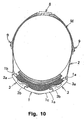
- the goggles according to the present invention being constituted as stated above, a wearer can have a preferable fitted comfortability to his face when wearing it directly on his head M as shown in Fig. 10 .
- a wearer can have a preferable fitted comfortability to his face when wearing it directly on his head M as shown in Fig. 10 .
- each of the connection arms 3 is pulled by the wearing belt 2 and force to lift the goggles up from the his face does not work.
- connection arms 3 when each of the connection arms 3 is kept staying at the position with a space S after having moved rotationally on the side of the inner end part 3b from the side of the front surface 1 c of the lens frame 1 outwardly, he can obtain a preferable comfortabiltiy to his face. Because the outer end 3a of the connection arm 3 does not abut the opening end 15 of a thick inner liner R, the connection arm 3 is pulled by the wearing belt 2 and force to lift the goggles up from his face does not work.
- the goggles according to the present invention can provide a suitable fitted comfortabilty to a wearer's face regardless of whether he uses a helmet or not and regardless of the thickness of the inner liner.
- the goggles according to the present invention has the structure stated above, a manufacturer of goggles can make the goggles to be used not only when using no helmet where the connection arms 3 are kept overlapping and resting on the front surface 1c of the lens frame 1, but also when using a helmet where the connection arms 3 are kept staying at a position with a space S after having moved rotationally on the side of the inner end part 32 from the side of the front surface 1c of the lens frame 1.
- goggles of the present invention by producing one type for goggles, goggle manufacturers can sell them as two types of goggles: one for use on a helmet and the other for use without a helmet, which results in reducing development and production cost.
Landscapes
- Health & Medical Sciences (AREA)
- Ophthalmology & Optometry (AREA)
- Engineering & Computer Science (AREA)
- Biomedical Technology (AREA)
- Heart & Thoracic Surgery (AREA)
- Vascular Medicine (AREA)
- Life Sciences & Earth Sciences (AREA)
- Animal Behavior & Ethology (AREA)
- General Health & Medical Sciences (AREA)
- Public Health (AREA)
- Veterinary Medicine (AREA)
- Eyeglasses (AREA)
Claims (10)
- Brille, umfassend einen Linsen-Rahmen (1) und Verbindungs-Arme (3) für ein Trage-Band (2), wobei die Arme (3) jeweils an einem rechten und linken Teil (1a, 1b) auf einer Seite der vorderen Fläche (1c) des Linsen-Rahmens (1) vorgesehen sind, worin jeder der Verbindungs-Arme (3) selektiv in einer der Lagen (a) und (b) gehalten ist:(a) dass der Arm (3) mit der vorderen Fläche (1c) des Linsen-Rahmens (1) überlappt und auf dieser ruht; und(b) dass der Arm (3) in einer Position mit einem Abstand (S) von der vorderen Fläche (1c) des Linsen-Rahmens (1) bleibt, nachdem er sich rotationsweise an seinem inneren Ende (3b) von der vorderen Fläche (1c) des Linsen-Rahmens (1) nach außen bewegt hat;wobei die Brille weiter umfaßt: eine Dreh-Öffnung (11a), eine Eingriffs-Öffnung (11b) und ein Stütz-Teil (11c) an jedem der oberen und unteren Teile (1e, 1f) an dem rechten und an dem linken Teil (1a, 1b) auf der Seite der vorderen Fläche (1c) des Linsen-Rahmens (1), sowie einen Dreh-Zapfen (12a), ein Eingriffs-Teil (12b) und ein Stütz-Teil (12c) an dem Innenend-Teil (3b) jedes der Verbindungs-Arme (3), worin der Dreh-Zapfen (12a) des Verbindungs-Arms (3) drehweise in der Dreh-Öffnung (11a) des Linsen-Rahmens (1) gelagert ist und das Eingriffs-Teil (12b) des Verbindungs-Arms (3) mit dem Eingriffs-Loch (11b) des Linsen-Rahmens (1) im Eingriff steht und so jeden der Verbindungs-Arme (3) in der Lage (a) hält.
- Brille, umfassend einen Linsen-Rahmen (1) und Verbindungs-Arme (3) für ein Trage-Band (2), wobei die Arme (3) jeweils an einem rechten und linken Teil (1a, 1b) auf einer Seite der vorderen Fläche (1c) des Linsen-Rahmens (1) vorgesehen sind, worin jeder der Verbindungs-Arme (3) selektiv in einer der Lagen (a) und (b) gehalten ist:(a) dass der Arm (3) mit der vorderen Fläche (1c) des Linsen-Rahmens (1) überlappt und auf dieser ruht; und(b) dass der Arm (3) in einer Position mit einem Abstand (S) von der vorderen Fläche (1c) des Linsen-Rahmens (1) bleibt, nachdem er sich rotationsweise an seinem inneren Ende (3b) von der vorderen Fläche (1c) des Linsen-Rahmens (1) nach außen bewegt hat;wobei die Brille weiter umfaßt: eine Dreh-Öffnung (11a), eine Eingriffs-Öffnung (11b) und ein Stütz-Teil (11c) an jedem der oberen und unteren Teile (1e, 1f) an dem rechten und an dem linken Teil (1a, 1b) auf der Seite der vorderen Fläche (1c) des Linsen-Rahmens (1), sowie einen Dreh-Zapfen (12a), ein Eingriffs-Teil (12b) und ein Stütz-Teil (12c) an dem Innenend-Teil (3b) jedes der Verbindungs-Arme (3), worin der Dreh-Zapfen (12a) des Verbindungs-Arms (3) drehweise in der Dreh-Öffnung (11a) des Linsen-Rahmens (1) gelagert ist, das Eingriffs-Teil (12b) des Verbindungs-Arms (3) mit der vorderen Fläche (1c) des Linsen-Rahmens (1) im Eingriff ist, und weiter das Stütz-Teil (12c) des Verbindungs-Arms (3) das Stütz-Teil (11c) des Linsen-Rahmens (1) berührt und dort positioniert ist, so dass jeder der Verbindungs-Arme (3) in der Lage (b) gehalten wird.
- Brille, umfassend einen Linsen-Rahmen (1) und Verbindungs-Arme (3) für ein Trage-Band (2), wobei die Arme (3) jeweils an einem rechten und linken Teil (1a, 1b) auf einer Seite der vorderen Fläche (1c) des Linsen-Rahmens (1) vorgesehen sind, worin jeder der Verbindungs-Arme (3) selektiv in einer der Lagen (a) und (b) gehalten ist:(a) dass der Arm (3) mit der vorderen Fläche (1c) des Linsen-Rahmens (1) überlappt und auf dieser ruht; und(b) dass der Arm (3) in einer Position mit einem Abstand (S) von der vorderen Fläche (1c) des Linsen-Rahmens (1) bleibt, nachdem er sich rotationsweise an seinem inneren Ende (3b) von der vorderen Fläche (1c) des Linsen-Rahmens (1) nach außen bewegt hat;wobei die Brille weiter umfaßt: einen Dreh-Zapfen (11d), eine Eingriffs-Öffnung (11b) und ein Stütz-Teil (11c) an jedem der oberen und unteren Teile (1e, 1f) an dem rechten und an dem linken Teil (1a, 1b) auf der Seite der vorderen Fläche (1c) des Linsen-Rahmens (1), sowie eine Dreh-Öffnung (12d), ein Eingriffs-Teil (12b) und ein Stütz-Teil (12c) an dem Innenend-Teil (3b) jedes der Verbindungs-Arme (3), worin der Verbindungs-Arm (3) selektiv in einer der Lagen (a) und (b) gehalten wird, wobei die Dreh-Öffnung (12d) des Verbindungs-Arms (3) rotationsweise den Dreh-Zapfen (11d) des Linsen-Rahmens (1) lagert und das Eingriffs-Teil (12b) des Verbindungs-Arms (3) mit dem Eingriffs-Loch (11b) des Linsen-Rahmens (1) im Eingriff steht und so jeden der Verbindungs-Arme (3) in der Lage (a) hält, und worin die Dreh-Öffnung (12d) des Verbindungs-Arms (3) rotationsweise den Dreh-Zapfen (11d) des Linsen-Rahmens (1) lagert, das Eingriffs-Teil (12b) des Verbindungs-Arms (3) mit der vorderen Fläche (1c) des Linsen-Rahmens (1) im Eingriff steht, und weiter das Stütz-Teil (12c) des Verbindungs-Arms (3) das Stütz-Teil (11c) des Linsen-Rahmens (1) berührt und dort positioniert ist, so dass jeder der Verbindungs-Arme (3) in der Lage (b) gehalten wird.
- Brille nach Anspruch 1 oder 2, worin die Dreh-Öffnung (11a) des Linsen-Rahmens (1) den Linsen-Rahmen (1) durchdringt und der Verbindungs-Arm (3) ein Halte-Teil (13) an einem Spitzen-End-Teil des Dreh-Zapfens (12a) zum Verhindern eines Entfernens von der Dreh-Öffnung (11a) aufweist.
- Brille nach Anspruch 3, worin die Dreh-Öffnung (12d) des Verbindungs-Arms (3) den Verbindungs-Arm (3) durchdringt und der Linsen-Rahmen (1) ein Halte-Teil (14) an einem Spitzen-End-Teil des Dreh-Zapfens (11d) zum Verhindern eines Entfernens von der Dreh-Öffnung (12d) aufweist.
- Brille nach Anspruch 1 oder 2, weiter umfassend ein Ausnehmungs-Teil (10) jeweils an den oberen und unteren Teilen (1e, 1f) des rechten Teils und des linken Teils (1a, 1b) des Linsen-Rahmens (1), worin das Ausnehmungs-Teil (10) mit der Dreh-Öffnung (11a) und der Eingriffs-Öffnung (11b) des Linsen-Rahmens (1) versehen ist und das innere End-Teil (3b) des Verbindungs-Arms (3) aufnimmt.
- Brille nach Anspruch 3, weiter umfassend ein Ausnehmungs-Teil (10) jeweils an den oberen und unteren Teilen (1e, 1f) des rechten Teils und des linken Teils (1a, 1b) des Linsen-Rahmens (1), worin das Ausnehmungs-Teil (10) mit dem Dreh-Zapfen (11d) und der Eingriffs-Öffnung (11b) des Linsen-Rahmens (1) versehen ist und das innere End-Teil (3b) des Verbindungs-Arms (3) aufnimmt.
- Brille nach irgendeinem der Ansprüche 1 bis 7, worin jeder der Verbindungs-Arme (3) von dem rechten und dem linken Teil (1a, 1b) des Linsen-Rahmens (1) heraussteht.
- Brille nach irgendeinem der Ansprüche 1 bis 8, worin jeder der Verbindungs-Arme (3) einen Drehwinkel eines Bereichs von 15 bis 22 Grad aufweist, worin sich der Verbindungs-Arm (3) rotationsweise auf der Innenend-Seite (3b) von der vorderen Fläche (1c) des Linsen-Rahmens (1) nach außen bewegt.
- Brille nach irgendeinem der Ansprüche 1 bis 9, worin der Linsen-Rahmen (1) gebildet ist aus einem synthetischen Harz des weichen, elastischen Typs und die Verbindungs-Arme (3) gebildet sind aus einem synthetischen Harz des harten, elastischen Typs.
Applications Claiming Priority (1)
| Application Number | Priority Date | Filing Date | Title |
|---|---|---|---|
| JP2007039361A JP4775659B2 (ja) | 2007-02-20 | 2007-02-20 | ゴーグル |
Publications (2)
| Publication Number | Publication Date |
|---|---|
| EP1970028A1 EP1970028A1 (de) | 2008-09-17 |
| EP1970028B1 true EP1970028B1 (de) | 2011-05-11 |
Family
ID=39667223
Family Applications (1)
| Application Number | Title | Priority Date | Filing Date |
|---|---|---|---|
| EP08003139A Ceased EP1970028B1 (de) | 2007-02-20 | 2008-02-20 | Schutzbrille |
Country Status (4)
| Country | Link |
|---|---|
| US (1) | US7895679B2 (de) |
| EP (1) | EP1970028B1 (de) |
| JP (1) | JP4775659B2 (de) |
| KR (1) | KR101420440B1 (de) |
Families Citing this family (19)
| Publication number | Priority date | Publication date | Assignee | Title |
|---|---|---|---|---|
| US20080256688A1 (en) * | 2007-04-18 | 2008-10-23 | Nike, Inc. | Article of Eyewear |
| WO2010068165A1 (en) * | 2008-12-10 | 2010-06-17 | Poc Sweden Ab | Protective eyewear with exchangable lens and strap |
| US8166578B2 (en) * | 2009-03-10 | 2012-05-01 | Kingman International Corporation | Goggle with quick release double locking lens |
| JP5418814B2 (ja) * | 2009-03-13 | 2014-02-19 | 山本光学株式会社 | ゴーグル |
| FR2959121B1 (fr) * | 2010-04-22 | 2013-01-18 | Salomon Sas | Masque de protection pour la pratique de sports de plein air. |
| CN102091411A (zh) * | 2010-12-30 | 2011-06-15 | 张亚兵 | 搏击运动护目镜 |
| TWM424508U (en) * | 2011-10-20 | 2012-03-11 | Borrion Entpr Co Ltd | Ski goggle structure |
| US20150143619A1 (en) * | 2013-11-26 | 2015-05-28 | Adam Paul Cross | Lens assembly |
| JP6118770B2 (ja) * | 2014-08-29 | 2017-04-19 | 株式会社タバタ | ゴーグル |
| US20160327810A1 (en) * | 2014-11-26 | 2016-11-10 | Adam Paul Cross | Lens assembly |
| WO2017069779A1 (en) * | 2015-10-23 | 2017-04-27 | Abominable Labs, Llc | Goggle interchangeable strap and clip system |
| USD812128S1 (en) * | 2016-06-28 | 2018-03-06 | Sagi Levi | Lighting spectacles |
| US20180289547A1 (en) * | 2017-04-07 | 2018-10-11 | Shenzhen Pengyifa Precision Mould Co., Ltd | Ski goggles with replaceable nose bridge support |
| USD837870S1 (en) * | 2017-06-12 | 2019-01-08 | Goalfix Sports Limited | Eye shades |
| USD919696S1 (en) * | 2019-07-18 | 2021-05-18 | Guangzhou Dexin Sport Googs Co., Ltd. | Sports goggles |
| USD906407S1 (en) * | 2019-08-28 | 2020-12-29 | Oakley, Inc. | Goggle |
| USD906406S1 (en) * | 2019-08-28 | 2020-12-29 | Oakley, Inc. | Goggle |
| KR102313737B1 (ko) * | 2020-01-10 | 2021-10-18 | 주식회사 스포컴 | 통기구를 구비하고 밴드의 탈부착이 가능한 고글 |
| CN223555069U (zh) * | 2024-11-15 | 2025-11-18 | 青岛奥技科光学有限公司 | 一种便于更换透气海绵的护目镜结构 |
Family Cites Families (11)
| Publication number | Priority date | Publication date | Assignee | Title |
|---|---|---|---|---|
| JPS57186514A (en) * | 1981-05-12 | 1982-11-17 | Nissan Motor Co Ltd | Air conditioning device for automobile |
| JP3646212B2 (ja) * | 1997-02-19 | 2005-05-11 | 山本光学株式会社 | ゴーグル |
| US6105177A (en) | 1997-12-26 | 2000-08-22 | Paulson Manufacturing Corp. | Protective goggles |
| US6047410A (en) * | 1998-08-03 | 2000-04-11 | Eye Safety Systems, Inc. | Goggle frame and attachment system |
| US6732383B2 (en) | 2001-12-03 | 2004-05-11 | The Burton Corporation | Goggle with side arm for wearing with a helmet |
| US6923537B2 (en) * | 2002-08-09 | 2005-08-02 | Gentex Corporation | Eyewear for ballistic and light protection |
| JP2005128426A (ja) * | 2003-10-27 | 2005-05-19 | Midori Anzen Co Ltd | 防塵眼鏡 |
| US7181779B2 (en) | 2004-01-23 | 2007-02-27 | K-2 Corporation | Sport goggle with side vent for improved ventilation |
| FR2883160B1 (fr) | 2005-03-18 | 2007-10-19 | Cebe Sa | Masque, notamment pour la pratique des sports de glisse |
| US7797765B2 (en) * | 2005-12-30 | 2010-09-21 | Bell Sports, Inc. | Lens replacement system |
| US20070250994A1 (en) | 2006-01-18 | 2007-11-01 | Mcneal Joseph R | Goggle having flexible headband attachment arms fixedly attached to a goggle frame |
-
2007
- 2007-02-20 JP JP2007039361A patent/JP4775659B2/ja active Active
-
2008
- 2008-02-20 EP EP08003139A patent/EP1970028B1/de not_active Ceased
- 2008-02-20 US US12/033,919 patent/US7895679B2/en not_active Expired - Fee Related
- 2008-02-20 KR KR1020080015298A patent/KR101420440B1/ko not_active Expired - Fee Related
Also Published As
| Publication number | Publication date |
|---|---|
| KR101420440B1 (ko) | 2014-07-16 |
| JP4775659B2 (ja) | 2011-09-21 |
| US7895679B2 (en) | 2011-03-01 |
| US20080196149A1 (en) | 2008-08-21 |
| KR20080077583A (ko) | 2008-08-25 |
| EP1970028A1 (de) | 2008-09-17 |
| JP2008200265A (ja) | 2008-09-04 |
Similar Documents
| Publication | Publication Date | Title |
|---|---|---|
| EP1970028B1 (de) | Schutzbrille | |
| US6076196A (en) | Goggles having strap bearing arms connected to a goggle frame between central and lateral end portions thereof | |
| US5483699A (en) | Face shield with chin contacting element | |
| US6959988B1 (en) | Eyewear having detachable lens retaining member | |
| US6237155B1 (en) | Hat with front and rear light reflective strips | |
| US7441737B2 (en) | Sunglasses holder | |
| US20180242677A1 (en) | Protective helmet with flip-up visor/goggles | |
| US20080256688A1 (en) | Article of Eyewear | |
| US5930834A (en) | Headwear with retractable sunglass sheet | |
| WO2012162657A1 (en) | Lenses and visor devices, systems, and methods | |
| EP0588215B1 (de) | Brille mit mehreren verbundenen gewölbten Linsen | |
| US6397396B1 (en) | Ball cap with attached sunglasses | |
| US12349757B2 (en) | Eye protection orientation system | |
| US5815832A (en) | Assembly and method for moving an eyeshield between positions on a hat | |
| US20070250994A1 (en) | Goggle having flexible headband attachment arms fixedly attached to a goggle frame | |
| KR20060091244A (ko) | 안경 유지 밴드와 그 유지 밴드가 부착된 안경 | |
| US20060185051A1 (en) | Spectacles for a helmet and helmet fitted with said spectacles | |
| JP3691006B2 (ja) | 防塵眼鏡 | |
| JP3924515B2 (ja) | ゴーグル用保護カバー | |
| US20250311803A1 (en) | Visor for Helmut | |
| JPH03503188A (ja) | 安全ヘルメット | |
| JP2001064821A (ja) | スポーツ用ヘルメット | |
| KR200404180Y1 (ko) | 다용도 고글 | |
| KR200343927Y1 (ko) | 다용도 안경 | |
| KR200352844Y1 (ko) | 모자 |
Legal Events
| Date | Code | Title | Description |
|---|---|---|---|
| PUAI | Public reference made under article 153(3) epc to a published international application that has entered the european phase |
Free format text: ORIGINAL CODE: 0009012 |
|
| AK | Designated contracting states |
Kind code of ref document: A1 Designated state(s): AT BE BG CH CY CZ DE DK EE ES FI FR GB GR HR HU IE IS IT LI LT LU LV MC MT NL NO PL PT RO SE SI SK TR |
|
| AX | Request for extension of the european patent |
Extension state: AL BA MK RS |
|
| 17P | Request for examination filed |
Effective date: 20090317 |
|
| RIN1 | Information on inventor provided before grant (corrected) |
Inventor name: INUI, RINTARO Inventor name: TAKESHI, KATSUYA |
|
| AKX | Designation fees paid |
Designated state(s): DE FR IT |
|
| GRAP | Despatch of communication of intention to grant a patent |
Free format text: ORIGINAL CODE: EPIDOSNIGR1 |
|
| GRAS | Grant fee paid |
Free format text: ORIGINAL CODE: EPIDOSNIGR3 |
|
| GRAA | (expected) grant |
Free format text: ORIGINAL CODE: 0009210 |
|
| AK | Designated contracting states |
Kind code of ref document: B1 Designated state(s): DE FR IT |
|
| REG | Reference to a national code |
Ref country code: DE Ref legal event code: R096 Ref document number: 602008006789 Country of ref document: DE Effective date: 20110622 |
|
| PLBE | No opposition filed within time limit |
Free format text: ORIGINAL CODE: 0009261 |
|
| STAA | Information on the status of an ep patent application or granted ep patent |
Free format text: STATUS: NO OPPOSITION FILED WITHIN TIME LIMIT |
|
| 26N | No opposition filed |
Effective date: 20120214 |
|
| REG | Reference to a national code |
Ref country code: DE Ref legal event code: R097 Ref document number: 602008006789 Country of ref document: DE Effective date: 20120214 |
|
| REG | Reference to a national code |
Ref country code: FR Ref legal event code: PLFP Year of fee payment: 9 |
|
| REG | Reference to a national code |
Ref country code: DE Ref legal event code: R082 Ref document number: 602008006789 Country of ref document: DE Representative=s name: SCHWABE SANDMAIR MARX PATENTANWAELTE RECHTSANW, DE Ref country code: DE Ref legal event code: R082 Ref document number: 602008006789 Country of ref document: DE Representative=s name: SSM SANDMAIR PATENTANWAELTE RECHTSANWALT PARTN, DE |
|
| REG | Reference to a national code |
Ref country code: FR Ref legal event code: PLFP Year of fee payment: 10 |
|
| REG | Reference to a national code |
Ref country code: FR Ref legal event code: PLFP Year of fee payment: 11 |
|
| PGFP | Annual fee paid to national office [announced via postgrant information from national office to epo] |
Ref country code: DE Payment date: 20190219 Year of fee payment: 12 Ref country code: IT Payment date: 20190225 Year of fee payment: 12 |
|
| PGFP | Annual fee paid to national office [announced via postgrant information from national office to epo] |
Ref country code: FR Payment date: 20190220 Year of fee payment: 12 |
|
| REG | Reference to a national code |
Ref country code: DE Ref legal event code: R119 Ref document number: 602008006789 Country of ref document: DE |
|
| PG25 | Lapsed in a contracting state [announced via postgrant information from national office to epo] |
Ref country code: DE Free format text: LAPSE BECAUSE OF NON-PAYMENT OF DUE FEES Effective date: 20200901 Ref country code: FR Free format text: LAPSE BECAUSE OF NON-PAYMENT OF DUE FEES Effective date: 20200229 |
|
| PG25 | Lapsed in a contracting state [announced via postgrant information from national office to epo] |
Ref country code: IT Free format text: LAPSE BECAUSE OF NON-PAYMENT OF DUE FEES Effective date: 20200220 |