EP1970268A2 - Wischerblatt für einen Scheibenwischer - Google Patents
Wischerblatt für einen Scheibenwischer Download PDFInfo
- Publication number
- EP1970268A2 EP1970268A2 EP08004148A EP08004148A EP1970268A2 EP 1970268 A2 EP1970268 A2 EP 1970268A2 EP 08004148 A EP08004148 A EP 08004148A EP 08004148 A EP08004148 A EP 08004148A EP 1970268 A2 EP1970268 A2 EP 1970268A2
- Authority
- EP
- European Patent Office
- Prior art keywords
- wiper
- strip
- wiper blade
- blade according
- damping
- Prior art date
- Legal status (The legal status is an assumption and is not a legal conclusion. Google has not performed a legal analysis and makes no representation as to the accuracy of the status listed.)
- Granted
Links
Images


Classifications
-
- B—PERFORMING OPERATIONS; TRANSPORTING
- B60—VEHICLES IN GENERAL
- B60S—SERVICING, CLEANING, REPAIRING, SUPPORTING, LIFTING, OR MANOEUVRING OF VEHICLES, NOT OTHERWISE PROVIDED FOR
- B60S1/00—Cleaning of vehicles
- B60S1/02—Cleaning windscreens, windows or optical devices
- B60S1/04—Wipers or the like, e.g. scrapers
- B60S1/32—Wipers or the like, e.g. scrapers characterised by constructional features of wiper blade arms or blades
- B60S1/38—Wiper blades
- B60S1/3806—Means, or measures taken, for influencing the aerodynamic quality of the wiper blades
- B60S1/381—Spoilers mounted on the squeegee or on the vertebra
-
- B—PERFORMING OPERATIONS; TRANSPORTING
- B60—VEHICLES IN GENERAL
- B60S—SERVICING, CLEANING, REPAIRING, SUPPORTING, LIFTING, OR MANOEUVRING OF VEHICLES, NOT OTHERWISE PROVIDED FOR
- B60S1/00—Cleaning of vehicles
- B60S1/02—Cleaning windscreens, windows or optical devices
- B60S1/04—Wipers or the like, e.g. scrapers
- B60S1/32—Wipers or the like, e.g. scrapers characterised by constructional features of wiper blade arms or blades
- B60S1/38—Wiper blades
- B60S1/3848—Flat-type wiper blade, i.e. without harness
- B60S1/3874—Flat-type wiper blade, i.e. without harness with a reinforcing vertebra
- B60S1/3875—Flat-type wiper blade, i.e. without harness with a reinforcing vertebra rectangular section
- B60S1/3881—Flat-type wiper blade, i.e. without harness with a reinforcing vertebra rectangular section in additional element, e.g. spoiler
-
- B—PERFORMING OPERATIONS; TRANSPORTING
- B60—VEHICLES IN GENERAL
- B60S—SERVICING, CLEANING, REPAIRING, SUPPORTING, LIFTING, OR MANOEUVRING OF VEHICLES, NOT OTHERWISE PROVIDED FOR
- B60S1/00—Cleaning of vehicles
- B60S1/02—Cleaning windscreens, windows or optical devices
- B60S1/04—Wipers or the like, e.g. scrapers
- B60S1/32—Wipers or the like, e.g. scrapers characterised by constructional features of wiper blade arms or blades
- B60S1/38—Wiper blades
- B60S2001/3827—Wiper blades characterised by the squeegee or blade rubber or wiping element
- B60S2001/3836—Wiper blades characterised by the squeegee or blade rubber or wiping element characterised by cross-sectional shape
Definitions
- the invention relates to a wiper blade for a windshield wiper on a vehicle, in particular a bracket-free / joint-free wiper blade for the windshield of the vehicle.
- Brackets consist essentially of a made of a rubber elastic material elongated wiper strip, which usually has a side grooves provided with upper part and a connected thereto at least one Kippsteg lower part with a wiper lip, and one connected to the wiper strip and opposite the disc concave curved , elastic support element.
- This can be formed of two parallel spring rails, which are arranged in the upper part formed in the longitudinal grooves, or from a band-like spring rail, which is arranged in a top part substantially U-shaped enclosing Windleitprofil, which is wischangn general open and with after the upper part to angled legs engages in each case in a longitudinal groove, as for example in the DE 10 2005 009 205 A1 is described.
- the support member is a rigid, substantially U-shaped hollow profile, in particular of a hard plastic, in which the wiper strip is inserted, wherein the hollow profile having an identical curvature radius of the disc curvature.
- the hollow profile is disc side g open and has two horizontally inwardly projecting webs on its two legs, which face each other and serve as holding webs for the wiper strip.
- the support member for the wiper strip of at least one strip-like elongated, metallic and curved to the disk surface elastic spring rail formed whose curvature is greater than that of the disc and which is at least partially loosely arranged in a disk-side open plastic profile, the at his has two legs respectively inwardly directed web-like claws as a holding means for the wiper strip.
- the wiper lip When the respective windscreen wiper is operated, the wiper lip is moved around the at least one tilting ridge to the respective rear side of the vehicle disk, which moves back and forth Wiper blade tilted and folded at the movement reversal point of the windscreen wiper after each other, now forming the back side.
- This flipping or even snapping the wiper lip is associated with a disturbing noise, which is particularly caused by a striking of the respective longitudinal edge of the lower part on the surface of the upper part formed in the region of the Kippsteges and can produce a high level of noise in the vehicle.
- damping webs are formed in the gap formed between the upper part, the lower part and the tilting web, which prevent a striking of the respective longitudinal edge of the lower part on the gap co-forming surface of the upper part, but at least significantly attenuate.
- the invention relates to a wiper blade, in a known manner, a wiper strip with an upper part with laterally formed on this longitudinal grooves and a with this over a Kippsteg connected lower part having a wiper lip for abutment against a vehicle window, an elastic support member and this receiving dimensionally stable hollow profile.
- the latter is provided for connection to the wiper strip wischlippen detox with two legs, which are angled to the wiper strip and engage with the angled each in a longitudinal groove and can be formed on the wiper lip towar dten page to a dimensionally stable Windleitprofil (spoiler).
- the invention consists only in that between the respective bend and the respective longitudinal groove wischlippensch limiting damping strip in cross-section, a deformation space is formed for this.
- This deformation space allows when operating the windshield wiper, that the respective damping bar is deformable into it and therefore can absorb impact energy, so that the impact of the longitudinal edge of the lower part adjacent the damping strip is damped on this.
- the flexibility of the lower part is not reduced, nor its ability to transmit the applied by a wiper arm Anoresskraft on the wiper lip.
- the deformation space can be formed on the respective bend and / or on the respective damping strip itself. Also in the latter embodiment, the damping strip is deformed and deformed by the longitudinal edge of the lower part to bend before it abuts against this.
- the Deformationsraun is created in a simple manner by a lijnsnut worne concave configuration of the bend and / or the damping bar.
- a longitudinally extending contact web or an abutment bead for the other part can be integrally formed on the longitudinal groove side in the region of the respective outer edge, by which an approximately triangular deformation space is formed.
- This contact element may also be formed of a material having a substantially lower Shore hardness than the material of the wiper strip, preferably of a material having a Shore A lower hardness Shore A compared to the material of the wiper strip, in particular of soft EPDM, the extruded Wiper strip is coextruded.
- the damping strip is formed to inclined to the lower part and encloses an angle of preferably 15 to 25 ° with the upper part.
- wiper blade has a wiper strip made of rubber mit.einem upper part 1 and a connected via a tilting web 2 with this lower part 3 with a wiper lip 4 to rest on a vehicle window S, an elastically bendable, to the wiper lip to concave spring steel support element 5 and this ( 5) loosely enclosing dimensionally stable hollow part 6, which is formed on the side facing away from the wiper lip 4 to a Windleitprofil 7.
- two legs 8 are formed, which are angled to the wiper strip to 90 ° and engage with these bends 9 arranged in the upper part 1 longitudinal grooves 10 and in this way support the wiper strip.
- the longitudinal groove 10 is wischlipp character bounded by a damping bar 11; which is inclined towards the lower part 3 and encloses with the upper part 1 at an angle of substantially 20 °.
- a longitudinally extending contact web 12 for the damping strip 11 is formed in the region of its outer edge along the outer groove side to form a concave depression 13 which is elongate in relation to this (11) as a deformation space.
- the wiping cloth is inclined to the side facing away from the direction of movement (arrow), which in Fig. 1b is shown.
- This inclination is about 45 ° in the region of the wiper lip 4 and is made possible essentially by the tilting web 2.
- the lower part 3 deflects in the opposite direction and abuts with the respective longitudinal edge 14 on the underside of the respective damping strip 11, which is thereby deformed in an energy-consuming manner in the direction of the depression 13 and thereby dampens the impact of the longitudinal edge 14.
- the contact bar 12 serves as a stop for the damping bar 11.
- the damping bar 11 After striking this (12), the damping bar 11 is pressed by the longitudinal edge 14 in the trough 13 and thus further deformed. Due to the energy-consuming deformation of the damping strip the occurrence of a whirl sound is largely prevented, but at least strongly damped.
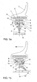
- a wiper blade is shown in which, unlike the wiper blade after Fig. 1 on the upper part 15 of the wiper strip an angle-parallel damping strip 16 is integrally formed, on which on the side facing the bend 9 a trough 17 is formed as a deformation space for this (16), as in Fig. 1a is shown.
- Fig. 2b shows that when striking the longitudinal edge 14 of the lower part 3 to the damping bar 16, this is deformed such that this (16) is pressed in the region of the trough 17 energy-consuming to the bend 9. As a result, the impact of the longitudinal edge 14 are attenuated on the damping bar 16 and attenuated the impact noise.
Landscapes
- Engineering & Computer Science (AREA)
- Physics & Mathematics (AREA)
- Fluid Mechanics (AREA)
- Quality & Reliability (AREA)
- Mechanical Engineering (AREA)
- Vibration Dampers (AREA)
- Springs (AREA)
- Body Structure For Vehicles (AREA)
Abstract
Description
- Die Erfindung betrifft ein Wischerblatt für einen Scheibenwischer an einem Fahrzeug, insbesondere ein haltebügelloses/ gelenkfreies Wischerblatt für die Frontscheibe des Fahrzeugs.
- Hältebügellose Wischerblätter bestehen im Wesentlichen aus einer aus einem gummielastischen Material gefertigten langgestreckten Wischleiste, die üblicherweise ein mit seitlichen Längsnuten versehenes Oberteil und ein mit diesem über zumindest einen Kippsteg verbundenes Unterteil mit einer Wischlippe aufweist, und einem mit der Wischleiste verbundenen und gegenüber der Scheibe konkav gekrümmter, federelastischen Tragelement. Dieses kann aus zwei parallelen Federschienen gebildet sein, die in den im Oberteil ausgebildeten Längsnuten angeordnet sind, oder auch aus einer bandartigen Federschiene, die in einem das Oberteil im wesentlichen U-förmig umschließenden Windleitprofil angeordnet ist, das wischleistenseitig offen ist und mit nach dem Oberteil zu abgewinkelten Schenkeln jeweils in eine Längsnut eingreift, wie es beispielsweise in der
DE 10 2005 009 205 A1 beschrieben ist. - Bei einem in der
DE 44 42 529 beschriebenen Wischerblatt ist das Tragelement ein steifes, im Wesentlichen U-förmiges Hohlprofil, insbesondere aus einem harten Kunststoff, in das die Wischleiste eingeschoben ist, wobei das Hohlprofil eine mit den Krümmungsradius der Scheibe identische Krümmung aufweist. Das Hohlprofil ist scheibenseit g offen und weist an seinen beiden Schenkeln zwei waagerecht nach innen abragende Stege auf, die aufeinander zu weisen und als Haltestege für die Wischleiste dienen. - Bei einem in der
WO 99/36300 - Beim Betreiben des jeweiligen Scheibenwischers wird die Wischlippe um den zumindest einen Kippsteg nach der jeweiligen Rückseite des über die Fahrzeugscheibe hin- und herbewegten Wischerblattes gekippt und am Bewegungs-Umkehrpunkt des Scheibenwischers nach der jeweils anderen, nun die Rückseite bildenden Seite umgelegt. Dieses Umlegen oder auch Umschnappen der Wischlippe ist mit einer störenden Geräuschentwicklung verbunden, die insbesondere durch ein Aufschlagen der jeweiligen Längskante des Unterteils auf die über dieser ausgebildeten Fläche des Oberteils im Bereich des Kippsteges hervorgerufen wird und einen hohen Geräuschpegel im Fahrzeug erzeugen kann.
- Es sind schon geräuschgedämpfte Wischleisten, insbesondere für haltebügellose Wischerblätter, bekannt geworden, beispielsweise durch die
DE 10 2005 009 205 A1 und dieDE 10 2005 021 146 A1 . Bei diesen sind in dem zwischen dem Oberteil, dem Unterteil und dem Kippsteg gebildeten Spalt Dämpfungsstege angeformt, die ein Anschlagen der jeweiligen Längskante des Unterteils auf die den Spalt mitbildende Fläche des Oberteils verhindern, zumindest jedoch erheblich dämpfen. Aus derDE 91 04 461 U1 ist es auch bekannt, zwischen dem Oberteil und dem Unterteil jeweils eine längserstreckte, das Querschnittsprofil der Wischleiste ergänzende und im spitzen Winkel zum Oberteil angeordnete Dämpfungsleiste vorzusehen, die verhindert, dass die Längskante des Unterteils auf die dieser zugewandte Fläche des Oberteils aufschlägt, sondern bewirkt, dass die Längskante zunächst gegen die Dämpfungsleiste schlägt, die elastisch nachgibt und in Richtung der Fläche des Oberteils energieverzehrend gebogen und bis zur Anlage "auf Block" an diese Fläche gedämpft geschlagen wird. - In Weiterentwicklung dazu ist schon vorgeschlagen worden, zwischen den jeweils im spitzen Winkel am Oberteil angeordneten Dämpfungsleisten, die ja mit dem Oberteil jeweils einen dreieckförmigen Deformationsraum für diese ausbilden, oberteilseitig eine Erweiterung dieses Deformationsraumes vorzusehen, indem das Oberteil zur Schaffung dieses erweiterten Deformationsraumes im Querschnitt auf der der Dämpfungsleiste zugewandten Seite konkav ausgebildet ist.
- Es ist Aufgabe der Erfindung, ein Wischerblatt für einen Scheibenwischer nach dem Oberbegriff des Anspruchs 1 so zu gestalten, dass bei diesem die Umlegegeräusche beseitigt, zumindest jedoch erheblich reduziert sind.
- Diese Aufgabe wird bei einem Wischerblatt nach dem Oberbegriff des Anspruchs 1 durch dessen kennzeichnenden Merkmale gelöst. Vorteilhafte Ausgestaltungen sind in den Unteransprüchen aufgeführt.
- Die Erfindung betrifft ein Wischerblatt, das in bekannter Weise eine Wischleiste mit einem Oberteil mit seitlich an diesem ausgebildeten Längsnuten und ein mit diesem über einen Kippsteg verbundenes Unterteil mit einer Wischlippe zur Anlage an einer Fahrzeugscheibe, ein elastisches Tragelement und ein dieses aufnehmendes formstabiles Hohlprofil aufweist. Letzteres ist zur Verbindung mit der Wischleiste wischlippenseitig mit zwei Schenkeln versehen, die nach der Wischleiste zu abgewinkelt sind und mit den Abwinklungen jeweils in eine Längsnut eingreifen und kann auf der der Wischlippe abgewar dten Seite zu einem formstabilen Windleitprofil (Spoiler) geformt sein. Die Erfindung besteht nur darin, dass zwischen der jeweiligen Abwinklung und einer die jeweilige Längsnut wischlippenseitig begrenzenden Dämpfungsleiste im Querschnitt ein Deformationsraum für diese ausgebildet ist. Dieser Deformationsraum ermöglicht beim Betreiben des Scheibenwischers, dass die jeweilige Dämpfungsleiste in diesen hinein deformierbar ist und demzufolge Aufprallenergie aufnehmen kann, so dass der Aufschlag der der Dämpfungsleiste benachbarten Längskante des Unterteils auf diese gedämpft wird. Die Flexibilität des Unterteils wird dabei nicht verringert, ebenso nicht dessen Fähigkeit, die von einem Wischerarm eingebrachte Anoresskraft auf die Wischlippe zu übertragen.
- Der Deformationsraum kann dabei an der jeweiligen Abwinklung und/ oder an der jeweiligen Dämpfungsleiste selbst ausgebildet sein. Auch bei letzterer Ausführung wird die Dämpfungsleiste deformiert und durch die Längskante des Unterteils zur Abwinklung zu deformiert, bevor sie an diese anschlägt. Der Deformationsraun wird auf einfache Weise durch eine längsnutseitige konkave Ausbildung der Abwinklung und/ oder der Dämpfungsleiste geschaffen. Zur konkaven Gestaltung der jeweiligen Querschrittsfläche kann längsnutseitig im Bereich der jeweiligen Außenkante ein längserstreckter Anlagesteg oder eine Anlagewulst für das andere Teil angeformt sein, durch den/ die ein in etwa dreleckiger Deformationsraum gebildet wird. Dieses Anlageelement kann auch aus einem Material mit einer wesentlich geringeren Shore-Härte als das Material der Wischleiste gebildet sein, vorzugsweise aus einem Material mit einer um die Hälfte geringeren Härte Shore A gegenüber dem Material der Wischleiste, insbesondere aus weichem EPDM, das beim Extrudieren der Wischleiste coextrudiert wird.
- Vorteilhaft ist es auch, wenn die Dämpfungsleiste nach dem Unterteil zu geneigt angeformt ist und dabei mit dem Oberteil einen Winkel von vorzugsweise 15 bis 25° einschließt. Ein Aufschlag der Längskante des Unterteils auf die Dämpfungsleiste wird dadurch gedämpft, dass diese in Richtung der Abwinklung aufprallenergieverzehrend deformiert wird und ein Anschlag "auf Block" verhindert ist, verbunden mit einer Geräuschdämpfung.
- Die Erfindung wird nachstehend anhand von Ausführungsbeispielen erläutert. In den zugehörigen Zeichnungen zeigen im Querschnitt:
- Fig. 1a:
- ein Wischerblatt im Querschnitt mit einen Deformationsraum für eine Dämpfungsleiste in einer ersten Ausführung in der Nichtbetriebsstellung,
- Fig. 1b:
- das Wischerblatt in einer Betriebsstellung,
- Fig. 2a:
- eine alternative Ausführung des Deformationsraumes in der Nichtgebcauchsstellung des Wischerblattes,
- Fig. 2b:
- die Deformation der Dämpfungsleiste bel dieser Ausführung in einer Betriebsstellung des Wischerblattes.
- Fig. 3a:
- eine weitere alternative Ausführung des Deformationsraumes in der Nichtgebrauchsstellung des Wischerblattes und
- Fig. 3b:
- die Deformation der Dämpfungsleiste bei dieser Ausführung in einer Betriebsstellung des Wischerblattes.
- Das in den
Fig. 1a und 1b gezeigte Wischerblatt weist eine Wischleiste aus Gummi mit.einem Oberteil 1 und einem über einen Kippsteg 2 mit diesem verbundenen Unterteil 3 mit einer Wischlippe 4 zur Anlage an einer Fahrzeugscheibe S, ein elastisch biegbares, zur Wischlippe zu konkaves Federstahl-Tragelement 5 und ein dieses (5) lose umschließendes formstabiles Hohlteil 6 auf, das auf der der Wischlippe 4 abgewandten Seite zu einem Windleitprofil 7 geformt ist. Am Hohlprofil 6 sind wischlippenseitig zwei Schenkeln 8 angeformt, die nach der Wischleiste zu um 90° abgewinkelt sind und mit diesen Abwinklungen 9 in am Oberteil 1 angeordnete Längsnuten 10 eingreifen und auf diese Weise die Wischleiste haltern. Die Längsnut 10 wird wischlippenseitig durch eine Dämpfungsleiste 11 begrenzt; die nach dem Unterteil 3 zu geneigt ist und dabei mit dem Oberteil 1 einen Winkel von im Wesentlichen 20° einschließt. An der jeweiligen Abwinklung 9 ist im Bereich deren Außenkante längsnutseitig ein Längserstreckter Anlagesteg 12 für die Dämpfungsleiste 11 zur Ausbildung einer gegenüber dieser (11) längserstreckten konkaven Mulde 13 als Deformationsraum angeformt. - Während des Betreibens des das Wischerblatt tragenden Scheibenwischers (nicht dargestellt) ist die Wischteiste nach der der Bewegungsrichtung (Pfeil) abgewandten Seite zu geneigt, was in
Fig. 1b gezeigt ist. Diese Neigung beträgt im Bereich der Wischlippe 4 etwa 45° und ist im wesentlichen durch den Kippsteg 2 ermöglicht. Bei einer Bewegungsumkehr des Scheibenwischers schlägt das Unterteil 3 nach der entgegengesetzten Richtung um und schlägt mit der jeweiligen (in der Fig. linken) Längskante 14 an die Unterseite der jeweiligen Dämpfungsleiste 11 an, die dabei in Richtung der Mulde 13 energieverzehrend deformiert wird und dadurch den Aufschlag der Längskante 14 dämpft. Zunächst dient der Anlagesteg 12 als Anschlag für die Dämpfungsleiste 11. Nach dem Anschlagen an diesen (12) wird die Dämpfungsleiste 11 durch die Längskante 14 in die Mulde 13 gedrückt und somit weiter deformiert. Durch die energieverzehrende Deformation der Dämpfungsleiste wird das Auftreten eines Schlaggeräusches weitgehend verhindert, zumindest jedoch stark gedämpft. - In den
Fig. 2a und b ist ein Wischerblatt gezeigt, bei dem im Unterschied zu dem Wischerblatt nachFig. 1 am Oberteil 15 der Wischleiste eine abwinklungsparallele Dämpfungsleiste 16 angeformt ist, an der auf der der Abwinklung 9 zugewandten Seite eine Mulde 17 als Deformationsraum für diese (16) ausgebildet ist, wie inFig. 1a dargestellt ist.Fig. 2b zeigt, dass beim Anschlagen der Längskante 14 des Unterteils 3 an die Dämpfungsleiste 16 diese derart deformiert wird, dass diese (16) im Bereich der Mulde 17 energieverzehrend an die Abwinklung 9 gedrückt wird. Dadurch werden der Aufschlag der Längskante 14 auf die Dämpfungsleiste 16 abgeschwächt und das Schlaggeräusch gedämpft. - Bei der Ausführung eines Wischerblattes nach den
Fig. 3a und 3b sind am Oberteil 18 Dämpfungsleisten 19 im Winkel von etwa 20° zu diesem angeformt. An diesen ist im Bereich deren jeweiliger Außenkante abwinklungsseitig eine Anlagewulst 20 aus EPDM mit einer Härte Shore-A von 60 anextrudiert, so dass eine Mulde 21 gebildet ist. Auch die Abwinklung 9 ist wischlippenseitig mit einer Mulde 22 versehen. Beide Mulden 21 und 22 bilden gemeinsam einen Deformationsraum 23 aus, in den die Dämpfungsleiste 19 beim Anschlagen der Anlagewulst 20 an die Außenkante der jeweiligen Abwinklung 9 energieverzehrend hineingedrückt wird. -
- 1
- Oberteil
- 2
- Kippsteg
- 3
- Unterteil
- 4
- Wischlippe
- 5
- Federstahlband
- 6
- Hohlteil
- 7
- Windleitprofil
- 8
- Schenkel
- 9
- Abwinklung
- 10
- Längsnut
- 11
- Dämpfungsleiste
- 12
- Anlagesteg
- 13
- Mulde
- 14
- Längskante
- 15
- Oberteil
- 16
- Dämpfungsleiste
- 17
- Mulde
- 18
- Oberteil
- 19
- Dämpfungsleiste
- 20
- Anlagewulst
- 21
- Mulde
- 22
- Mulde
- 23
- Deformationsraum
Claims (8)
- Wischerblatt für einen Scheibenwischer, mit einer Wisch eiste, einem federelastischen Tragelement und einem das Tragelement zumindest teilweise umschließenden formstabilen Hohlprofil, wobei die Wischleiste ein Oberteil mit Längsnuten, ein mit diesem zumindest über einen Kippsteg verbundenes Unterteil m t einer Wischlippe zur Anlage an einer Fahrzeugscheibe und wobei das Hohlprofil wischlippenseitig zwei Schenkel aufweist, die nach der Wischleiste zu abgewinkelt sind und mit den Abwinklungen jeweils in eine Längsnut eingreifen, dadurch gekennzeichnet, dass zwischen der jeweiligen Abwinklung (9) und einer die jeweilige Längsnut (10) wischlippenseitig begrenzenden Dämpfüngsleiste (11, 16, 19) ein Deformationsraum (13, 17, 21/ 22/ 23) für diese (11,16, 19) ausgebildet ist.
- Wischerblatt nach Anspruch 1, dadurch gekennzeichnet, dass der Deformationsraum (13, 17, 21/22) an der jeweiligen Abwinklung (9) oder/ und an der jeweiligen Dämpfungsleiste (11, 16, 19) ausgebildet ist.
- Wischerblatt nach Anspruch 1 oder 2, dadurch gekennzeichnet, dass die Abwinklung (9) oder/ und die Dämpfungsleiste (19) längsnutseitig zur Ausbildung des Deformationsraumes (13, 17, 21/22) im Querschnitt konkav ausgebildet ist.
- Wischerblatt nach Anspruch 1 oder 2, dadurch gekennzeichnet, dass die Abwinklung (9) oder die Dämpfungsleiste (11, 16, 19) längsnutseitig im Bereich ihrer Außenkante einen längserstreckten Anlagesteg (12) oder eine Anlagewulst (20) für das jeweils andere Teil aufweist, die jeweils eine Mulde (13, 21) als Deformationsraum ausbildet.
- Wischerblatt nach einem oder mehreren der vorhergehenden Ansprüche, dadurch gekennzeichnet, dass die Dämpfungsleiste (11, 19) nach dem Unterteil (3) zu geneigt ist und dabei mit dem Oberteil (1) einen Winkel von vorzugsweise 15 bis 25° einschließt.
- Wischerblatt nach Anspruch 4, dadurch gekennzeichnet, dass der Anlagesteg (12) oder die Anlagewulst (20) aus einem Material mit einer wesentlich geringeren Shore-A-Härte als das Material der Wischleiste gebildet ist, insbesondere aus einem Material mit einer um die Hälfte geringeren Härte Shore A.
- Wischerblatt nach Anspruch 6, dadurch gekennzeichnet dass das Material des Anlagesteges (12) oder der Anlagewulst (20) weiches EPDM ist, das beim Extrudieren der Wischleiste coextrudiert wird.
- Wischerblatt nach Anspruch 1, dadurch gekennzeichnet dass das Hohlprofil (6) auf der der Wischlippe abgewandten Seite zu einem Windleitprofil (7) geformt ist.
Applications Claiming Priority (1)
| Application Number | Priority Date | Filing Date | Title |
|---|---|---|---|
| DE102007011732A DE102007011732A1 (de) | 2007-03-10 | 2007-03-10 | Wischerblatt für einen Scheibenwischer |
Publications (3)
| Publication Number | Publication Date |
|---|---|
| EP1970268A2 true EP1970268A2 (de) | 2008-09-17 |
| EP1970268A3 EP1970268A3 (de) | 2009-12-02 |
| EP1970268B1 EP1970268B1 (de) | 2012-02-15 |
Family
ID=39406139
Family Applications (1)
| Application Number | Title | Priority Date | Filing Date |
|---|---|---|---|
| EP08004148A Not-in-force EP1970268B1 (de) | 2007-03-10 | 2008-03-06 | Wischerblatt für einen Scheibenwischer |
Country Status (3)
| Country | Link |
|---|---|
| EP (1) | EP1970268B1 (de) |
| AT (1) | ATE545553T1 (de) |
| DE (1) | DE102007011732A1 (de) |
Cited By (1)
| Publication number | Priority date | Publication date | Assignee | Title |
|---|---|---|---|---|
| WO2020216560A1 (de) * | 2019-04-25 | 2020-10-29 | Robert Bosch Gmbh | Wischleisteneinheit |
Citations (5)
| Publication number | Priority date | Publication date | Assignee | Title |
|---|---|---|---|---|
| DE9104461U1 (de) | 1991-04-12 | 1992-08-06 | Robert Bosch Gmbh, 7000 Stuttgart | Wischblatt zum pendelnden Überstreichen von Scheiben an Kraftfahrzeugen |
| DE4442529A1 (de) | 1994-11-30 | 1996-06-05 | Daimler Benz Ag | Wischblatt für einen Scheibenwischer zum Wischen einer Scheibe mit konstantem Krümmungsradius |
| WO1999036300A1 (de) | 1998-01-14 | 1999-07-22 | Robert Bosch Gmbh | Wischblatt zum reinigen von scheiben von kraftfahrzeugen |
| DE102005009205A1 (de) | 2004-03-16 | 2005-10-06 | Volkswagen Ag | Haltebügelloses Wischerblatt für einen Scheibenwischer |
| DE102005021146A1 (de) | 2005-05-06 | 2006-11-09 | Volkswagen Ag | Haltebügelloses Wischerblatt für einen Scheibenwischer |
Family Cites Families (5)
| Publication number | Priority date | Publication date | Assignee | Title |
|---|---|---|---|---|
| DE3904152A1 (de) * | 1989-02-11 | 1990-08-16 | Swf Auto Electric Gmbh | Gummielastisches teil und verfahren zu seiner herstellung |
| DE19609578A1 (de) * | 1996-03-12 | 1997-09-18 | Bosch Gmbh Robert | Wischblatt für Scheiben von Kraftfahrzeugen |
| DE19745006A1 (de) * | 1997-10-11 | 1999-04-22 | Bosch Gmbh Robert | Wischanlage |
| DE10022724A1 (de) * | 2000-05-10 | 2001-11-22 | Bosch Gmbh Robert | Wischleiste für Scheibenwischer |
| FR2868747B1 (fr) * | 2004-04-07 | 2008-06-20 | Valeo Systemes Dessuyage | Balai d'essuie-glace de type flat-blade comportant un deflecteur aerodynamique |
-
2007
- 2007-03-10 DE DE102007011732A patent/DE102007011732A1/de not_active Withdrawn
-
2008
- 2008-03-06 EP EP08004148A patent/EP1970268B1/de not_active Not-in-force
- 2008-03-06 AT AT08004148T patent/ATE545553T1/de active
Patent Citations (5)
| Publication number | Priority date | Publication date | Assignee | Title |
|---|---|---|---|---|
| DE9104461U1 (de) | 1991-04-12 | 1992-08-06 | Robert Bosch Gmbh, 7000 Stuttgart | Wischblatt zum pendelnden Überstreichen von Scheiben an Kraftfahrzeugen |
| DE4442529A1 (de) | 1994-11-30 | 1996-06-05 | Daimler Benz Ag | Wischblatt für einen Scheibenwischer zum Wischen einer Scheibe mit konstantem Krümmungsradius |
| WO1999036300A1 (de) | 1998-01-14 | 1999-07-22 | Robert Bosch Gmbh | Wischblatt zum reinigen von scheiben von kraftfahrzeugen |
| DE102005009205A1 (de) | 2004-03-16 | 2005-10-06 | Volkswagen Ag | Haltebügelloses Wischerblatt für einen Scheibenwischer |
| DE102005021146A1 (de) | 2005-05-06 | 2006-11-09 | Volkswagen Ag | Haltebügelloses Wischerblatt für einen Scheibenwischer |
Cited By (2)
| Publication number | Priority date | Publication date | Assignee | Title |
|---|---|---|---|---|
| WO2020216560A1 (de) * | 2019-04-25 | 2020-10-29 | Robert Bosch Gmbh | Wischleisteneinheit |
| CN113677571A (zh) * | 2019-04-25 | 2021-11-19 | 罗伯特·博世有限公司 | 刮水条单元 |
Also Published As
| Publication number | Publication date |
|---|---|
| EP1970268A3 (de) | 2009-12-02 |
| DE102007011732A1 (de) | 2008-09-11 |
| ATE545553T1 (de) | 2012-03-15 |
| EP1970268B1 (de) | 2012-02-15 |
Similar Documents
| Publication | Publication Date | Title |
|---|---|---|
| EP1802497B1 (de) | Wischblatt | |
| EP2102042B1 (de) | Scheibenwischergummi | |
| EP1385722A1 (de) | Wischblatt zum reinigen von scheiben, insbesondere von kraftfahrzeugen | |
| EP1289806A1 (de) | Wischblatt zum reinigen von scheiben insbesondere von kraftfahrzeugen | |
| WO2006048355A1 (de) | Wischblatt | |
| WO2004076251A1 (de) | Wischblatt zum reinigen von scheiben, insbesondere von kraftfahrzeugen | |
| DE102005009205B4 (de) | Haltebügelloses Wischerblatt für einen Scheibenwischer | |
| EP3710317B1 (de) | Wischblatt | |
| EP1970268B1 (de) | Wischerblatt für einen Scheibenwischer | |
| EP1948489B1 (de) | Wischgummi für das wischerblatt eines scheibenwischers | |
| DE102005021146B4 (de) | Haltebügelloses Wischerblatt für einen Scheibenwischer | |
| EP1767416A2 (de) | Gummielastische Wischleiste für das Wischerblatt eines Scheibenwischers | |
| DE1074429B (de) | Pendelscheibenwischer | |
| EP2079616B1 (de) | Wischleiste und wischblatt mit einer solchen wischleiste | |
| DE102008017250B4 (de) | Geräuschgedämpftes Wischerblatt für einen Scheibenwischer an einem Fahrzeug | |
| DE2638010A1 (de) | Wischblatt | |
| EP1837258A2 (de) | Wischblatt | |
| EP2276655B1 (de) | Geräuschgedämpftes wischerblatt eines scheibenwischers an einem fahrzeug | |
| DE102008040410A1 (de) | Wischleiste für ein Wischblatt | |
| WO2009068266A1 (de) | Wischelement und wischerblatt für ein fahrzeug | |
| EP1206378B1 (de) | Wischblatt zum reinigen einer insbesonderen gewölbten scheibe an einem fahrzeug | |
| DE102007033594B4 (de) | Wischerblatt für einen Scheibenwischer | |
| DE102007038576A1 (de) | Geräuschgedämpftes Wischerblatt für einen Scheibenwischer an einem Fahrzeug | |
| DE102004058511A1 (de) | Scheibenwischer für die Frontscheibe an einem Fahrzeug | |
| DE102011077516A1 (de) | Wischblatt zum Reinigen von Scheiben insbesondere von Kraftfahrzeugen |
Legal Events
| Date | Code | Title | Description |
|---|---|---|---|
| PUAI | Public reference made under article 153(3) epc to a published international application that has entered the european phase |
Free format text: ORIGINAL CODE: 0009012 |
|
| AK | Designated contracting states |
Kind code of ref document: A2 Designated state(s): AT BE BG CH CY CZ DE DK EE ES FI FR GB GR HR HU IE IS IT LI LT LU LV MC MT NL NO PL PT RO SE SI SK TR |
|
| AX | Request for extension of the european patent |
Extension state: AL BA MK RS |
|
| PUAL | Search report despatched |
Free format text: ORIGINAL CODE: 0009013 |
|
| AK | Designated contracting states |
Kind code of ref document: A3 Designated state(s): AT BE BG CH CY CZ DE DK EE ES FI FR GB GR HR HU IE IS IT LI LT LU LV MC MT NL NO PL PT RO SE SI SK TR |
|
| AX | Request for extension of the european patent |
Extension state: AL BA MK RS |
|
| 17P | Request for examination filed |
Effective date: 20100602 |
|
| 17Q | First examination report despatched |
Effective date: 20100713 |
|
| AKX | Designation fees paid |
Designated state(s): AT BE BG CH CY CZ DE DK EE ES FI FR GB GR HR HU IE IS IT LI LT LU LV MC MT NL NO PL PT RO SE SI SK TR |
|
| GRAP | Despatch of communication of intention to grant a patent |
Free format text: ORIGINAL CODE: EPIDOSNIGR1 |
|
| RIC1 | Information provided on ipc code assigned before grant |
Ipc: B60S 1/38 20060101AFI20110801BHEP |
|
| GRAS | Grant fee paid |
Free format text: ORIGINAL CODE: EPIDOSNIGR3 |
|
| GRAA | (expected) grant |
Free format text: ORIGINAL CODE: 0009210 |
|
| AK | Designated contracting states |
Kind code of ref document: B1 Designated state(s): AT BE BG CH CY CZ DE DK EE ES FI FR GB GR HR HU IE IS IT LI LT LU LV MC MT NL NO PL PT RO SE SI SK TR |
|
| REG | Reference to a national code |
Ref country code: GB Ref legal event code: FG4D Free format text: NOT ENGLISH Ref country code: CH Ref legal event code: EP |
|
| REG | Reference to a national code |
Ref country code: IE Ref legal event code: FG4D Free format text: LANGUAGE OF EP DOCUMENT: GERMAN |
|
| REG | Reference to a national code |
Ref country code: AT Ref legal event code: REF Ref document number: 545553 Country of ref document: AT Kind code of ref document: T Effective date: 20120315 |
|
| REG | Reference to a national code |
Ref country code: DE Ref legal event code: R096 Ref document number: 502008006389 Country of ref document: DE Effective date: 20120412 |
|
| REG | Reference to a national code |
Ref country code: NL Ref legal event code: VDEP Effective date: 20120215 |
|
| RAP2 | Party data changed (patent owner data changed or rights of a patent transferred) |
Owner name: VOLKSWAGEN AKTIENGESELLSCHAFT |
|
| LTIE | Lt: invalidation of european patent or patent extension |
Effective date: 20120215 |
|
| PG25 | Lapsed in a contracting state [announced via postgrant information from national office to epo] |
Ref country code: NL Free format text: LAPSE BECAUSE OF FAILURE TO SUBMIT A TRANSLATION OF THE DESCRIPTION OR TO PAY THE FEE WITHIN THE PRESCRIBED TIME-LIMIT Effective date: 20120215 Ref country code: NO Free format text: LAPSE BECAUSE OF FAILURE TO SUBMIT A TRANSLATION OF THE DESCRIPTION OR TO PAY THE FEE WITHIN THE PRESCRIBED TIME-LIMIT Effective date: 20120515 Ref country code: HR Free format text: LAPSE BECAUSE OF FAILURE TO SUBMIT A TRANSLATION OF THE DESCRIPTION OR TO PAY THE FEE WITHIN THE PRESCRIBED TIME-LIMIT Effective date: 20120215 Ref country code: IS Free format text: LAPSE BECAUSE OF FAILURE TO SUBMIT A TRANSLATION OF THE DESCRIPTION OR TO PAY THE FEE WITHIN THE PRESCRIBED TIME-LIMIT Effective date: 20120615 Ref country code: LT Free format text: LAPSE BECAUSE OF FAILURE TO SUBMIT A TRANSLATION OF THE DESCRIPTION OR TO PAY THE FEE WITHIN THE PRESCRIBED TIME-LIMIT Effective date: 20120215 |
|
| PG25 | Lapsed in a contracting state [announced via postgrant information from national office to epo] |
Ref country code: PT Free format text: LAPSE BECAUSE OF FAILURE TO SUBMIT A TRANSLATION OF THE DESCRIPTION OR TO PAY THE FEE WITHIN THE PRESCRIBED TIME-LIMIT Effective date: 20120615 Ref country code: FI Free format text: LAPSE BECAUSE OF FAILURE TO SUBMIT A TRANSLATION OF THE DESCRIPTION OR TO PAY THE FEE WITHIN THE PRESCRIBED TIME-LIMIT Effective date: 20120215 Ref country code: LV Free format text: LAPSE BECAUSE OF FAILURE TO SUBMIT A TRANSLATION OF THE DESCRIPTION OR TO PAY THE FEE WITHIN THE PRESCRIBED TIME-LIMIT Effective date: 20120215 Ref country code: PL Free format text: LAPSE BECAUSE OF FAILURE TO SUBMIT A TRANSLATION OF THE DESCRIPTION OR TO PAY THE FEE WITHIN THE PRESCRIBED TIME-LIMIT Effective date: 20120215 Ref country code: GR Free format text: LAPSE BECAUSE OF FAILURE TO SUBMIT A TRANSLATION OF THE DESCRIPTION OR TO PAY THE FEE WITHIN THE PRESCRIBED TIME-LIMIT Effective date: 20120516 |
|
| REG | Reference to a national code |
Ref country code: IE Ref legal event code: FD4D |
|
| PG25 | Lapsed in a contracting state [announced via postgrant information from national office to epo] |
Ref country code: CY Free format text: LAPSE BECAUSE OF FAILURE TO SUBMIT A TRANSLATION OF THE DESCRIPTION OR TO PAY THE FEE WITHIN THE PRESCRIBED TIME-LIMIT Effective date: 20120215 |
|
| BERE | Be: lapsed |
Owner name: VOLKSWAGEN Effective date: 20120331 |
|
| PG25 | Lapsed in a contracting state [announced via postgrant information from national office to epo] |
Ref country code: DK Free format text: LAPSE BECAUSE OF FAILURE TO SUBMIT A TRANSLATION OF THE DESCRIPTION OR TO PAY THE FEE WITHIN THE PRESCRIBED TIME-LIMIT Effective date: 20120215 Ref country code: CZ Free format text: LAPSE BECAUSE OF FAILURE TO SUBMIT A TRANSLATION OF THE DESCRIPTION OR TO PAY THE FEE WITHIN THE PRESCRIBED TIME-LIMIT Effective date: 20120215 Ref country code: IE Free format text: LAPSE BECAUSE OF FAILURE TO SUBMIT A TRANSLATION OF THE DESCRIPTION OR TO PAY THE FEE WITHIN THE PRESCRIBED TIME-LIMIT Effective date: 20120215 Ref country code: EE Free format text: LAPSE BECAUSE OF FAILURE TO SUBMIT A TRANSLATION OF THE DESCRIPTION OR TO PAY THE FEE WITHIN THE PRESCRIBED TIME-LIMIT Effective date: 20120215 Ref country code: RO Free format text: LAPSE BECAUSE OF FAILURE TO SUBMIT A TRANSLATION OF THE DESCRIPTION OR TO PAY THE FEE WITHIN THE PRESCRIBED TIME-LIMIT Effective date: 20120215 Ref country code: MC Free format text: LAPSE BECAUSE OF NON-PAYMENT OF DUE FEES Effective date: 20120331 Ref country code: SE Free format text: LAPSE BECAUSE OF FAILURE TO SUBMIT A TRANSLATION OF THE DESCRIPTION OR TO PAY THE FEE WITHIN THE PRESCRIBED TIME-LIMIT Effective date: 20120215 Ref country code: SI Free format text: LAPSE BECAUSE OF FAILURE TO SUBMIT A TRANSLATION OF THE DESCRIPTION OR TO PAY THE FEE WITHIN THE PRESCRIBED TIME-LIMIT Effective date: 20120215 |
|
| REG | Reference to a national code |
Ref country code: CH Ref legal event code: PL |
|
| PG25 | Lapsed in a contracting state [announced via postgrant information from national office to epo] |
Ref country code: SK Free format text: LAPSE BECAUSE OF FAILURE TO SUBMIT A TRANSLATION OF THE DESCRIPTION OR TO PAY THE FEE WITHIN THE PRESCRIBED TIME-LIMIT Effective date: 20120215 Ref country code: IT Free format text: LAPSE BECAUSE OF FAILURE TO SUBMIT A TRANSLATION OF THE DESCRIPTION OR TO PAY THE FEE WITHIN THE PRESCRIBED TIME-LIMIT Effective date: 20120215 |
|
| PLBE | No opposition filed within time limit |
Free format text: ORIGINAL CODE: 0009261 |
|
| STAA | Information on the status of an ep patent application or granted ep patent |
Free format text: STATUS: NO OPPOSITION FILED WITHIN TIME LIMIT |
|
| 26N | No opposition filed |
Effective date: 20121116 |
|
| GBPC | Gb: european patent ceased through non-payment of renewal fee |
Effective date: 20120515 |
|
| PG25 | Lapsed in a contracting state [announced via postgrant information from national office to epo] |
Ref country code: CH Free format text: LAPSE BECAUSE OF NON-PAYMENT OF DUE FEES Effective date: 20120331 Ref country code: BE Free format text: LAPSE BECAUSE OF NON-PAYMENT OF DUE FEES Effective date: 20120331 Ref country code: LI Free format text: LAPSE BECAUSE OF NON-PAYMENT OF DUE FEES Effective date: 20120331 |
|
| REG | Reference to a national code |
Ref country code: DE Ref legal event code: R097 Ref document number: 502008006389 Country of ref document: DE Effective date: 20121116 |
|
| PG25 | Lapsed in a contracting state [announced via postgrant information from national office to epo] |
Ref country code: ES Free format text: LAPSE BECAUSE OF FAILURE TO SUBMIT A TRANSLATION OF THE DESCRIPTION OR TO PAY THE FEE WITHIN THE PRESCRIBED TIME-LIMIT Effective date: 20120526 Ref country code: GB Free format text: LAPSE BECAUSE OF NON-PAYMENT OF DUE FEES Effective date: 20120515 |
|
| PG25 | Lapsed in a contracting state [announced via postgrant information from national office to epo] |
Ref country code: MT Free format text: LAPSE BECAUSE OF FAILURE TO SUBMIT A TRANSLATION OF THE DESCRIPTION OR TO PAY THE FEE WITHIN THE PRESCRIBED TIME-LIMIT Effective date: 20120215 Ref country code: BG Free format text: LAPSE BECAUSE OF FAILURE TO SUBMIT A TRANSLATION OF THE DESCRIPTION OR TO PAY THE FEE WITHIN THE PRESCRIBED TIME-LIMIT Effective date: 20120515 |
|
| PG25 | Lapsed in a contracting state [announced via postgrant information from national office to epo] |
Ref country code: TR Free format text: LAPSE BECAUSE OF FAILURE TO SUBMIT A TRANSLATION OF THE DESCRIPTION OR TO PAY THE FEE WITHIN THE PRESCRIBED TIME-LIMIT Effective date: 20120215 |
|
| REG | Reference to a national code |
Ref country code: AT Ref legal event code: MM01 Ref document number: 545553 Country of ref document: AT Kind code of ref document: T Effective date: 20130306 |
|
| PG25 | Lapsed in a contracting state [announced via postgrant information from national office to epo] |
Ref country code: LU Free format text: LAPSE BECAUSE OF NON-PAYMENT OF DUE FEES Effective date: 20120306 |
|
| PG25 | Lapsed in a contracting state [announced via postgrant information from national office to epo] |
Ref country code: HU Free format text: LAPSE BECAUSE OF FAILURE TO SUBMIT A TRANSLATION OF THE DESCRIPTION OR TO PAY THE FEE WITHIN THE PRESCRIBED TIME-LIMIT Effective date: 20080306 |
|
| PG25 | Lapsed in a contracting state [announced via postgrant information from national office to epo] |
Ref country code: AT Free format text: LAPSE BECAUSE OF NON-PAYMENT OF DUE FEES Effective date: 20130306 |
|
| REG | Reference to a national code |
Ref country code: FR Ref legal event code: PLFP Year of fee payment: 9 |
|
| REG | Reference to a national code |
Ref country code: FR Ref legal event code: PLFP Year of fee payment: 10 |
|
| REG | Reference to a national code |
Ref country code: FR Ref legal event code: PLFP Year of fee payment: 11 |
|
| REG | Reference to a national code |
Ref country code: DE Ref legal event code: R084 Ref document number: 502008006389 Country of ref document: DE |
|
| P01 | Opt-out of the competence of the unified patent court (upc) registered |
Effective date: 20230523 |
|
| PGFP | Annual fee paid to national office [announced via postgrant information from national office to epo] |
Ref country code: DE Payment date: 20240331 Year of fee payment: 17 |
|
| PGFP | Annual fee paid to national office [announced via postgrant information from national office to epo] |
Ref country code: FR Payment date: 20240327 Year of fee payment: 17 |
|
| REG | Reference to a national code |
Ref country code: DE Ref legal event code: R119 Ref document number: 502008006389 Country of ref document: DE |
|
| PG25 | Lapsed in a contracting state [announced via postgrant information from national office to epo] |
Ref country code: DE Free format text: LAPSE BECAUSE OF NON-PAYMENT OF DUE FEES Effective date: 20251001 |
|
| PG25 | Lapsed in a contracting state [announced via postgrant information from national office to epo] |
Ref country code: FR Free format text: LAPSE BECAUSE OF NON-PAYMENT OF DUE FEES Effective date: 20250331 |