EP1970285A2 - Kinderwagen mit einem Kindersitz - Google Patents
Kinderwagen mit einem Kindersitz Download PDFInfo
- Publication number
- EP1970285A2 EP1970285A2 EP08102687A EP08102687A EP1970285A2 EP 1970285 A2 EP1970285 A2 EP 1970285A2 EP 08102687 A EP08102687 A EP 08102687A EP 08102687 A EP08102687 A EP 08102687A EP 1970285 A2 EP1970285 A2 EP 1970285A2
- Authority
- EP
- European Patent Office
- Prior art keywords
- bracket
- child seat
- coupling
- undercarriage
- stroller
- Prior art date
- Legal status (The legal status is an assumption and is not a legal conclusion. Google has not performed a legal analysis and makes no representation as to the accuracy of the status listed.)
- Granted
Links
- 230000008878 coupling Effects 0.000 description 60
- 238000010168 coupling process Methods 0.000 description 60
- 238000005859 coupling reaction Methods 0.000 description 60
- 239000002184 metal Substances 0.000 description 12
- 230000003213 activating effect Effects 0.000 description 8
- 238000010276 construction Methods 0.000 description 1
Images



Classifications
-
- B—PERFORMING OPERATIONS; TRANSPORTING
- B62—LAND VEHICLES FOR TRAVELLING OTHERWISE THAN ON RAILS
- B62B—HAND-PROPELLED VEHICLES, e.g. HAND CARTS OR PERAMBULATORS; SLEDGES
- B62B7/00—Carriages for children; Perambulators, e.g. dolls' perambulators
- B62B7/04—Carriages for children; Perambulators, e.g. dolls' perambulators having more than one wheel axis; Steering devices therefor
- B62B7/14—Carriages for children; Perambulators, e.g. dolls' perambulators having more than one wheel axis; Steering devices therefor with detachable or rotatably-mounted body
- B62B7/142—Means for securing the body to the frame
-
- B—PERFORMING OPERATIONS; TRANSPORTING
- B62—LAND VEHICLES FOR TRAVELLING OTHERWISE THAN ON RAILS
- B62B—HAND-PROPELLED VEHICLES, e.g. HAND CARTS OR PERAMBULATORS; SLEDGES
- B62B7/00—Carriages for children; Perambulators, e.g. dolls' perambulators
- B62B7/04—Carriages for children; Perambulators, e.g. dolls' perambulators having more than one wheel axis; Steering devices therefor
- B62B7/14—Carriages for children; Perambulators, e.g. dolls' perambulators having more than one wheel axis; Steering devices therefor with detachable or rotatably-mounted body
- B62B7/145—Carriages for children; Perambulators, e.g. dolls' perambulators having more than one wheel axis; Steering devices therefor with detachable or rotatably-mounted body the body being a rigid seat, e.g. a shell
-
- B—PERFORMING OPERATIONS; TRANSPORTING
- B62—LAND VEHICLES FOR TRAVELLING OTHERWISE THAN ON RAILS
- B62B—HAND-PROPELLED VEHICLES, e.g. HAND CARTS OR PERAMBULATORS; SLEDGES
- B62B7/00—Carriages for children; Perambulators, e.g. dolls' perambulators
- B62B7/04—Carriages for children; Perambulators, e.g. dolls' perambulators having more than one wheel axis; Steering devices therefor
- B62B7/14—Carriages for children; Perambulators, e.g. dolls' perambulators having more than one wheel axis; Steering devices therefor with detachable or rotatably-mounted body
- B62B7/147—Carriages for children; Perambulators, e.g. dolls' perambulators having more than one wheel axis; Steering devices therefor with detachable or rotatably-mounted body rotatable as a whole to transform from seating to lying
Definitions
- the invention concerns a stroller with a child seat according to the preamble of claim 1.
- a stroller is known, for instance from EP 0827890 .
- the disadvantage of the known stroller is that the child seat can tilt to all inclination angles independent of the type of child seat that is mounted on the undercarriage.
- the bracket is suitable for tilting a child seat suitable for older children for instance over 60 degrees. Tilting a baby seat over this angle might lead to dangerous situations which is undesirable.
- the stroller is according to claim 1.
- the child seats that are coupled on the bracket can activate the sensor pin. If a child seat moves the sensor pin to the second position the tilting angle of the bracket is can be positioned at one angle, for instance if the child seat is a carry cot, or at two angles if the child seat is a baby seat. If the child seat is for older children the child seat does not move the sensor pin to the second position and the child seat can be tilted to all available angles.
- the stroller is according to claim 2. In this way it is ensured that a child seat for which the bracket has to be in a predetermined inclination angle can only be coupled to the bracket if the bracket is in that predetermined inclination angle.
- the stroller is according to claim 3.
- the bracket is supported in a stable way whereby the undercarriage can be folded without having to adjust the bracket.
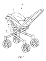
- Figure 1 shows a stroller 1 with an undercarriage 8 and a child seat 2 connected thereto.
- the child seat 2 has a support 3 that is coupled to the undercarriage 8 by a coupling bracket 4.
- the coupling bracket 4 is coupled by a first support bar 6 and a second support bar 7 to the undercarriage 8.
- the coupling bracket 4 has a release button 5 which is described more extensively later.
- Figures 2 , 4 , 5 and 6 show a first embodiment of the coupling bracket 4 and its connection to the support 3 of the child seat 2.
- the coupling bracket 4 is U - shaped and the ends of the legs of the U rest against the support 3.
- the distance between the legs where they are connected to the support 3 is at least 80 mm.
- the support 3 has two cavities 12 on each side of the child seat 2, which cavities 12 are shaped such that they narrowly enclose cams 13 which are on the ends of the legs of the coupling brackets 4.
- a metal plate 15 is fastened with screws 14 to the underside of the support 3.
- the ends of the metal plate 15 extend in the cavities 12.
- a first hook 11 extends upwards between the two cams 13 and can hook around the first end of the metal plate 15 and at the end of the other leg of the coupling bracket 4 a second hook 17 extends upwards between the two cams 13 and can hook around the other end of the metal plate 15.
- the first hook 11 can rotate around a swivel pin 21 and is activated by a activating bar 23 which connects to the first hook 11 with a coupling pin 22.
- the second hook 17 can rotate around a swivel pin 19 and is coupled to the activating bar 23 with a coupling pin 18.
- the coupling pins 18 and 22 and the swivel pins 19 and 21 are located such that with movement of the activating bar 23 the first hook 11 and the second hook 17 counter rotate.
- the activating bar 23 is pushed by a spring 20 in a direction so that the activating bar 23 pushes the upper ends of the first hook 11 and the second hook 17 towards the metal plate 15.
- the support 3 For mounting the child seat 2 on the coupling bracket 4 the support 3 is positioned with its cavities 12 above the cams 13 and moved towards the coupling bracket 4.
- the cams 13 position the support 3 accurately relative to the coupling bracket 4.
- the metal plate 15 touches the top of the first hook 11 and the top of the second hook 17 and due to the shapes of the hooks 11 and 17 pushes the hooks outwards against the force of the spring 20 until they snap around the metal plate 15 and hold the brace 10 of the support 3 against the crest 9 of the coupling bracket 4.
- a hand is placed around each grip 16 and the activating bar 23 is pushed against the force of the spring 20 and the first hook 11 and the second hook 17 move outwards and the child seat 2 can be lifted off.
- the coupling bracket 4 is provided with a first rail 30 along which a first arcuate slide 27 can move along an arcuate path.
- the radius of this arcuate path is at least half the distance between the cavities 12 and preferably more than 50 mm so that when swivelling the arcuate slide 27 has to travel a considerable distance and play between the arcuate slide 27 and the rail 30 does not lead to undesired movement of the child seat 2.
- the first support bar 6 is connected to the first arcuate slide 27 and can rotate relative the coupling bracket 4 around the center of the arcuate path and thereby moves in an opening 31 of the outer circumference 4 of the coupling bracket 4.
- the first arcuate slide 27 has a plate 24 with holes 35 in which a catch 25 can be pushed so that the position of the first arcuate slide 27 is locked.
- the catch 25 has a pointed end that is pushed by a spring 37 in one of the holes 35 of the plate 24.
- the catch 25 has a retraction pin 34 which slides along a sloped surface 33 of the release button 5.
- the sloped surface 33 moves along the retraction pin 34 and pushes the catch 25 against the force of the spring 37 out of the hole 35 so that the first arcuate slide 27 can be moved along the rail 30 and the child seat 2 can be swivelled around a rotation axis formed by the centers of the arcuate paths of both coupling brackets 4.
- a second arcuate slide 29 is in the first arcuate slide 27 and can move along a second rail 28.
- the second support bar 7 is connected to the second arcuate slide 29 and extends through an opening in the first arcuate slide 27 and the opening 31 in the coupling bracket 4. This makes a relative movement of the first support bar 6 and the second support bar 7 possible, which is for instance necessary when folding the undercarriage 8.
- first hook 11 and the second hook 17 couple to the metal plate 15 which is part of the support 3.
- metal plate 15 is replaced by pins around which the hooks 11 and 17 can couple in a similar way.
- the embodiment shows an arcuate slide 27 moving inside a C - shaped housing with inside the housing rail 30. It is clear that other rail/slide constructions are possible, for instance whereby the arcuate slide surrounds a tube bent in a radius.
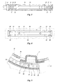
- Figure 7a shows a second embodiment of the coupling bracket 4 whereby the coupling bracket 4 is connected with only the first support bar 6 to the undercarriage.
- the first support bar 6 is connected to the end of the first arcuate slide 27, in other embodiments it is possible that the first support bar 6 is connected to the middle of the first arcuate slide 27 or any other location of the slide 27.
- Figure 7a shows the situation whereby the support 3 with the child seat 2 is severely inclined
- figure 7b shows the situation whereby the support 3 with the child seat 2 is more or less horizontal.
- Figure 8a shows a further embodiment of the coupling bracket 4 which is similar to the coupling bracket 4 described in the figures 2 - 6 , whereby the coupling bracket 4 is connected by the first support bar 6 and the second support bar 7 to the undercarriage 8.
- figure 8a shows the situation whereby the support 3 with the child seat is more or less horizontal.
- Figure 9a shows a further embodiment of the coupling bracket 4 whereby the coupling bracket 4 is connected by the first support bar 6 and the second support bar 7 to the undercarriage 8.
- the first support bar 6 is fastened to one end of an arcuate slide 39 and the second support bar 7 is connected to a pivot 38 at the other end of the arcuate slide 39.
- the arcuate slide 39 is firmly supported by the first support bar 6 and the second support bar 7 which can rotate relative one another in an easy way.
- Figure 10a shows a further embodiment of the bracket 4 whereby a child seat is supported by a first coupling surface 43 and a second coupling surface 41.
- the first coupling surface 43 and the second coupling surface 41 form a flat plane.
- the first hook 11 extends above the first coupling surface 41 and the second hook 17 extends above the first coupling surface 43.
- the movements of the first hook 11 and the second hook 17 are coupled by the connecting bar 23 which is moved by activating a button 42.
- the bracket 4 has a C-shaped body in which the first arcuate slide 27 can move as described earlier.
- the arcuate slide 27 is provided with notches 46 in which a pin 45 can be moved by a spring 44 so that the arcuate slide 27 is locked in a position. By moving the release button 5 the arcuate slide 27 can slide in the bracket 4.
- the movement of the arcuate slide 27 can be blocked by a locking plate 48 as is shown in figure 10b .
- This locking plate 48 can slide in a guide slot 47 inside the bracket 4.
- the locking plate 48 has an opening through which a pin 40 extends so that the movement of the locking plate 48 and the pin 40 are coupled.
- the pin 40 extends above the second coupling surface 41 and can be pushed downwards against a force of a spring 50. This pushing downwards is desirable when the child seat 2 that is placed on the bracket 4 is for instance a carry cot and it is desirable to prevent tilting.
- the spring loaded metal pin 40 extends above the second coupling surface 41 and is pushed downwards by the carry cot.
- FIGS 11 - 14 show a further embodiment of the coupling bracket 4 in various positions of use.
- the coupling bracket 4 has a closed housing with cams 13 on top.
- a hook 52 is provided between the cams 13 for coupling and/or locking a child seat on the coupling bracket 4.
- In the housing is a tilt position disk 54 (see figures 12 - 14 ) that is connected to the first support bar 6.
- a ring 51 can rotate in and/or is supported by the tilt position disk 54, the second support bar 7 is connected to the ring 51.
- the tilt position disk 54 can rotate with its inner wall 66 around a circular guide 65 and has five fixed rotative positions in the coupling bracket 4 whereby for each position a lock pin 57 is in one of the notches a - e of the tilt position disk 54.
- the lock pin 57 is mounted in the lock slide 55 that can slide between the lock guides 67.
- a spring 68 pulls the lock slide 55 towards the center of the tilt position disk 54 so that the lock pin 57 is pulled in one of the notches a - e.
- a coupling lug 58 couples the release button 5 to the lock slide 55 and by moving the lock slide 55 against the force of the spring 68 with the release button 5 the lock pin 57 is pulled out of one of the notches a - e.
- the tilt position disk 54 is then free to rotate over a limited angle.
- the lock slide 55, a first limiting side 56 and a second limiting side 63 of the tilt position disk 54 limit this angle.
- the rotation of the tilt position disk 54 can be further limited by a slide 60.
- a spring 59 pushes the slide 60 upwards so that sensor ridge 53 sticks out above the surface of the coupling bracket 4 and can be pushed downwards in a direction P to an activated position 53' by a child seat mounted on the coupling bracket 4.
- the slide 60 has a lug 61 that interfaces with a cam 64 or a positioning notch 62 of the tilt position disk 54. In the situation that slide 60 is in the position as shown in figure 12 the lug 60 prevents rotation of the tilt position disk 54 towards the position whereby the lock pin 57 is inserted in notch c, d and e and the lock pin 57 can only move in the notches a and b.
- the rotative positions of the coupling bracket 4 whereby the lock pin 57 is in the notches a and b are for use of a baby seat on the stroller.
- the baby seat has a ridge that pushes the sensor ridge 53 to the activated position 53' when placed on the coupling bracket 4 whereby before placing the baby seat on the coupling bracket 4 the tilt position disk 54 must be placed in the correct position (lock pin 57 above notch a or b) so that the sensor ridge 53 can be pushed to the activated position 53'.
- the tilt position disk 54 In the situation whereby the tilt position disk 54 is in the rotative position whereby the lock pin 57 is above or in notch c the lug 61 is inserted, when pushed downwards, in a positioning notch 62, see figure 13 .
- the tilt position disk 54 has a fixed rotative position in the coupling bracket 4 which is suitable for placing a carry cot as child seat, whereby the carry cot also has a ridge that pushes the sensor ridge 53 to the activated position 53'.
Landscapes
- Engineering & Computer Science (AREA)
- Chemical & Material Sciences (AREA)
- Combustion & Propulsion (AREA)
- Transportation (AREA)
- Mechanical Engineering (AREA)
- Seats For Vehicles (AREA)
- Carriages For Children, Sleds, And Other Hand-Operated Vehicles (AREA)
Priority Applications (1)
| Application Number | Priority Date | Filing Date | Title |
|---|---|---|---|
| EP08102687A EP1970285B1 (de) | 2007-03-15 | 2008-03-17 | Kinderwagen mit einem Kindersitz |
Applications Claiming Priority (2)
| Application Number | Priority Date | Filing Date | Title |
|---|---|---|---|
| EP07104255A EP1970284A1 (de) | 2007-03-15 | 2007-03-15 | Halterung zur Aufnahme eines Kindersitzes auf einem Unterbau |
| EP08102687A EP1970285B1 (de) | 2007-03-15 | 2008-03-17 | Kinderwagen mit einem Kindersitz |
Publications (3)
| Publication Number | Publication Date |
|---|---|
| EP1970285A2 true EP1970285A2 (de) | 2008-09-17 |
| EP1970285A3 EP1970285A3 (de) | 2011-03-23 |
| EP1970285B1 EP1970285B1 (de) | 2012-11-28 |
Family
ID=38566898
Family Applications (2)
| Application Number | Title | Priority Date | Filing Date |
|---|---|---|---|
| EP07104255A Pending EP1970284A1 (de) | 2007-03-15 | 2007-03-15 | Halterung zur Aufnahme eines Kindersitzes auf einem Unterbau |
| EP08102687A Not-in-force EP1970285B1 (de) | 2007-03-15 | 2008-03-17 | Kinderwagen mit einem Kindersitz |
Family Applications Before (1)
| Application Number | Title | Priority Date | Filing Date |
|---|---|---|---|
| EP07104255A Pending EP1970284A1 (de) | 2007-03-15 | 2007-03-15 | Halterung zur Aufnahme eines Kindersitzes auf einem Unterbau |
Country Status (3)
| Country | Link |
|---|---|
| US (1) | US20080224430A1 (de) |
| EP (2) | EP1970284A1 (de) |
| CN (1) | CN101284544A (de) |
Families Citing this family (10)
| Publication number | Priority date | Publication date | Assignee | Title |
|---|---|---|---|---|
| US8231136B2 (en) | 2008-08-21 | 2012-07-31 | Wonderland Nurserygoods Company Limited | System and method for mounting different types of infant carriers on a support structure |
| CN102101490B (zh) | 2009-12-18 | 2014-07-16 | 明门香港股份有限公司 | 可收合式婴幼儿承载装置 |
| CN102101489B (zh) | 2009-12-18 | 2013-07-03 | 明门香港股份有限公司 | 具可调整推杆的婴儿承载装置 |
| CN102100463B (zh) | 2009-12-18 | 2014-03-26 | 明门香港股份有限公司 | 婴幼儿承载装置及具有安全锁的操作机构 |
| US8827283B2 (en) * | 2010-04-01 | 2014-09-09 | Nuna International B.V. | Mounting system and method of installing a child support accessory on a stroller frame |
| CN103287473B (zh) * | 2010-08-02 | 2016-01-20 | 明门香港股份有限公司 | 具有座椅角度调节装置及可移离座椅装置的婴儿车 |
| DE102011116098B4 (de) | 2011-09-14 | 2013-11-14 | Otto Bock Mobility Solutions Gmbh | Kinderwagen insbesondere Rehakinderwagen |
| US9314384B2 (en) * | 2013-06-28 | 2016-04-19 | Ferno-Washington, Inc. | Rolling transport cots |
| US11235796B2 (en) * | 2014-10-24 | 2022-02-01 | Safe-Strap Company, Llc | Infant carrier transport |
| JP6556853B2 (ja) * | 2015-09-11 | 2019-08-07 | コンビ株式会社 | 乳母車 |
Citations (1)
| Publication number | Priority date | Publication date | Assignee | Title |
|---|---|---|---|---|
| EP0827890A1 (de) | 1996-09-10 | 1998-03-11 | Ampafrance S.A. | Haltevorrichtung für Wagenkasten auf einem Kinderwagen, Kinderwagen und Wagenkasten mit solcher Vorrichtung ausgestattet |
Family Cites Families (16)
| Publication number | Priority date | Publication date | Assignee | Title |
|---|---|---|---|---|
| DE845606C (de) * | 1950-04-26 | 1952-08-04 | Hans Worm G M B H | Verstellbarer Sitz fuer Fahrzeuge, insbesondere Omnibusse |
| US4065177A (en) * | 1976-11-26 | 1977-12-27 | California Strolee, Inc. | Infant carrier assembly |
| SE460011B (sv) * | 1986-12-01 | 1989-09-04 | Anders Moeller | Stol foer placering av en person i oenskade laegen |
| EP0271422A3 (de) * | 1986-12-09 | 1988-09-14 | JANE, Sociedad Anonima | Faltbare Rahmen von Kinderwagen |
| US4836573A (en) * | 1988-01-29 | 1989-06-06 | Gerico, Inc. | Combination infant stroller and baby bassinet |
| US5257799A (en) * | 1991-10-04 | 1993-11-02 | Cosco, Inc. | Foldable stroller |
| US5265969A (en) * | 1992-12-16 | 1993-11-30 | Chuang Ching Pao | Angle-adjustable joint |
| US5364137A (en) * | 1993-04-05 | 1994-11-15 | Safe-Strap Company, Inc. | Infant highchair |
| NL9400645A (nl) * | 1994-04-22 | 1995-12-01 | Driessen Beheer Bv | Kinderwagen. |
| US5865447A (en) * | 1997-03-17 | 1999-02-02 | Huang; Li-Chu Chen | Controlling structure of a stroller |
| FR2775241B1 (fr) * | 1998-02-26 | 2000-04-21 | Team Tex | Poussette pour enfant en bas age |
| US6196568B1 (en) * | 1999-03-12 | 2001-03-06 | Sunrise Medical Hhg Inc. | Robust adjustable rotary positioning mechanism |
| US6086086A (en) * | 1999-05-11 | 2000-07-11 | Sunrise Medical Hhg Inc. | Stroller with tilt-in-space capability |
| US7007965B2 (en) * | 2003-03-31 | 2006-03-07 | Sunrise Medical Hhg Inc. | Center-of-gravity tilt-in-space wheelchair |
| TWM288269U (en) * | 2005-09-29 | 2006-03-01 | Link Treasure Ltd | One-hand controlled seat inclination structure for baby trolley |
| DE202006012430U1 (de) * | 2006-08-11 | 2006-10-12 | Hauck Gmbh & Co. Kg | Fahrgestell für einen Kinderwagen, eine Kinderkarre o.dgl. |
-
2007
- 2007-03-15 EP EP07104255A patent/EP1970284A1/de active Pending
-
2008
- 2008-03-14 US US12/048,392 patent/US20080224430A1/en not_active Abandoned
- 2008-03-17 EP EP08102687A patent/EP1970285B1/de not_active Not-in-force
- 2008-03-17 CN CNA2008100861698A patent/CN101284544A/zh active Pending
Patent Citations (1)
| Publication number | Priority date | Publication date | Assignee | Title |
|---|---|---|---|---|
| EP0827890A1 (de) | 1996-09-10 | 1998-03-11 | Ampafrance S.A. | Haltevorrichtung für Wagenkasten auf einem Kinderwagen, Kinderwagen und Wagenkasten mit solcher Vorrichtung ausgestattet |
Also Published As
| Publication number | Publication date |
|---|---|
| US20080224430A1 (en) | 2008-09-18 |
| EP1970285B1 (de) | 2012-11-28 |
| EP1970284A1 (de) | 2008-09-17 |
| CN101284544A (zh) | 2008-10-15 |
| EP1970285A3 (de) | 2011-03-23 |
Similar Documents
| Publication | Publication Date | Title |
|---|---|---|
| EP1970285B1 (de) | Kinderwagen mit einem Kindersitz | |
| EP1974988B1 (de) | Vorrichtung zum Anbringen eines Kindersitzes in einem Auto und Kindersitz | |
| EP1884400B1 (de) | Haltevorrichtung für einen Sicherheitskindersitz in einem Fahrzeug | |
| US8920253B2 (en) | Baby swing | |
| EP1305548B1 (de) | Einstellbares dreibeinstativ | |
| US20080179923A1 (en) | Highchair | |
| EP2413748B1 (de) | Hochstuhl mit zusammenfaltbaren beinen | |
| CN115848245A (zh) | 包括座椅元件和能安装在车辆座椅上的基座的儿童座椅系统 | |
| US7082630B2 (en) | Siderail support mechanism with oblong pivot slot | |
| JP6277221B2 (ja) | ウインドスクリーン据付装置及び据付け方法 | |
| US20080224451A1 (en) | Device For Transporting A Child | |
| KR20070051734A (ko) | 환자용 베드장치 | |
| EP1905615A1 (de) | Drehblockiervorrichtung für ein Kinderwagenrad | |
| CN101830246A (zh) | 儿童车座以及适用于该儿童车座的基座 | |
| KR20240118194A (ko) | 가구 또는 가전 제품 선반의 슬라이딩-피봇팅 메커니즘 및 가구 또는 가전 제품 | |
| US6273443B1 (en) | Universal elevating leg rest assembly | |
| CN113002383B (zh) | 儿童安全座椅 | |
| MX2011008428A (es) | Aparato, tal como una escalera, que comprende patas extensibles. | |
| JP2025019150A (ja) | 回転誤用防止装置及びシート | |
| GB2433027A (en) | Telescopic support leg | |
| JP4499738B2 (ja) | 跳ね上げ式手摺構造 | |
| US7594285B2 (en) | Bottom frame assembly for a baby crib | |
| WO2024052763A1 (en) | Pivoting car seat mount | |
| CN112441102A (zh) | 婴儿车车架和婴儿车 | |
| CN219500622U (zh) | 一种儿童学习桌桌面角度调节支架 |
Legal Events
| Date | Code | Title | Description |
|---|---|---|---|
| PUAI | Public reference made under article 153(3) epc to a published international application that has entered the european phase |
Free format text: ORIGINAL CODE: 0009012 |
|
| AK | Designated contracting states |
Kind code of ref document: A2 Designated state(s): AT BE BG CH CY CZ DE DK EE ES FI FR GB GR HR HU IE IS IT LI LT LU LV MC MT NL NO PL PT RO SE SI SK TR |
|
| AX | Request for extension of the european patent |
Extension state: AL BA MK RS |
|
| PUAL | Search report despatched |
Free format text: ORIGINAL CODE: 0009013 |
|
| AK | Designated contracting states |
Kind code of ref document: A3 Designated state(s): AT BE BG CH CY CZ DE DK EE ES FI FR GB GR HR HU IE IS IT LI LT LU LV MC MT NL NO PL PT RO SE SI SK TR |
|
| AX | Request for extension of the european patent |
Extension state: AL BA MK RS |
|
| 17P | Request for examination filed |
Effective date: 20110923 |
|
| AKX | Designation fees paid |
Designated state(s): AT BE BG CH CY CZ DE DK EE ES FI FR GB GR HR HU IE IS IT LI LT LU LV MC MT NL NO PL PT RO SE SI SK TR |
|
| GRAP | Despatch of communication of intention to grant a patent |
Free format text: ORIGINAL CODE: EPIDOSNIGR1 |
|
| GRAS | Grant fee paid |
Free format text: ORIGINAL CODE: EPIDOSNIGR3 |
|
| GRAA | (expected) grant |
Free format text: ORIGINAL CODE: 0009210 |
|
| AK | Designated contracting states |
Kind code of ref document: B1 Designated state(s): AT BE BG CH CY CZ DE DK EE ES FI FR GB GR HR HU IE IS IT LI LT LU LV MC MT NL NO PL PT RO SE SI SK TR |
|
| REG | Reference to a national code |
Ref country code: GB Ref legal event code: FG4D |
|
| REG | Reference to a national code |
Ref country code: CH Ref legal event code: EP |
|
| REG | Reference to a national code |
Ref country code: AT Ref legal event code: REF Ref document number: 585998 Country of ref document: AT Kind code of ref document: T Effective date: 20121215 |
|
| REG | Reference to a national code |
Ref country code: IE Ref legal event code: FG4D |
|
| REG | Reference to a national code |
Ref country code: DE Ref legal event code: R096 Ref document number: 602008020363 Country of ref document: DE Effective date: 20130124 |
|
| REG | Reference to a national code |
Ref country code: AT Ref legal event code: MK05 Ref document number: 585998 Country of ref document: AT Kind code of ref document: T Effective date: 20121128 |
|
| REG | Reference to a national code |
Ref country code: NL Ref legal event code: VDEP Effective date: 20121128 |
|
| REG | Reference to a national code |
Ref country code: LT Ref legal event code: MG4D |
|
| PG25 | Lapsed in a contracting state [announced via postgrant information from national office to epo] |
Ref country code: ES Free format text: LAPSE BECAUSE OF FAILURE TO SUBMIT A TRANSLATION OF THE DESCRIPTION OR TO PAY THE FEE WITHIN THE PRESCRIBED TIME-LIMIT Effective date: 20130311 Ref country code: NO Free format text: LAPSE BECAUSE OF FAILURE TO SUBMIT A TRANSLATION OF THE DESCRIPTION OR TO PAY THE FEE WITHIN THE PRESCRIBED TIME-LIMIT Effective date: 20130228 Ref country code: LT Free format text: LAPSE BECAUSE OF FAILURE TO SUBMIT A TRANSLATION OF THE DESCRIPTION OR TO PAY THE FEE WITHIN THE PRESCRIBED TIME-LIMIT Effective date: 20121128 Ref country code: SE Free format text: LAPSE BECAUSE OF FAILURE TO SUBMIT A TRANSLATION OF THE DESCRIPTION OR TO PAY THE FEE WITHIN THE PRESCRIBED TIME-LIMIT Effective date: 20121128 Ref country code: FI Free format text: LAPSE BECAUSE OF FAILURE TO SUBMIT A TRANSLATION OF THE DESCRIPTION OR TO PAY THE FEE WITHIN THE PRESCRIBED TIME-LIMIT Effective date: 20121128 |
|
| PG25 | Lapsed in a contracting state [announced via postgrant information from national office to epo] |
Ref country code: CY Free format text: LAPSE BECAUSE OF FAILURE TO SUBMIT A TRANSLATION OF THE DESCRIPTION OR TO PAY THE FEE WITHIN THE PRESCRIBED TIME-LIMIT Effective date: 20121128 Ref country code: BE Free format text: LAPSE BECAUSE OF FAILURE TO SUBMIT A TRANSLATION OF THE DESCRIPTION OR TO PAY THE FEE WITHIN THE PRESCRIBED TIME-LIMIT Effective date: 20121128 Ref country code: SI Free format text: LAPSE BECAUSE OF FAILURE TO SUBMIT A TRANSLATION OF THE DESCRIPTION OR TO PAY THE FEE WITHIN THE PRESCRIBED TIME-LIMIT Effective date: 20121128 Ref country code: GR Free format text: LAPSE BECAUSE OF FAILURE TO SUBMIT A TRANSLATION OF THE DESCRIPTION OR TO PAY THE FEE WITHIN THE PRESCRIBED TIME-LIMIT Effective date: 20130301 Ref country code: LV Free format text: LAPSE BECAUSE OF FAILURE TO SUBMIT A TRANSLATION OF THE DESCRIPTION OR TO PAY THE FEE WITHIN THE PRESCRIBED TIME-LIMIT Effective date: 20121128 Ref country code: PL Free format text: LAPSE BECAUSE OF FAILURE TO SUBMIT A TRANSLATION OF THE DESCRIPTION OR TO PAY THE FEE WITHIN THE PRESCRIBED TIME-LIMIT Effective date: 20121128 Ref country code: PT Free format text: LAPSE BECAUSE OF FAILURE TO SUBMIT A TRANSLATION OF THE DESCRIPTION OR TO PAY THE FEE WITHIN THE PRESCRIBED TIME-LIMIT Effective date: 20130328 |
|
| PG25 | Lapsed in a contracting state [announced via postgrant information from national office to epo] |
Ref country code: AT Free format text: LAPSE BECAUSE OF FAILURE TO SUBMIT A TRANSLATION OF THE DESCRIPTION OR TO PAY THE FEE WITHIN THE PRESCRIBED TIME-LIMIT Effective date: 20121128 |
|
| PG25 | Lapsed in a contracting state [announced via postgrant information from national office to epo] |
Ref country code: CZ Free format text: LAPSE BECAUSE OF FAILURE TO SUBMIT A TRANSLATION OF THE DESCRIPTION OR TO PAY THE FEE WITHIN THE PRESCRIBED TIME-LIMIT Effective date: 20121128 Ref country code: SK Free format text: LAPSE BECAUSE OF FAILURE TO SUBMIT A TRANSLATION OF THE DESCRIPTION OR TO PAY THE FEE WITHIN THE PRESCRIBED TIME-LIMIT Effective date: 20121128 Ref country code: EE Free format text: LAPSE BECAUSE OF FAILURE TO SUBMIT A TRANSLATION OF THE DESCRIPTION OR TO PAY THE FEE WITHIN THE PRESCRIBED TIME-LIMIT Effective date: 20121128 Ref country code: BG Free format text: LAPSE BECAUSE OF FAILURE TO SUBMIT A TRANSLATION OF THE DESCRIPTION OR TO PAY THE FEE WITHIN THE PRESCRIBED TIME-LIMIT Effective date: 20130228 Ref country code: DK Free format text: LAPSE BECAUSE OF FAILURE TO SUBMIT A TRANSLATION OF THE DESCRIPTION OR TO PAY THE FEE WITHIN THE PRESCRIBED TIME-LIMIT Effective date: 20121128 |
|
| PG25 | Lapsed in a contracting state [announced via postgrant information from national office to epo] |
Ref country code: IT Free format text: LAPSE BECAUSE OF FAILURE TO SUBMIT A TRANSLATION OF THE DESCRIPTION OR TO PAY THE FEE WITHIN THE PRESCRIBED TIME-LIMIT Effective date: 20121128 Ref country code: RO Free format text: LAPSE BECAUSE OF FAILURE TO SUBMIT A TRANSLATION OF THE DESCRIPTION OR TO PAY THE FEE WITHIN THE PRESCRIBED TIME-LIMIT Effective date: 20121128 Ref country code: NL Free format text: LAPSE BECAUSE OF FAILURE TO SUBMIT A TRANSLATION OF THE DESCRIPTION OR TO PAY THE FEE WITHIN THE PRESCRIBED TIME-LIMIT Effective date: 20121128 |
|
| PLBE | No opposition filed within time limit |
Free format text: ORIGINAL CODE: 0009261 |
|
| STAA | Information on the status of an ep patent application or granted ep patent |
Free format text: STATUS: NO OPPOSITION FILED WITHIN TIME LIMIT |
|
| PG25 | Lapsed in a contracting state [announced via postgrant information from national office to epo] |
Ref country code: MC Free format text: LAPSE BECAUSE OF NON-PAYMENT OF DUE FEES Effective date: 20130331 |
|
| REG | Reference to a national code |
Ref country code: CH Ref legal event code: PL |
|
| 26N | No opposition filed |
Effective date: 20130829 |
|
| REG | Reference to a national code |
Ref country code: DE Ref legal event code: R097 Ref document number: 602008020363 Country of ref document: DE Effective date: 20130829 |
|
| REG | Reference to a national code |
Ref country code: IE Ref legal event code: MM4A |
|
| PG25 | Lapsed in a contracting state [announced via postgrant information from national office to epo] |
Ref country code: HR Free format text: LAPSE BECAUSE OF FAILURE TO SUBMIT A TRANSLATION OF THE DESCRIPTION OR TO PAY THE FEE WITHIN THE PRESCRIBED TIME-LIMIT Effective date: 20130731 Ref country code: LI Free format text: LAPSE BECAUSE OF NON-PAYMENT OF DUE FEES Effective date: 20130331 Ref country code: CH Free format text: LAPSE BECAUSE OF NON-PAYMENT OF DUE FEES Effective date: 20130331 Ref country code: IE Free format text: LAPSE BECAUSE OF NON-PAYMENT OF DUE FEES Effective date: 20130317 |
|
| PG25 | Lapsed in a contracting state [announced via postgrant information from national office to epo] |
Ref country code: MT Free format text: LAPSE BECAUSE OF FAILURE TO SUBMIT A TRANSLATION OF THE DESCRIPTION OR TO PAY THE FEE WITHIN THE PRESCRIBED TIME-LIMIT Effective date: 20121128 |
|
| PG25 | Lapsed in a contracting state [announced via postgrant information from national office to epo] |
Ref country code: TR Free format text: LAPSE BECAUSE OF FAILURE TO SUBMIT A TRANSLATION OF THE DESCRIPTION OR TO PAY THE FEE WITHIN THE PRESCRIBED TIME-LIMIT Effective date: 20121128 |
|
| PG25 | Lapsed in a contracting state [announced via postgrant information from national office to epo] |
Ref country code: LU Free format text: LAPSE BECAUSE OF NON-PAYMENT OF DUE FEES Effective date: 20130317 Ref country code: HU Free format text: LAPSE BECAUSE OF FAILURE TO SUBMIT A TRANSLATION OF THE DESCRIPTION OR TO PAY THE FEE WITHIN THE PRESCRIBED TIME-LIMIT; INVALID AB INITIO Effective date: 20080317 |
|
| REG | Reference to a national code |
Ref country code: FR Ref legal event code: PLFP Year of fee payment: 9 |
|
| PGFP | Annual fee paid to national office [announced via postgrant information from national office to epo] |
Ref country code: FR Payment date: 20160328 Year of fee payment: 9 |
|
| PG25 | Lapsed in a contracting state [announced via postgrant information from national office to epo] |
Ref country code: IS Free format text: LAPSE BECAUSE OF FAILURE TO SUBMIT A TRANSLATION OF THE DESCRIPTION OR TO PAY THE FEE WITHIN THE PRESCRIBED TIME-LIMIT Effective date: 20121128 |
|
| PGFP | Annual fee paid to national office [announced via postgrant information from national office to epo] |
Ref country code: GB Payment date: 20160427 Year of fee payment: 9 Ref country code: DE Payment date: 20160427 Year of fee payment: 9 |
|
| REG | Reference to a national code |
Ref country code: DE Ref legal event code: R119 Ref document number: 602008020363 Country of ref document: DE |
|
| GBPC | Gb: european patent ceased through non-payment of renewal fee |
Effective date: 20170317 |
|
| REG | Reference to a national code |
Ref country code: FR Ref legal event code: ST Effective date: 20171130 |
|
| PG25 | Lapsed in a contracting state [announced via postgrant information from national office to epo] |
Ref country code: FR Free format text: LAPSE BECAUSE OF NON-PAYMENT OF DUE FEES Effective date: 20170331 Ref country code: DE Free format text: LAPSE BECAUSE OF NON-PAYMENT OF DUE FEES Effective date: 20171003 |
|
| PG25 | Lapsed in a contracting state [announced via postgrant information from national office to epo] |
Ref country code: GB Free format text: LAPSE BECAUSE OF NON-PAYMENT OF DUE FEES Effective date: 20170317 |