EP1970581A2 - Palier à roulement linéaire - Google Patents
Palier à roulement linéaire Download PDFInfo
- Publication number
- EP1970581A2 EP1970581A2 EP08004584A EP08004584A EP1970581A2 EP 1970581 A2 EP1970581 A2 EP 1970581A2 EP 08004584 A EP08004584 A EP 08004584A EP 08004584 A EP08004584 A EP 08004584A EP 1970581 A2 EP1970581 A2 EP 1970581A2
- Authority
- EP
- European Patent Office
- Prior art keywords
- rolling bearing
- bearing according
- linear rolling
- lubricant reservoir
- elements
- Prior art date
- Legal status (The legal status is an assumption and is not a legal conclusion. Google has not performed a legal analysis and makes no representation as to the accuracy of the status listed.)
- Granted
Links
Images


Classifications
-
- F—MECHANICAL ENGINEERING; LIGHTING; HEATING; WEAPONS; BLASTING
- F16—ENGINEERING ELEMENTS AND UNITS; GENERAL MEASURES FOR PRODUCING AND MAINTAINING EFFECTIVE FUNCTIONING OF MACHINES OR INSTALLATIONS; THERMAL INSULATION IN GENERAL
- F16C—SHAFTS; FLEXIBLE SHAFTS; ELEMENTS OR CRANKSHAFT MECHANISMS; ROTARY BODIES OTHER THAN GEARING ELEMENTS; BEARINGS
- F16C29/00—Bearings for parts moving only linearly
- F16C29/04—Ball or roller bearings
- F16C29/06—Ball or roller bearings in which the rolling bodies circulate partly without carrying load
- F16C29/0676—Ball or roller bearings in which the rolling bodies circulate partly without carrying load with a bearing body or carriage almost fully embracing the guide rail or track, e.g. a circular sleeve with a longitudinal slot for the support posts of the rail
-
- F—MECHANICAL ENGINEERING; LIGHTING; HEATING; WEAPONS; BLASTING
- F16—ENGINEERING ELEMENTS AND UNITS; GENERAL MEASURES FOR PRODUCING AND MAINTAINING EFFECTIVE FUNCTIONING OF MACHINES OR INSTALLATIONS; THERMAL INSULATION IN GENERAL
- F16C—SHAFTS; FLEXIBLE SHAFTS; ELEMENTS OR CRANKSHAFT MECHANISMS; ROTARY BODIES OTHER THAN GEARING ELEMENTS; BEARINGS
- F16C29/00—Bearings for parts moving only linearly
- F16C29/04—Ball or roller bearings
- F16C29/06—Ball or roller bearings in which the rolling bodies circulate partly without carrying load
- F16C29/0602—Details of the bearing body or carriage or parts thereof, e.g. methods for manufacturing or assembly
- F16C29/0609—Details of the bearing body or carriage or parts thereof, e.g. methods for manufacturing or assembly of the ends of the bearing body or carriage where the rolling elements change direction, e.g. end caps
-
- F—MECHANICAL ENGINEERING; LIGHTING; HEATING; WEAPONS; BLASTING
- F16—ENGINEERING ELEMENTS AND UNITS; GENERAL MEASURES FOR PRODUCING AND MAINTAINING EFFECTIVE FUNCTIONING OF MACHINES OR INSTALLATIONS; THERMAL INSULATION IN GENERAL
- F16C—SHAFTS; FLEXIBLE SHAFTS; ELEMENTS OR CRANKSHAFT MECHANISMS; ROTARY BODIES OTHER THAN GEARING ELEMENTS; BEARINGS
- F16C29/00—Bearings for parts moving only linearly
- F16C29/04—Ball or roller bearings
- F16C29/06—Ball or roller bearings in which the rolling bodies circulate partly without carrying load
- F16C29/068—Ball or roller bearings in which the rolling bodies circulate partly without carrying load with the bearing body fully encircling the guide rail or track
- F16C29/0683—Ball or roller bearings in which the rolling bodies circulate partly without carrying load with the bearing body fully encircling the guide rail or track the bearing body encircles a rail or rod of circular cross-section, i.e. the linear bearing is not suited to transmit torque
- F16C29/0685—Ball or roller bearings in which the rolling bodies circulate partly without carrying load with the bearing body fully encircling the guide rail or track the bearing body encircles a rail or rod of circular cross-section, i.e. the linear bearing is not suited to transmit torque with balls
- F16C29/069—Ball or roller bearings in which the rolling bodies circulate partly without carrying load with the bearing body fully encircling the guide rail or track the bearing body encircles a rail or rod of circular cross-section, i.e. the linear bearing is not suited to transmit torque with balls whereby discrete load bearing elements, e.g. discrete load bearing plates or discrete rods, are provided in a retainer and form the load bearing tracks
-
- F—MECHANICAL ENGINEERING; LIGHTING; HEATING; WEAPONS; BLASTING
- F16—ENGINEERING ELEMENTS AND UNITS; GENERAL MEASURES FOR PRODUCING AND MAINTAINING EFFECTIVE FUNCTIONING OF MACHINES OR INSTALLATIONS; THERMAL INSULATION IN GENERAL
- F16C—SHAFTS; FLEXIBLE SHAFTS; ELEMENTS OR CRANKSHAFT MECHANISMS; ROTARY BODIES OTHER THAN GEARING ELEMENTS; BEARINGS
- F16C33/00—Parts of bearings; Special methods for making bearings or parts thereof
- F16C33/30—Parts of ball or roller bearings
- F16C33/66—Special parts or details in view of lubrication
- F16C33/6603—Special parts or details in view of lubrication with grease as lubricant
- F16C33/6607—Retaining the grease in or near the bearing
- F16C33/6611—Retaining the grease in or near the bearing in a porous or resinous body, e.g. a cage impregnated with the grease
-
- F—MECHANICAL ENGINEERING; LIGHTING; HEATING; WEAPONS; BLASTING
- F16—ENGINEERING ELEMENTS AND UNITS; GENERAL MEASURES FOR PRODUCING AND MAINTAINING EFFECTIVE FUNCTIONING OF MACHINES OR INSTALLATIONS; THERMAL INSULATION IN GENERAL
- F16C—SHAFTS; FLEXIBLE SHAFTS; ELEMENTS OR CRANKSHAFT MECHANISMS; ROTARY BODIES OTHER THAN GEARING ELEMENTS; BEARINGS
- F16C33/00—Parts of bearings; Special methods for making bearings or parts thereof
- F16C33/30—Parts of ball or roller bearings
- F16C33/66—Special parts or details in view of lubrication
- F16C33/6603—Special parts or details in view of lubrication with grease as lubricant
- F16C33/6633—Grease properties or compositions, e.g. rheological properties
Definitions
- the invention relates to a linear roller bearing.
- a ball bearing for longitudinal movements known that has a surrounding with its inner surface a shaft cage.
- the cage has axial guideways for loaded balls and axial return tracks for unloaded balls and a cover at each of its two ends.
- Each cover has deflecting tracks, each of which connects a guideway with a return path end. At the two axial ends seals are still used in the cage.
- An object of the invention is to provide an improved linear roller bearing.
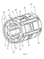
- FIG. 1 shows as an embodiment of the invention in a perspective view elements 10, 20 and 30 of a linear ball bearing with a plurality, provided for endless circulation ball rows.
- a linear ball bearing with a plurality, provided for endless circulation ball rows.
- Through the hollow of the in the FIG. 1 illustrated linear ball bearing is an axis or shaft provided for passing, so that via the load-bearing balls and raceway inserts 60, the linear ball bearing with respect to the axis or shaft is at least longitudinally displaceable.
- the balls as well as the axis or shaft are not shown.
- the linear ball bearing comprises a hollow cylinder-like base member 10 with substantially rectilinear guides 14 for the loaded and unloaded balls and receiving openings for track inserts 60, so that the loaded balls roll on the one hand on the axle or shaft and on the other hand on the raceway inserts 60.
- the raceway inserts 60 are formed outwardly according to a longitudinal strip of a cylinder jacket, in other embodiments, also raceway elements can be used, the outer, central region has a radially outward bulge, which then with the linear ball bearing misalignment up to a certain Degree can be compensated.
- one and the same elements 10, 20 and 30 can be used both for the angle-adjustable and for a comparable, non-angle-adjustable design.
- both axial ends of the base member 10 is formed similar.
- said axial end of the base member 10 is formed in the region of the outer shell of the base member 10 with such an axial projection 11 that in the cavity of the projection 11, a deflecting element 20 and a cover member 30 are snapped.
- the deflecting element 20 is shown in the snapped-in state.
- the FIG. 2 also shows a perspective view of the deflecting element 20 in isolation.
- the deflecting element 20 comprises semicircular guides 24 by means of which the balls are deflected between the rectilinear guides 14 in the base element 10 for the loaded and unloaded balls.
- the projection 11 is formed for said snapping with the projection 11 radially penetrating openings 12, in which corresponding radial projections 22 of the deflecting element 20 are provided for snapping.
- the openings 12 and the extensions 22 are arranged and adapted to one another such that the base element 10 and the deflecting element 20 can be connected to one another only in a predefinable rotational position, so that the guides 24 in the deflection element 20 fit precisely to that of the base element 10.
- the deflecting element 20 is formed on the outwardly directed end side in an inner edge region with sector-like axial projections 26, so that between the sector-like extensions 26 and this simultaneously enclosing, a ring-like lubricant reservoir 40 can be used.
- a ring-like lubricant reservoir 40 can be used between the sector-like extensions 26 of the deflecting element 20, the lubricant reservoir 40 between the sector-like projections 26 radially inwardly toward the axis or shaft projecting projections 46 which serve to lubricate the axle or shaft exclusively in those areas where the balls for Rolling are provided.
- the sector-like extensions 26 are also placed on the deflection element 20 in such a way that the extensions 46 of the lubricant reservoir 40 projecting radially inwards satisfy the aforementioned condition. Furthermore, the sector-like extensions 26 on the deflecting element 20 and the radial extensions 46 on the lubricant reservoir 40 are arranged and adapted to one another in such a way that a relative to the mutual rotational position correct assembly is enforced, so to speak.
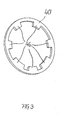
- the lubricant reservoir 40 is shown inserted into the deflecting element 20 state, whereas he in FIG. 3 again shown in isolation in perspective.
- the lubricant reservoir 40 from a porous material, such as foam, be formed and serve as an oil lubricant, with which the foam is impregnated. Due to the fact that only areas are lubricated, on which the balls roll on the axis or shaft, the service life of the once filled with lubricant lubricant reservoir 40 is increased significantly, up to a lifetime lubrication. In other embodiments, however, an embodiment in which oil is held in a polymeric matrix, which is also known under the keyword "solid oil", used and / or relubricated.
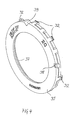
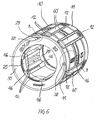
- FIG. 1 shown linear ball bearings finally by the fact that from the left side still in the FIG. 4 shown cover member 30 is snapped into the projection 11 of the base member 10 so that the linear ball bearing accordingly FIG. 6 results.
- the cover member 30 is snapped into the same openings 12 of the projection 11, including the cover member 30 has correspondingly formed radial extensions 32.
- the radial extensions 32 on the cover element 30 and the openings 12 of the projection 11 are arranged and adapted to one another in such a way that with respect to the mutual rotational position correct assembly is enforced so to speak.
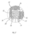
- a seal 50 are arranged, which serves to seal the linear ball bearing relative to the axis or shaft. It shows the FIG. 5 a section of a longitudinal section of the arranged between the deflecting element 20 and the cover member 30 seal 50.
- the seal 50 is formed as a self-contained ring.
- the seal 50 is of uniform material and made in one piece from an elastomeric material.
- the longitudinal section of the seal 50 in this case has a rectangular base region 52, at which radially outwardly an annular circumferential bead 54 connects and connect to the inner shell an obliquely outwardly and an obliquely inwardly projecting sealing lip 56 and 57.
- the sector-like axial extensions 26 of the deflecting element 20 are provided with axially projecting lugs 27, which are provided for engagement between said rectangular base portion 52 and the obliquely inwardly facing sealing lip 57.
- the cover element 30 is on the inner shell side formed with an annular circumferential, axially inwardly projecting nose 37, which is provided for engagement between the rectangular base portion 52 of the seal 50 and the obliquely outwardly projecting sealing lip 56 of the seal 50 for engagement.
- the base member 10 of the linear ball bearing is further formed in a central region with a recess 16 which serves to secure against axial and rotation secured against an installation environment and can also be used as a grease nipple for relubrication of the linear ball bearing.
- this peripheral point for the torsion-proof fastening is characterized on the face side both on the end face of the projection 11 of the base element 10 and on the cover element 30 by corresponding markings 18 and 38, which considerably simplifies the angular position-correct mounting of the linear ball bearing.
- the linear ball bearing is designed for a predefinable, at a certain circumferential point substantially perpendicular to the cylinder jacket main load direction, which is also marked on the front side of the linear ball bearing by a marker.
- the marking is realized by an axially projecting projection 29 on the deflecting element 20, which engages in a corresponding recess 39 of the cover member 30.
- the cover element 30 and the deflecting element 20 are formed differently colored, so that the marking is particularly recognizable. This marking also facilitates the proper installation of the linear ball bearing with respect to the main load direction.
- the FIGS. 7 and 8 show again in the FIG. 6 With A and B designated detail enlargements of the front page in the area of the markers 18 and 38th
- the elements 10, 20 and 30 are in particular produced by injection molding from a plastic.
- the deflecting element 20 and the cover element 30 are formed in the axial direction free of undercuts, which makes their injection-molding production particularly simple and therefore cost-effective. Elaborate slides on the injection molding tool are therefore not required with advantage.
- the basic element is designed in this respect with particular advantage such that it is exclusively axially demoldable inside and only radially outwardly must be removed from the mold. This can also be a simple design injection molding tool used, which in turn has a positive effect on the cost position. Particularly noteworthy is that the production with special advantage without a forced removal manages.
- FIG. 9 shows as a further embodiment of the invention in a perspective view a linear ball bearing, which unlike the linear ball bearing of FIGS. 1 to 8 in the circumferential direction is not formed in a hollow cylinder-like closed, but the hollow cylinder is formed in a sector-like peripheral portion with an opening which detects the full wall thickness and the entire longitudinal extent of the linear ball bearing.
- the linear ball bearing of FIG. 9 is similar to the linear ball bearing FIGS. 1 to 8 composed of the there designated elements 10 ', 20' and 30 '.
- a seal 50 'be inserted, extending from the seal 50 according to the FIG. 5 differs in that the seal 50 'forms no self-contained ring and that also on the outer shell side instead of the annular circumferential bead 54, an obliquely outwardly projecting extension 54' is formed, which is corresponding in the FIGS. 10 to 12 is shown.
- the FIG. 10 shows a front view, the FIG. 11 a longitudinal section along the line CC of FIG. 10 and the FIG. 12 that in the FIG. 10 D detail of the seal 50 '.
- the seal design according to the FIGS. 10 to 12 be applied in a circumferentially closed self-contained, hollow cylinder-like linear bearings and vice versa, of course, a corresponding to the FIG. 5 formed seal at a circumferentially not closed in itself formed linear roller bearings are used.
Landscapes
- Engineering & Computer Science (AREA)
- General Engineering & Computer Science (AREA)
- Mechanical Engineering (AREA)
- Bearings For Parts Moving Linearly (AREA)
- Rolling Contact Bearings (AREA)
Applications Claiming Priority (1)
| Application Number | Priority Date | Filing Date | Title |
|---|---|---|---|
| DE102007012650.8A DE102007012650B4 (de) | 2007-03-16 | 2007-03-16 | Linearwälzlager |
Publications (3)
| Publication Number | Publication Date |
|---|---|
| EP1970581A2 true EP1970581A2 (fr) | 2008-09-17 |
| EP1970581A3 EP1970581A3 (fr) | 2012-04-25 |
| EP1970581B1 EP1970581B1 (fr) | 2013-01-02 |
Family
ID=39587953
Family Applications (1)
| Application Number | Title | Priority Date | Filing Date |
|---|---|---|---|
| EP20080004584 Active EP1970581B1 (fr) | 2007-03-16 | 2008-03-12 | Palier à roulement linéaire |
Country Status (2)
| Country | Link |
|---|---|
| EP (1) | EP1970581B1 (fr) |
| DE (1) | DE102007012650B4 (fr) |
Cited By (1)
| Publication number | Priority date | Publication date | Assignee | Title |
|---|---|---|---|---|
| JP2012163184A (ja) * | 2011-02-09 | 2012-08-30 | Nippon Thompson Co Ltd | 潤滑機能を備えた極小形の直動案内ユニット |
Families Citing this family (1)
| Publication number | Priority date | Publication date | Assignee | Title |
|---|---|---|---|---|
| DE202009014395U1 (de) * | 2009-10-24 | 2011-03-10 | Robert Bosch Gmbh | Linearführungsvorrichtung mit geschützter Dichtlippe |
Citations (1)
| Publication number | Priority date | Publication date | Assignee | Title |
|---|---|---|---|---|
| DE4015124A1 (de) | 1990-05-11 | 1991-11-14 | Skf Linearsysteme Gmbh | Kugellager fuer laengsbewegungen |
Family Cites Families (6)
| Publication number | Priority date | Publication date | Assignee | Title |
|---|---|---|---|---|
| JPS62237113A (ja) * | 1986-04-05 | 1987-10-17 | Nippon Thompson Co Ltd | ボ−ルスプライン軸受 |
| JP2981730B2 (ja) * | 1997-04-23 | 1999-11-22 | 日本ベアリング株式会社 | 軸受部材 |
| US6401867B1 (en) * | 1998-04-16 | 2002-06-11 | Thk Co., Ltd. | Lubricant supply system |
| JP4199850B2 (ja) * | 1998-07-14 | 2008-12-24 | 日本トムソン株式会社 | 潤滑プレートを備えた直動案内ユニット |
| JP2000035038A (ja) * | 1998-07-16 | 2000-02-02 | Nippon Thompson Co Ltd | 潤滑プレートを備えた直動案内ユニット |
| US20060102427A1 (en) * | 2004-11-12 | 2006-05-18 | Ching-Shan Wu | Lubricant supply unit |
-
2007
- 2007-03-16 DE DE102007012650.8A patent/DE102007012650B4/de not_active Expired - Fee Related
-
2008
- 2008-03-12 EP EP20080004584 patent/EP1970581B1/fr active Active
Patent Citations (1)
| Publication number | Priority date | Publication date | Assignee | Title |
|---|---|---|---|---|
| DE4015124A1 (de) | 1990-05-11 | 1991-11-14 | Skf Linearsysteme Gmbh | Kugellager fuer laengsbewegungen |
Cited By (1)
| Publication number | Priority date | Publication date | Assignee | Title |
|---|---|---|---|---|
| JP2012163184A (ja) * | 2011-02-09 | 2012-08-30 | Nippon Thompson Co Ltd | 潤滑機能を備えた極小形の直動案内ユニット |
Also Published As
| Publication number | Publication date |
|---|---|
| EP1970581A3 (fr) | 2012-04-25 |
| DE102007012650A1 (de) | 2008-09-25 |
| EP1970581B1 (fr) | 2013-01-02 |
| DE102007012650B4 (de) | 2017-11-02 |
Similar Documents
| Publication | Publication Date | Title |
|---|---|---|
| DE10353098B4 (de) | Aus einem Harz hergestellter Kugelhalter für ein Kugellager | |
| DE112010002176T5 (de) | Bewegungs-Führungsvorrichtung und Spindelvorrichtung | |
| DE102011117820A1 (de) | Dichtring mit Führungselement | |
| DE102014210171A1 (de) | Führungswagen mit Befestigungsbohrung, welche Bestandteil eines Schmiermittelströmungspfades ist | |
| DE69923037T2 (de) | Linearführungseinheit mit einer Schmierungsscheibe | |
| DE102016113220A1 (de) | Kugellager | |
| DE2156081A1 (de) | Wälzlager | |
| EP2475903B1 (fr) | Dispositif de génération de pression de charge | |
| DE102016213359A1 (de) | Lageranordnung | |
| DE112021005705T5 (de) | Wälzlager | |
| DE2711882A1 (de) | Kugelbuechse | |
| EP1970582B1 (fr) | Joint dans un roulement linéaire | |
| DE9003461U1 (de) | Wälzlager mit eingeschnapptem Käfig | |
| DE102015220151B4 (de) | Lageranordnung und Dichtung | |
| EP1970581B1 (fr) | Palier à roulement linéaire | |
| DE3009977A1 (de) | Dichtungsvorrichtung fuer ein waelzlager | |
| EP1970583B1 (fr) | Palier à roulement linéaire | |
| DE112019004538T5 (de) | Fahrzeugradlagervorrichtung | |
| DE602004006557T2 (de) | Kreuzgelenk mit einer Vorrichtung zum Abdichten der Lagerbüchse des Kreuzgelenkes | |
| EP1970584B1 (fr) | Palier à roulement linéaire | |
| DE102010014742A1 (de) | Faltenbalglager | |
| DE2824687A1 (de) | Sicherungsring fuer waelzlager | |
| DE112008000851T5 (de) | Dichtteil für eine Wälzvorrichtung und Wälzvorrichtung | |
| DE102011010231A1 (de) | Gewindetrieb mit Schmiereinrichtung umfassend einen elastischen Schmiernippel | |
| DE4322761A1 (de) | Wälzlager |
Legal Events
| Date | Code | Title | Description |
|---|---|---|---|
| PUAI | Public reference made under article 153(3) epc to a published international application that has entered the european phase |
Free format text: ORIGINAL CODE: 0009012 |
|
| AK | Designated contracting states |
Kind code of ref document: A2 Designated state(s): AT BE BG CH CY CZ DE DK EE ES FI FR GB GR HR HU IE IS IT LI LT LU LV MC MT NL NO PL PT RO SE SI SK TR |
|
| AX | Request for extension of the european patent |
Extension state: AL BA MK RS |
|
| PUAL | Search report despatched |
Free format text: ORIGINAL CODE: 0009013 |
|
| AK | Designated contracting states |
Kind code of ref document: A3 Designated state(s): AT BE BG CH CY CZ DE DK EE ES FI FR GB GR HR HU IE IS IT LI LT LU LV MC MT NL NO PL PT RO SE SI SK TR |
|
| AX | Request for extension of the european patent |
Extension state: AL BA MK RS |
|
| RIC1 | Information provided on ipc code assigned before grant |
Ipc: F16C 33/66 20060101ALI20120316BHEP Ipc: F16C 29/06 20060101AFI20120316BHEP |
|
| 17P | Request for examination filed |
Effective date: 20120702 |
|
| GRAP | Despatch of communication of intention to grant a patent |
Free format text: ORIGINAL CODE: EPIDOSNIGR1 |
|
| GRAS | Grant fee paid |
Free format text: ORIGINAL CODE: EPIDOSNIGR3 |
|
| GRAA | (expected) grant |
Free format text: ORIGINAL CODE: 0009210 |
|
| AK | Designated contracting states |
Kind code of ref document: B1 Designated state(s): AT BE BG CH CY CZ DE DK EE ES FI FR GB GR HR HU IE IS IT LI LT LU LV MC MT NL NO PL PT RO SE SI SK TR |
|
| AKX | Designation fees paid |
Designated state(s): AT BE BG CH CY CZ DE DK EE ES FI FR GB GR HR HU IE IS IT LI LT LU LV MC MT NL NO PL PT RO SE SI SK TR |
|
| REG | Reference to a national code |
Ref country code: GB Ref legal event code: FG4D Free format text: NOT ENGLISH |
|
| REG | Reference to a national code |
Ref country code: CH Ref legal event code: EP Ref country code: AT Ref legal event code: REF Ref document number: 591782 Country of ref document: AT Kind code of ref document: T Effective date: 20130115 |
|
| REG | Reference to a national code |
Ref country code: IE Ref legal event code: FG4D Free format text: LANGUAGE OF EP DOCUMENT: GERMAN |
|
| REG | Reference to a national code |
Ref country code: DE Ref legal event code: R096 Ref document number: 502008008980 Country of ref document: DE Effective date: 20130228 |
|
| REG | Reference to a national code |
Ref country code: NL Ref legal event code: VDEP Effective date: 20130102 |
|
| PG25 | Lapsed in a contracting state [announced via postgrant information from national office to epo] |
Ref country code: SI Free format text: LAPSE BECAUSE OF FAILURE TO SUBMIT A TRANSLATION OF THE DESCRIPTION OR TO PAY THE FEE WITHIN THE PRESCRIBED TIME-LIMIT Effective date: 20130102 |
|
| REG | Reference to a national code |
Ref country code: LT Ref legal event code: MG4D |
|
| PG25 | Lapsed in a contracting state [announced via postgrant information from national office to epo] |
Ref country code: LT Free format text: LAPSE BECAUSE OF FAILURE TO SUBMIT A TRANSLATION OF THE DESCRIPTION OR TO PAY THE FEE WITHIN THE PRESCRIBED TIME-LIMIT Effective date: 20130102 Ref country code: CZ Free format text: LAPSE BECAUSE OF FAILURE TO SUBMIT A TRANSLATION OF THE DESCRIPTION OR TO PAY THE FEE WITHIN THE PRESCRIBED TIME-LIMIT Effective date: 20130102 Ref country code: ES Free format text: LAPSE BECAUSE OF FAILURE TO SUBMIT A TRANSLATION OF THE DESCRIPTION OR TO PAY THE FEE WITHIN THE PRESCRIBED TIME-LIMIT Effective date: 20130413 Ref country code: SE Free format text: LAPSE BECAUSE OF FAILURE TO SUBMIT A TRANSLATION OF THE DESCRIPTION OR TO PAY THE FEE WITHIN THE PRESCRIBED TIME-LIMIT Effective date: 20130102 Ref country code: BG Free format text: LAPSE BECAUSE OF FAILURE TO SUBMIT A TRANSLATION OF THE DESCRIPTION OR TO PAY THE FEE WITHIN THE PRESCRIBED TIME-LIMIT Effective date: 20130402 Ref country code: IS Free format text: LAPSE BECAUSE OF FAILURE TO SUBMIT A TRANSLATION OF THE DESCRIPTION OR TO PAY THE FEE WITHIN THE PRESCRIBED TIME-LIMIT Effective date: 20130502 Ref country code: NO Free format text: LAPSE BECAUSE OF FAILURE TO SUBMIT A TRANSLATION OF THE DESCRIPTION OR TO PAY THE FEE WITHIN THE PRESCRIBED TIME-LIMIT Effective date: 20130402 |
|
| PG25 | Lapsed in a contracting state [announced via postgrant information from national office to epo] |
Ref country code: LV Free format text: LAPSE BECAUSE OF FAILURE TO SUBMIT A TRANSLATION OF THE DESCRIPTION OR TO PAY THE FEE WITHIN THE PRESCRIBED TIME-LIMIT Effective date: 20130102 Ref country code: GR Free format text: LAPSE BECAUSE OF FAILURE TO SUBMIT A TRANSLATION OF THE DESCRIPTION OR TO PAY THE FEE WITHIN THE PRESCRIBED TIME-LIMIT Effective date: 20130403 Ref country code: FI Free format text: LAPSE BECAUSE OF FAILURE TO SUBMIT A TRANSLATION OF THE DESCRIPTION OR TO PAY THE FEE WITHIN THE PRESCRIBED TIME-LIMIT Effective date: 20130102 Ref country code: PT Free format text: LAPSE BECAUSE OF FAILURE TO SUBMIT A TRANSLATION OF THE DESCRIPTION OR TO PAY THE FEE WITHIN THE PRESCRIBED TIME-LIMIT Effective date: 20130502 Ref country code: NL Free format text: LAPSE BECAUSE OF FAILURE TO SUBMIT A TRANSLATION OF THE DESCRIPTION OR TO PAY THE FEE WITHIN THE PRESCRIBED TIME-LIMIT Effective date: 20130102 Ref country code: PL Free format text: LAPSE BECAUSE OF FAILURE TO SUBMIT A TRANSLATION OF THE DESCRIPTION OR TO PAY THE FEE WITHIN THE PRESCRIBED TIME-LIMIT Effective date: 20130102 |
|
| BERE | Be: lapsed |
Owner name: A.B. SKF Effective date: 20130331 |
|
| PG25 | Lapsed in a contracting state [announced via postgrant information from national office to epo] |
Ref country code: HR Free format text: LAPSE BECAUSE OF FAILURE TO SUBMIT A TRANSLATION OF THE DESCRIPTION OR TO PAY THE FEE WITHIN THE PRESCRIBED TIME-LIMIT Effective date: 20130102 |
|
| PG25 | Lapsed in a contracting state [announced via postgrant information from national office to epo] |
Ref country code: MC Free format text: LAPSE BECAUSE OF NON-PAYMENT OF DUE FEES Effective date: 20130331 Ref country code: EE Free format text: LAPSE BECAUSE OF FAILURE TO SUBMIT A TRANSLATION OF THE DESCRIPTION OR TO PAY THE FEE WITHIN THE PRESCRIBED TIME-LIMIT Effective date: 20130102 Ref country code: SK Free format text: LAPSE BECAUSE OF FAILURE TO SUBMIT A TRANSLATION OF THE DESCRIPTION OR TO PAY THE FEE WITHIN THE PRESCRIBED TIME-LIMIT Effective date: 20130102 Ref country code: RO Free format text: LAPSE BECAUSE OF FAILURE TO SUBMIT A TRANSLATION OF THE DESCRIPTION OR TO PAY THE FEE WITHIN THE PRESCRIBED TIME-LIMIT Effective date: 20130102 Ref country code: DK Free format text: LAPSE BECAUSE OF FAILURE TO SUBMIT A TRANSLATION OF THE DESCRIPTION OR TO PAY THE FEE WITHIN THE PRESCRIBED TIME-LIMIT Effective date: 20130102 |
|
| PLBE | No opposition filed within time limit |
Free format text: ORIGINAL CODE: 0009261 |
|
| STAA | Information on the status of an ep patent application or granted ep patent |
Free format text: STATUS: NO OPPOSITION FILED WITHIN TIME LIMIT |
|
| PG25 | Lapsed in a contracting state [announced via postgrant information from national office to epo] |
Ref country code: CY Free format text: LAPSE BECAUSE OF FAILURE TO SUBMIT A TRANSLATION OF THE DESCRIPTION OR TO PAY THE FEE WITHIN THE PRESCRIBED TIME-LIMIT Effective date: 20130102 |
|
| 26N | No opposition filed |
Effective date: 20131003 |
|
| PG25 | Lapsed in a contracting state [announced via postgrant information from national office to epo] |
Ref country code: IT Free format text: LAPSE BECAUSE OF FAILURE TO SUBMIT A TRANSLATION OF THE DESCRIPTION OR TO PAY THE FEE WITHIN THE PRESCRIBED TIME-LIMIT Effective date: 20130102 |
|
| REG | Reference to a national code |
Ref country code: IE Ref legal event code: MM4A |
|
| REG | Reference to a national code |
Ref country code: DE Ref legal event code: R097 Ref document number: 502008008980 Country of ref document: DE Effective date: 20131003 |
|
| PG25 | Lapsed in a contracting state [announced via postgrant information from national office to epo] |
Ref country code: BE Free format text: LAPSE BECAUSE OF NON-PAYMENT OF DUE FEES Effective date: 20130331 Ref country code: IE Free format text: LAPSE BECAUSE OF NON-PAYMENT OF DUE FEES Effective date: 20130312 |
|
| REG | Reference to a national code |
Ref country code: AT Ref legal event code: MM01 Ref document number: 591782 Country of ref document: AT Kind code of ref document: T Effective date: 20130312 |
|
| PG25 | Lapsed in a contracting state [announced via postgrant information from national office to epo] |
Ref country code: MT Free format text: LAPSE BECAUSE OF FAILURE TO SUBMIT A TRANSLATION OF THE DESCRIPTION OR TO PAY THE FEE WITHIN THE PRESCRIBED TIME-LIMIT Effective date: 20130102 |
|
| PG25 | Lapsed in a contracting state [announced via postgrant information from national office to epo] |
Ref country code: AT Free format text: LAPSE BECAUSE OF NON-PAYMENT OF DUE FEES Effective date: 20130312 |
|
| PG25 | Lapsed in a contracting state [announced via postgrant information from national office to epo] |
Ref country code: TR Free format text: LAPSE BECAUSE OF FAILURE TO SUBMIT A TRANSLATION OF THE DESCRIPTION OR TO PAY THE FEE WITHIN THE PRESCRIBED TIME-LIMIT Effective date: 20130102 |
|
| PG25 | Lapsed in a contracting state [announced via postgrant information from national office to epo] |
Ref country code: HU Free format text: LAPSE BECAUSE OF FAILURE TO SUBMIT A TRANSLATION OF THE DESCRIPTION OR TO PAY THE FEE WITHIN THE PRESCRIBED TIME-LIMIT; INVALID AB INITIO Effective date: 20080312 Ref country code: LU Free format text: LAPSE BECAUSE OF NON-PAYMENT OF DUE FEES Effective date: 20130312 |
|
| REG | Reference to a national code |
Ref country code: FR Ref legal event code: PLFP Year of fee payment: 9 |
|
| REG | Reference to a national code |
Ref country code: FR Ref legal event code: PLFP Year of fee payment: 10 |
|
| REG | Reference to a national code |
Ref country code: FR Ref legal event code: PLFP Year of fee payment: 11 |
|
| REG | Reference to a national code |
Ref country code: DE Ref legal event code: R082 Ref document number: 502008008980 Country of ref document: DE Representative=s name: HEYERHOFF GEIGER GMBH & CO. KG, DE Ref country code: DE Ref legal event code: R082 Ref document number: 502008008980 Country of ref document: DE Representative=s name: HEYERHOFF GEIGER & PARTNER PATENTANWAELTE PART, DE |
|
| REG | Reference to a national code |
Ref country code: DE Ref legal event code: R081 Ref document number: 502008008980 Country of ref document: DE Owner name: SCHAEFFLER TECHNOLOGIES AG & CO. KG, DE Free format text: FORMER OWNER: AB SKF, GOETEBORG, SE Ref country code: DE Ref legal event code: R082 Ref document number: 502008008980 Country of ref document: DE Representative=s name: HEYERHOFF GEIGER & PARTNER PATENTANWAELTE PART, DE Ref country code: DE Ref legal event code: R081 Ref document number: 502008008980 Country of ref document: DE Owner name: EWELLIX AB, SE Free format text: FORMER OWNER: AB SKF, GOETEBORG, SE |
|
| PGFP | Annual fee paid to national office [announced via postgrant information from national office to epo] |
Ref country code: GB Payment date: 20200325 Year of fee payment: 13 |
|
| PGFP | Annual fee paid to national office [announced via postgrant information from national office to epo] |
Ref country code: CH Payment date: 20200325 Year of fee payment: 13 |
|
| REG | Reference to a national code |
Ref country code: CH Ref legal event code: PL |
|
| GBPC | Gb: european patent ceased through non-payment of renewal fee |
Effective date: 20210312 |
|
| PG25 | Lapsed in a contracting state [announced via postgrant information from national office to epo] |
Ref country code: LI Free format text: LAPSE BECAUSE OF NON-PAYMENT OF DUE FEES Effective date: 20210331 Ref country code: CH Free format text: LAPSE BECAUSE OF NON-PAYMENT OF DUE FEES Effective date: 20210331 Ref country code: GB Free format text: LAPSE BECAUSE OF NON-PAYMENT OF DUE FEES Effective date: 20210312 |
|
| P01 | Opt-out of the competence of the unified patent court (upc) registered |
Effective date: 20230514 |
|
| REG | Reference to a national code |
Ref country code: DE Ref legal event code: R081 Ref document number: 502008008980 Country of ref document: DE Owner name: SCHAEFFLER TECHNOLOGIES AG & CO. KG, DE Free format text: FORMER OWNER: EWELLIX AB, GOETEBORG, SE Ref country code: DE Ref legal event code: R082 Ref document number: 502008008980 Country of ref document: DE Ref country code: DE Ref legal event code: R082 Ref document number: 502008008980 Country of ref document: DE Representative=s name: HEYERHOFF GEIGER GMBH & CO. KG, DE |
|
| REG | Reference to a national code |
Ref country code: DE Ref legal event code: R082 Ref document number: 502008008980 Country of ref document: DE Representative=s name: HEYERHOFF GEIGER GMBH & CO. KG, DE |
|
| PGFP | Annual fee paid to national office [announced via postgrant information from national office to epo] |
Ref country code: DE Payment date: 20260331 Year of fee payment: 19 |
|
| REG | Reference to a national code |
Ref country code: DE Ref legal event code: R082 Ref document number: 502008008980 Country of ref document: DE |
|
| PGFP | Annual fee paid to national office [announced via postgrant information from national office to epo] |
Ref country code: FR Payment date: 20260320 Year of fee payment: 19 |